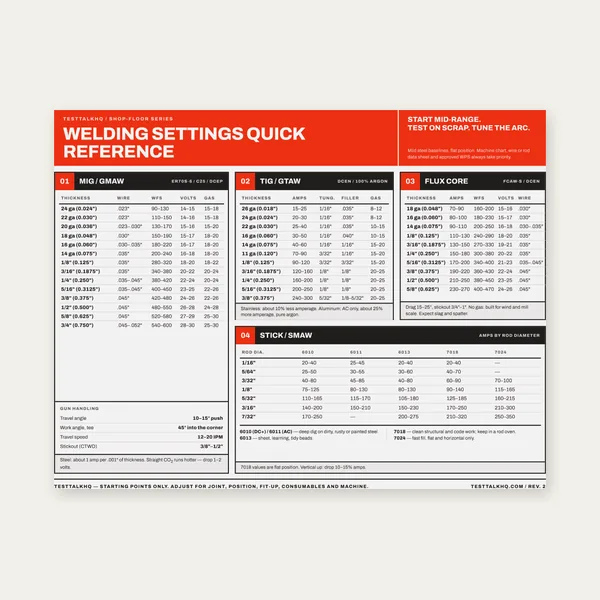
Welding Reference Card
One page. MIG, TIG, stick and flux core settings by thickness.
$3.99
BuyCalculate correct wire size and breaker rating for your welder — NEC-oriented sizing
Size dedicated welder branch circuits with confidence: input voltage, nameplate input amperage, one-way run length, and conductor material feed the same logic as the live calculator (125% adjusted load, ampacity tables, voltage-drop bump, standard breaker ladder, and NEMA receptacle hints).
One page. MIG, TIG, stick and flux core settings by thickness.
$3.99
Buy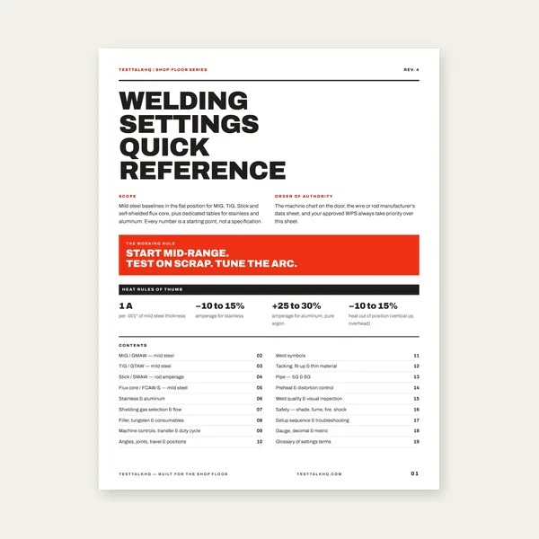
19 pages. Four processes, stainless and aluminum, symbols and inspection.
$12.99
Buy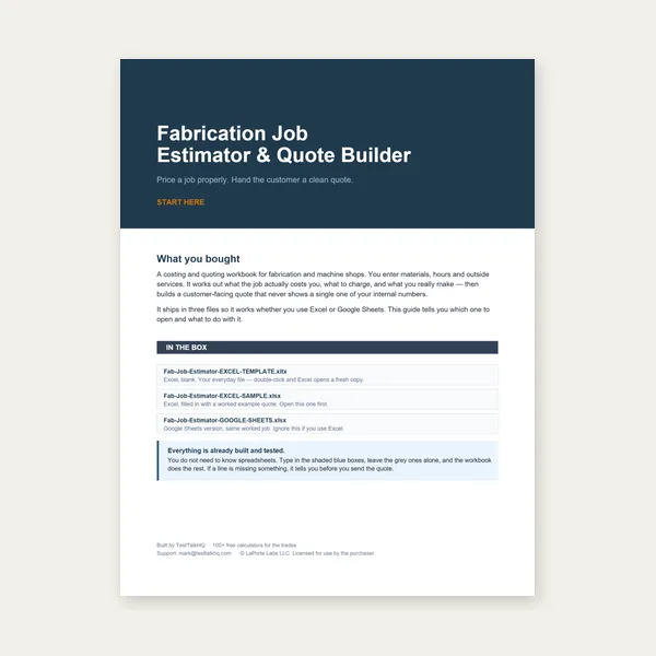
Price the job, then hand over a quote with no internal numbers.
Excel or Google Sheets. Best on a computer.
$29.00
Buy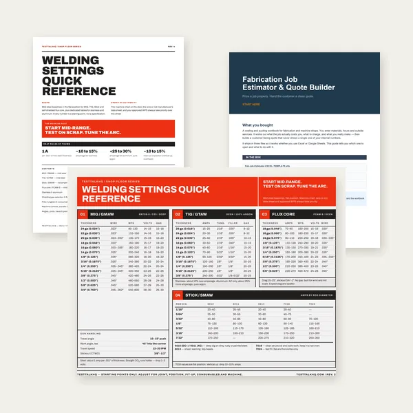
Card, 19-page guide and the estimator workbook. All six files.
Excel or Google Sheets. Best on a computer.
$34.99
$45.98 if bought separately — save $10.99
BuyCheckout opens in a new tab.
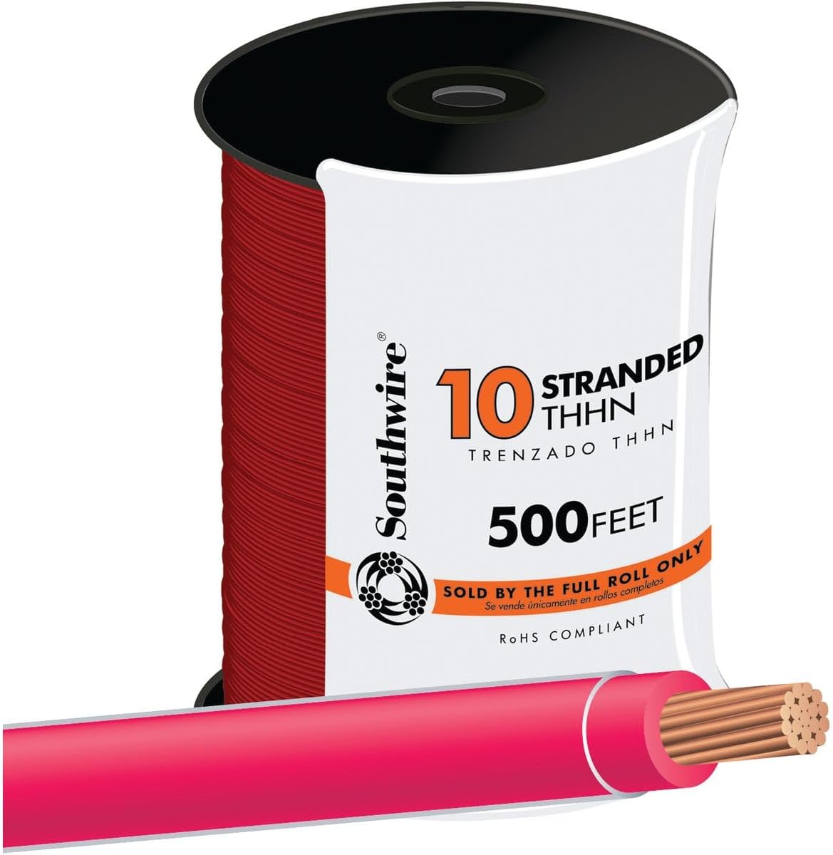
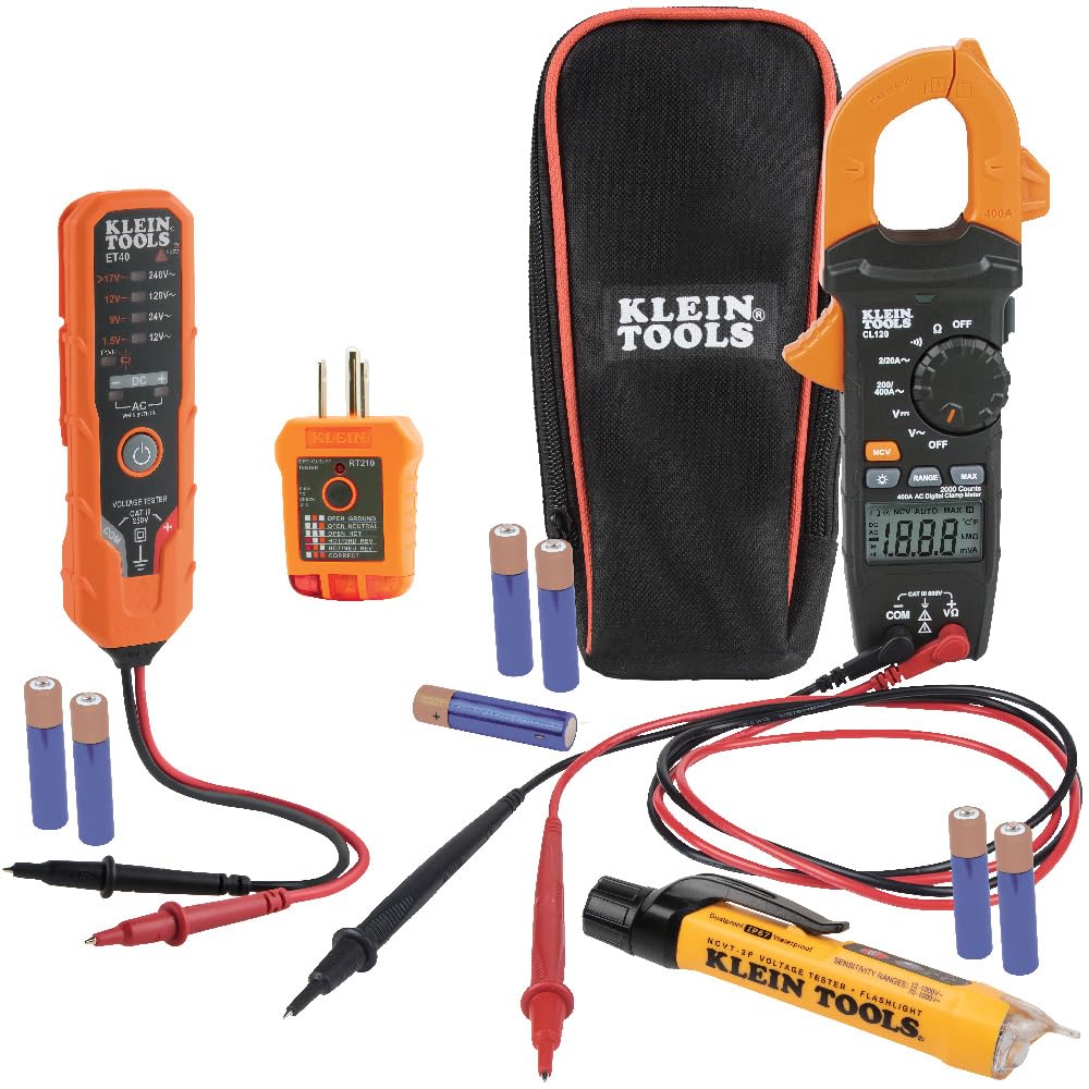
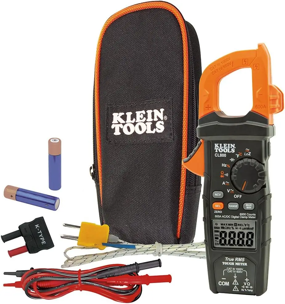
Cu conductors, safe terminations, and meters to validate your install after sizing a welder circuit.

As an Amazon Associate, TestTalkHQ earns from qualifying purchases.
Welding machines draw significant amperage, especially during arc startup. Using undersized wire creates dangerous conditions: overheating, voltage sag that affects weld quality, nuisance breaker trips, and potential fire hazards. The National Electrical Code (NEC) provides specific guidance for welder circuits under Article 630 because welders operate differently than continuous-duty appliances.
Unlike your refrigerator or air conditioner that run at steady amperage, welders pull heavy current in bursts. A 180-amp MIG welder might draw 30 amps from your wall during welding, but only during the time you're actually welding. This is the duty cycle, typically 20–40% for hobbyist machines. The NEC allows you to use smaller wire and breakers for welders than you'd need for a continuous 30-amp load, but only if you follow specific calculations and labeling requirements.
This is where most people get twisted up. Your welder has two current ratings that mean completely different things.
Output Current (Welding Amps):
This is the amperage at the welding electrode. A 180-amp MIG welder puts out 180 amps maximum at the torch.
Input Current (Primary Amps):
This is what the welder draws from your electrical panel. This is what matters for wire sizing. A 180-amp output welder typically draws 25–35 amps input at 240V depending on efficiency and settings.
Do not assume. A Lincoln Electric 180 and a Hobart 180 might have different input currents even though they are both 180-amp welders.
The NEC recognizes that welders do not run continuously, so it allows special sizing under Article 630.
Duty Cycle Allowance: NEC allows you to size conductors and overcurrent protection based on the welder's duty cycle.
Standard calculation:
For many installs, people simplify to Input Current × 1.25 for a safe branch-circuit sizing baseline.
Oversized breaker allowance: Unlike normal circuits where the breaker must match wire size, welder circuits can have larger breakers than the wire would normally allow if the welder's duty cycle justifies it.
Required marking: NEC 630.13 requires the receptacle be labeled For Welder Use Only if you use smaller wire than standard ampacity tables allow.
Dedicated circuit requirement: NEC 630.11 requires dedicated branch circuits for arc welders.
| Wire Size | Ampacity | Typical Welder Application |
|---|---|---|
| 14 AWG | 20A | Small 120V 100–120A welders |
| 12 AWG | 25A | 120V 140A welders |
| 10 AWG | 35A | 240V 140–180A welders |
| 8 AWG | 50A | 240V 180–210A welders |
| 6 AWG | 65A | 240V 210–250A welders |
| 4 AWG | 85A | 240V 250–300A welders |
| 3 AWG | 100A | Heavy 300A+ industrial welders |
| 2 AWG | 115A | Industrial/commercial welders |
Note: These ampacities assume 75°C rated wire (THHN/THWN) in conduit with normal ambient temperature and no more than three current-carrying conductors.
Aluminum wire ampacity is roughly 60–65% of copper. It can work, but it is less forgiving and not the move for most DIY installs.
Voltage drop is the voltage lost in the wire between your panel and the welder. Too much drop and your welder cannot maintain arc properly.
Voltage drop formula:
VD = (2 × K × I × D) / CM
Real-world example:
30A welder, 100 feet away, 10 AWG copper gives about 3.1% drop on 240V. That is barely acceptable. 8 AWG is better.
The receptacle has to match both the voltage and amperage of your circuit.
Mistake #1: Using Output Amps Instead of Input Amps
Use nameplate input amperage, not the amperage at the stinger or gun.
Mistake #2: Sharing Circuits
Welder circuits should be dedicated.
Mistake #3: Undersizing for Future Upgrades
If you know a bigger machine is probably coming, run bigger wire now.
Mistake #4: Ignoring Voltage Drop
Long runs punish undersized wire. Shop feeds and outbuildings: voltage drop long runs.
Mistake #5: Wrong Receptacle Type
Adapters are where a lot of dumb decisions start.
Mistake #6: Aluminum Wire Without Proper Training
It requires different handling, anti-oxidant compound, and correct termination torque.
Mistake #7: Overloading Panel Capacity
Empty breaker spaces do not automatically mean the panel has room for the load.
Many welders offer dual voltage. If you are currently running 120V but want better performance, 240V gives you more output capability, lower current draw for the same power, less voltage drop, and usually a happier machine overall.
What's required: 240V circuit, double-pole breaker, correct receptacle, and a welder that supports 240V input.
Cost comparison:
Installing a 240V circuit is often cheaper than replacing a decent dual-voltage welder with a bigger 120V-only machine.
Before adding a welder circuit, verify your electrical panel has capacity.
Example:
200A service panel, existing load 120A average, adding a 50A welder circuit puts you around 170A. That is usually fine with some headroom.
If your panel is close to the limit, you may need a service upgrade, subpanel, or better load management.
Size flexible welding cable (stinger/work leads) separately from branch-circuit wire above — see the Welding Cable Size Guide. This page sizes building wire to the outlet — not MIG filler wire or stinger cable.
Article 2 is already covered: branch-circuit ampacity, hot conductors, wrong temperature columns, and missed derating belong in Wire Ampacity Troubleshooting. Input extension-cord sag belongs in Extension Cord Voltage Drop Troubleshooting. Soft arc, hot lugs, and output-lead faults belong in Welding Cable Size Troubleshooting. Fixed building-wire sag that is not cord or welding-cable specific: voltage drop troubleshooting.
Article 3 is already covered: the Welding Cable Size Guide separates branch-circuit building wire, flexible welding leads, and MIG/TIG filler. MIG diameter choices are handled by the MIG Wire Diameter Guide.
The chart already exists: the canonical Welding Wire Gauge Chart expands the guide material into five quick-reference tables with full standalone prose. The legacy chart-guide slug redirects there, so no additional chart is needed.
Before you pull cable through conduit, estimate tension and sidewall pressure with the Wire Pulling Tension Calculator. Formulas and jam-ratio checks are in the Wire Pulling Tension Guide. If a pull sticks or scuffs jackets, see Wire Pulling Troubleshooting. For soap vs wax vs gel lubricant choices, read Wire Pulling Lubricant Types.