
Klein Tools CL800 Digital Clamp Meter 1000V
- True-RMS current verification
- Compare measured amps to inputs
- AC/DC clamp capability
Use this when the table or calculator looked correct but a breaker trips, conductors run hot, the AHJ rejects the calculation, or two electricians get different answers from the same wire size.
For the calculation method, read Wire Ampacity and Derating Explained. For the actual result, use the Wire Ampacity & Derating Calculator. This page stays on diagnosis.
| Symptom | Likely cause | First check | Destination |
|---|---|---|---|
| Calculator passes; wire or breaker runs hot | Loose termination, actual current above input, harmonics, or wrong installed gauge | Clamp current and measure joint temperature/drop under load | Hot after pass |
| AHJ rejects 90°C ampacity | 90°C start was treated as final ampacity despite 60/75°C terminals | Read every terminal marking and apply NEC 110.14(C) | Terminal column |
| 12 AWG passes table but fails in attic | Ambient correction omitted or wrong insulation factor selected | Use design ambient at the conductor, not outdoor weather | Ambient derating |
| Adding circuits suddenly forces larger wire | Current-carrying conductor count crossed an adjustment-factor threshold | Count hots and qualifying neutrals; exclude grounds | CCC count |
| NM-B answer differs from THHN | NEC 334.80 60°C final cap was missed | Separate insulation start column from cable final cap | NM-B rule |
| 30A load passes until “continuous” is selected | Required conductor ampacity rises to 125% for 3+ hour loads | Separate load amps, required ampacity, and breaker sizing | Continuous load |
What it looks like: THHN is marked 90°C, so the calculation uses the 90°C ampacity as the final circuit rating. The inspector or equipment reviewer limits the same conductor to the 75°C or 60°C column.
Why it happens: The conductor insulation rating and the usable termination rating are separate limits. NEC 110.14(C) makes the listed temperature rating of breakers, lugs, disconnects, and equipment terminals part of the ampacity decision. A 90°C conductor may provide the starting value for correction and adjustment, but the final result cannot exceed the applicable terminal-column ampacity.
Fix: Photograph or document both endpoint markings. Start correction math from the permitted insulation column, multiply applicable factors, then cap the result at the lowest termination limit. The searchable NEC Wire Ampacity Tables provide the three columns and adjustment factors in one reference.
What it looks like: A conductor passes at 30°C baseline but fails review in a rooftop raceway, attic, mechanical room, or crowded ceiling space. The installer used the forecast temperature instead of the temperature surrounding the conductor.
Why it happens: Ampacity is a thermal limit. When the environment is already hot, insulation has less temperature rise available before reaching its rating. Rooftop and attic conditions can be far above outdoor shade temperature, and conductors beside heat-producing equipment inherit that local environment.
Fix: Establish a defensible design ambient for the actual path and the adopted NEC edition. Re-run the calculator at that temperature. If a small change crosses a wire-size boundary, either upsize, reroute through a cooler location, or reduce the thermal burden rather than pretending the baseline applies.
Solar rooftops amplify this issue. For PV-specific Isc, OCPD, and rooftop failures, use Solar Circuit Sizing Troubleshooting.
What it looks like: The same conduit is entered as three conductors by one person and six or nine by another. One calculation gets no adjustment while the other drops to 80% or 70%.
Count deliberately:
Fix: Draw the circuits in the raceway, label each conductor’s normal current, and count from the diagram. Do not use physical conductor count as a shortcut. If the fix requires larger conductors, re-check physical fill with Conduit Fill Troubleshooting and the conduit-fill calculator.
What it looks like: Two conductors with “90°C” insulation produce different final answers because one is individual THHN/THWN-2 and the other is part of an NM-B cable assembly.
Why it happens: NEC 334.80 limits NM-B ampacity to the 60°C column for the final answer even though its conductor insulation can support using the 90°C rating for correction and adjustment calculations. Missing the final cap produces an answer that looks mathematically precise but violates the cable rule.
Fix: Select NM-B explicitly in the calculator. Confirm the 90°C starting ampacity, apply ambient and bundling factors, then cap the result at the 60°C ampacity. If the installation is hot or heavily grouped, individual THHN/THWN-2 in a properly sized raceway may be a better design—but it is a different wiring method, not a label change.
What it looks like: A 30A load is compared directly with a 30A final ampacity even though it operates for three hours or more. Another calculation divides instead of multiplying and appears to create extra capacity.
Correct comparison: Required conductor ampacity for a continuous load is generally 125% of that load before comparing it with final corrected ampacity.
In “check this wire” mode, the inverse is useful: a conductor with 40A final ampacity supports at most 32A of continuous load because 40 ÷ 1.25 = 32. Keep those two directions separate. Motor, EVSE, PV, HVAC, and service calculations can add equipment-specific rules; use their dedicated calculators rather than forcing every circuit through one generic assumption.
What it looks like: Final derated ampacity exceeds required current, yet a breaker lug, splice, neutral bar, or conductor end discolors or smells hot.
Ampacity tables model conductor heating under stated conditions. They do not excuse a resistive connection, damaged strands, oxidation, unlisted Cu/Al mixing, an incorrect torque, or current that differs from the design input. A single high-resistance joint can overheat while the rest of the conductor remains comfortably below its ampacity.
If the symptom is low equipment voltage instead of thermal distress, use Voltage Drop Troubleshooting. The existing Voltage Drop vs. Ampacity guide explains which floor controls conductor size.
What it looks like: Every arithmetic step is reproducible, but the AHJ still reaches another result. Usually the disagreement is not multiplication; it is an input or scope difference.
Fix: Submit the input sheet, selected table/column, each factor, intermediate ampacity, terminal cap, continuous-load requirement, and equipment markings. A transparent calculation is much easier to reconcile than a single final AWG.

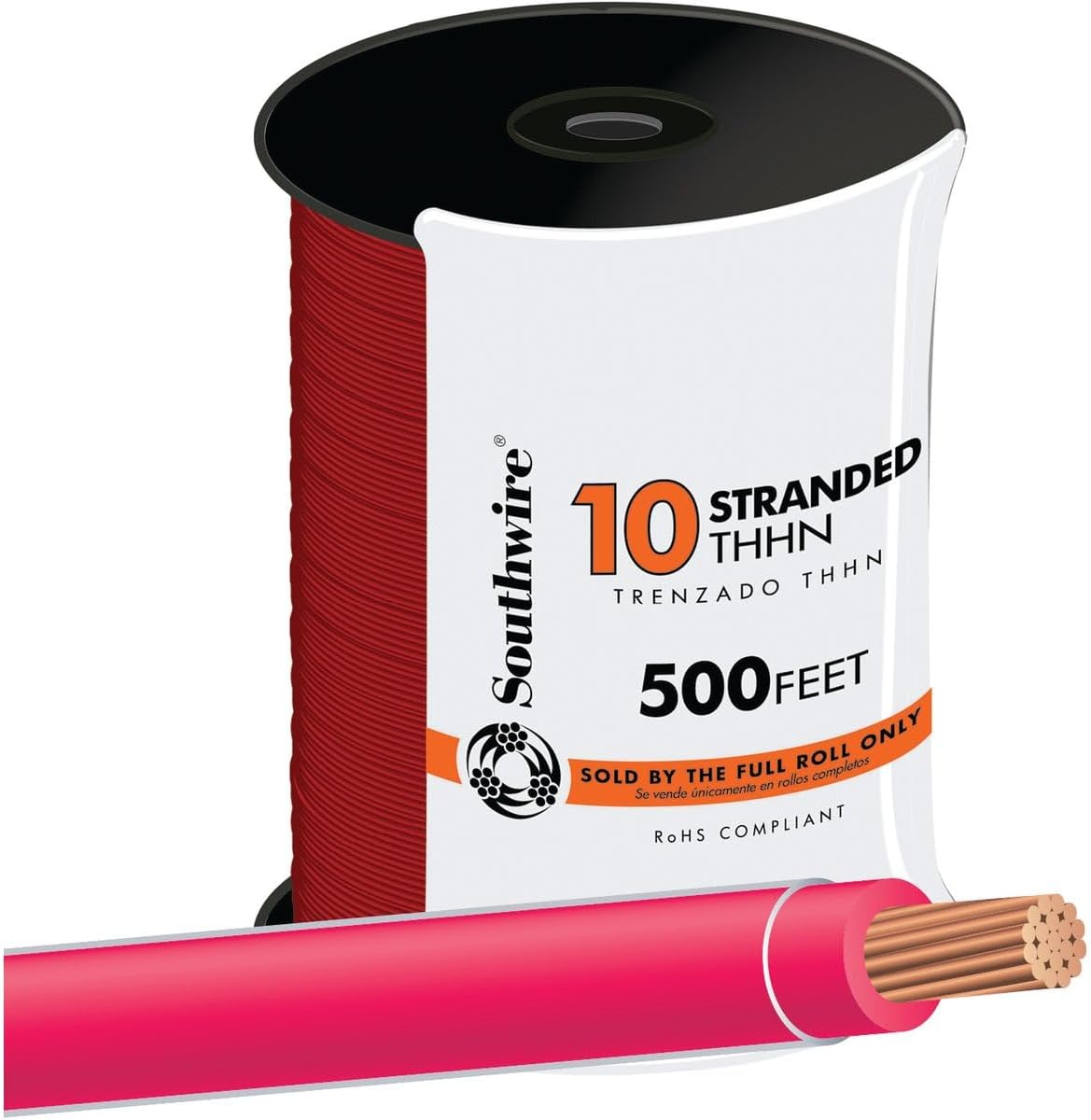


As an Amazon Associate, TestTalkHQ earns from qualifying purchases. Product names, links, and images are exact populated rows from the site affiliate catalog.
Because the final usable ampacity is limited by the applicable terminal rating. The 90°C value can often be the starting point for adjustment and correction, but the corrected result cannot exceed the terminal-column limit.
No. Equipment grounding conductors do not normally carry load current and are excluded. Neutrals require a circuit-specific decision.
Yes. Ampacity is a thermal safety calculation; voltage drop is a resistance and performance calculation. Both must pass, and the larger required conductor controls.
No. Physical raceway fill and ampacity adjustment are separate checks. A conduit can pass physical fill and still require ampacity adjustment for more than three current-carrying conductors.
For panel-to-receptacle building wire, use nameplate input current with the Wire Gauge Calculator for Welders. Then use the canonical Welding Wire Gauge Chart to keep branch wire, extension cords, welding leads, and MIG/TIG filler sizes separate.