Voltage Drop vs. Ampacity
Two separate calculations. Both have to pass. Here’s how to do them correctly and what to do when they conflict.
Ampacity tells you the wire won’t overheat. Voltage drop tells you the load will actually get enough voltage. They use different formulas, reference different NEC sections, and both set a floor on wire size — the larger gauge wins.
Use the Voltage Drop Calculator and Wire Ampacity & Derating Calculator together for complete wire sizing.

What Ampacity Is and What Controls It
Ampacity is defined in NEC Article 100 as the maximum current a conductor can carry continuously without exceeding its temperature rating. That temperature rating lives in the insulation — 60°C, 75°C, or 90°C depending on the wire type. Exceed the temperature limit and the insulation degrades, becomes brittle, and eventually fails. Ampacity is fundamentally a thermal problem: how much heat can this wire generate without cooking its own insulation?
Four variables control ampacity in practice:
Conductor size. A larger cross-section has lower resistance per foot, generates less heat at the same current, and dissipates that heat across more surface area. This is why 2 AWG carries more current than 12 AWG — not because of any magical property of thick wire, but because there is more copper to spread the heat.
Insulation temperature rating. NEC 310.15(B)(16) gives you three columns — 60°C, 75°C, and 90°C. THHN/THWN-2 is rated 90°C; however, the ampacity you actually use is limited by the temperature rating of the terminations, which are almost always rated 75°C on equipment up to 100 amps and may be 60°C on older or lighter equipment. You can have 90°C wire and still be limited to the 75°C column ampacity because the termination can't handle the heat the wire would generate at 90°C ampacity levels.
Conduit fill and bundling. When multiple current-carrying conductors share a conduit, they add heat to each other. NEC 310.15(C)(1) requires derating: 4–6 conductors at 80%, 7–9 at 70%, 10–20 at 50%, and so on down to 35% for 41 or more. A 4 AWG conductor rated 85A at 75°C drops to 42.5A after 50% derating when it shares conduit with eleven other current-carrying conductors. This is not a footnote — it is a hard code requirement that can double or triple the required wire size on dense conduit runs.
Ambient temperature. NEC 310.15(B)(2) provides correction factors for ambient temperatures above 30°C (86°F). Wire run in a boiler room, an attic in a hot climate, or alongside heat-producing equipment operates in a higher baseline temperature environment. The correction factors reduce allowable ampacity to account for the reduced ability to dissipate heat into a warmer surrounding. In an environment averaging 50°C ambient, a 75°C-rated conductor is working with only 25°C of thermal margin instead of 45°C — ampacity drops accordingly.
What Voltage Drop Is and What Controls It
Voltage drop has nothing to do with heat or insulation ratings. It is an Ohm's Law problem: V = I × R. Resistance is fixed by the conductor material and gauge. Current is fixed by the load. Run length multiplies both. The result is voltage lost in the conductors before it reaches the equipment.
Three variables control voltage drop:
Conductor resistance. Copper has lower resistivity than aluminum. Within copper, smaller AWG numbers mean larger cross-sections and lower resistance per foot. 4 AWG copper has a resistance of 0.308 Ω per 1,000 feet. 10 AWG has 1.24 Ω per 1,000 feet — four times as much. That ratio directly multiplies into voltage drop.
Current. Double the load current and you double the voltage drop at the same gauge and length. A circuit loaded to 40 amps drops twice the voltage of the same circuit loaded to 20 amps. This is why voltage drop on long runs is calculated at the actual expected load current, not the breaker rating — a 50-amp circuit that normally carries 30 amps drops 40% less voltage than one running at 50 amps.
Run length. The formula accounts for the round trip: every foot of conductor adds resistance on both the hot leg going out and the return conductor coming back. A 200-foot one-way run has 400 feet of total conductor in the circuit. Voltage drop scales linearly with length — double the run and you double the drop.
Temperature affects conductor resistance slightly (copper resistance increases roughly 0.4% per degree Celsius), but this is a secondary effect. The primary variables are gauge, current, and length.
Why These Are Two Completely Separate Calculations
Ampacity sets a floor on wire size based on heat. Voltage drop sets a floor on wire size based on resistance. They use different formulas, reference different NEC sections, and respond differently to the same variables. The only thing they share is that both improve when you use a larger conductor — but a larger conductor for one reason may or may not be adequate for the other.
Conduit fill illustrates the disconnect perfectly. Pulling more circuits through a conduit forces you to derate ampacity, which requires larger wire. But larger wire has lower resistance, which also improves voltage drop. The derating problem and the voltage drop problem push in the same direction — toward larger wire — but at completely different rates. You cannot solve one by solving the other. Both calculations must pass independently, and the larger of the two required gauges is what you install.
The correct sequence: find the minimum gauge that satisfies ampacity (accounting for derating, ambient temperature, and continuous load factors), then calculate voltage drop on that minimum gauge. If voltage drop passes, you're done. If it doesn't, upsize until it does. After upsizing for voltage drop, the larger wire will always satisfy ampacity — but if the conduit fill situation is complex, verify that the upsized wire doesn't introduce a new derating scenario that wasn't part of the original calculation.
Common Mistake 1 — Sizing for Ampacity and Ignoring Voltage Drop
This is by far the more common error. An electrician pulls wire for a 50-amp circuit 200 feet away, installs the NEC-minimum 8 AWG, and moves on. The breaker is correctly sized, the terminations are correct, the wire gauge matches the ampacity table. Inspection passes. Then the compressor in the shop struggles to start under load. The welder bogs down at high output settings. The air conditioner runs constantly without pulling the space down to temperature. Everything looks right on paper and nothing performs right in the field.
The voltage drop on 8 AWG at 50 amps over 200 feet on a 240V circuit:
VD = 2 × 0.778 Ω/1,000ft × 50A × 200ft / 1,000 = 15.56 volts — 6.5% of 240V
The equipment is running on 224V instead of 240V. Every motor on that circuit starts harder, runs hotter, and ages faster. The root cause is a conductor sized correctly for ampacity and not at all for the run length.
Common Mistake 2 — Oversizing for Voltage Drop Without Checking Derating
The reverse problem is less common but shows up on commercial work where electricians upsize aggressively for voltage drop on long runs, then bundle those larger conductors in shared conduits without revisiting the derating math.
Scenario: a shared conduit carrying twelve current-carrying conductors — six two-wire 240V circuits. NEC 310.15(C)(1) requires 50% derating for 10 to 20 conductors. An electrician sizes one of those circuits at 8 AWG to hit the voltage drop target on a 30-amp, 100-foot run. 8 AWG at 75°C is rated 50A. After 50% derating: 50A × 0.50 = 25A available ampacity — not enough for a 30-amp circuit.
The 8 AWG wire that solved the voltage drop problem now fails ampacity due to conduit fill. The correct approach is to derate first, find the ampacity-compliant minimum under the actual installation conditions, then layer the voltage drop calculation on top. In this case, working backwards: need 30A after 50% derating, so start with wire rated at 60A before derating — 4 AWG (85A rated, derated to 42.5A, which covers 30A with margin). Then check voltage drop on 4 AWG for the run in question.
How to Run Both Calculations Correctly
The practical workflow has five steps:
Step 1 — Establish base ampacity requirement. Identify the breaker size. If the load is continuous (operates for 3+ hours), multiply the continuous load by 125% per NEC 210.19(A)(1). A 30-amp circuit serving a continuous load needs conductors rated for 37.5 amps before derating.
Step 2 — Apply all derating factors. Count current-carrying conductors in the conduit. Check ambient temperature. Verify termination temperature ratings. Apply all applicable derating factors from NEC 310.15. The result is the minimum conductor ampacity you need from the table before installation conditions reduce it.
Step 3 — Find the ampacity-minimum gauge. Using NEC 310.15(B)(16) at the appropriate temperature column, find the smallest AWG that meets the derated ampacity requirement. This is your floor.
Step 4 — Calculate voltage drop on that floor gauge. Use the run length, actual load current, and conductor gauge to calculate voltage drop. For single-phase: VD = (2 × K × I × L) / CM, where K is 12.9 for copper. For three-phase: replace 2 with 1.732. The Voltage Drop Calculator at TestTalkHQ handles this directly — enter your gauge, run length, current, and supply voltage and it returns both the drop in volts and as a percentage against the 3% and 5% thresholds.
Step 5 — Reconcile. If the ampacity-minimum gauge hits the voltage drop target, install that gauge. If it doesn't, step up gauge until voltage drop passes. Use the Wire Ampacity & Derating Calculator at TestTalkHQ to model the full ampacity calculation — including conduit fill count, ambient temperature correction, and continuous load factor — before applying the voltage drop check on top. Both tools together cover the complete wire sizing decision.
Practical Decision Flowchart
When both calculations need to pass, work in this order every time:
Ampacity first. Derating factors can dramatically increase required conductor size and they are mandatory — no amount of good voltage drop performance saves a conductor that overheats because conduit fill wasn't accounted for. Get the ampacity-minimum gauge right before touching the voltage drop calculation.
Voltage drop second. Once you have the ampacity-minimum gauge, run the voltage drop at the actual expected load current (not the breaker size unless the circuit will truly be loaded to its rating). If the drop is within 3% for branch circuits and 3% on feeders, you're done.
When they conflict: upsize to satisfy voltage drop. The larger gauge will have more than adequate ampacity since you started from the ampacity minimum. The one exception is when upsizing for voltage drop creates a conduit fill situation that wasn't present at the smaller gauge — confirm that the upsized wire still fits the conduit without triggering additional derating requirements that would push you to yet another size up.
When conduit fill is the binding constraint: If the required gauge for both ampacity and voltage drop is so large that it won't fit an existing conduit, or creates a fill percentage violation, the solution is either a larger conduit, parallel conductors, or splitting the circuit. Parallel conductors halve the effective resistance per run (improving voltage drop) and each conductor only needs to carry half the load (improving ampacity margin).
Real Examples with Numbers
200-Foot 50A Welder Circuit on 240V
A MIG welder on a 50-amp, 240V circuit running 200 feet to a detached shop. The welder's actual input draw at working output is 40 amps. The circuit runs in its own conduit — no derating required. Terminations are 75°C rated.
Ampacity check: 50-amp breaker → NEC minimum conductor at 75°C = 8 AWG (50A). Non-continuous load, so no 125% multiplier. Ampacity minimum: 8 AWG.
Voltage drop on 8 AWG at 40A, 200ft:
VD = 2 × 0.778 × 40 × 200 / 1,000 = 12.45V = 5.19% on 240V — fails 3%
Try 6 AWG at 40A, 200ft:
VD = 2 × 0.491 × 40 × 200 / 1,000 = 7.86V = 3.27% — still fails 3%
Try 4 AWG at 40A, 200ft:
VD = 2 × 0.308 × 40 × 200 / 1,000 = 4.93V = 2.05% ✓
Install 4 AWG. Ampacity minimum was 8 AWG. Voltage drop drove the wire size to 4 AWG — two full sizes larger. 4 AWG has an ampacity of 85A at 75°C, providing substantial headroom above the 50-amp breaker rating.
100-Foot 30A Dryer Circuit on 240V
A 240V dryer circuit, 30-amp breaker, 100-foot run to a laundry room addition. The dryer draws 24 amps at operating temperature. No shared conduit. 75°C terminations.
Ampacity check: 30-amp breaker → NEC minimum at 75°C = 10 AWG (35A). Non-continuous. Ampacity minimum: 10 AWG.
Voltage drop on 10 AWG at 24A, 100ft:
VD = 2 × 1.24 × 24 × 100 / 1,000 = 5.95V = 2.48% ✓
At actual operating current (24A) the 10 AWG passes. But at full nameplate current (30A):
VD = 2 × 1.24 × 30 × 100 / 1,000 = 7.44V = 3.10% — marginally over 3%
Whether to upsize depends on how the circuit will be used. A dryer rarely runs at full nameplate continuously; sizing to actual operating current is defensible. If you want margin at peak draw, upsize to 8 AWG (VD at 30A = 4.67V, 1.95%) — the cost difference on a 100-foot run is modest and the dryer will run cooler at its heating elements during peak demand cycles. Either 10 AWG or 8 AWG is correct; the choice depends on how conservatively you're designing.
150-Foot 100A Subpanel Feed on 240V
A 100-amp subpanel 150 feet from the main panel in a residential shop. The feeder will be fully loaded at times — compressors, welders, and general shop loads running simultaneously. Assume 80A as a realistic continuous load scenario. 75°C terminations. Feeder runs alone in its own conduit.
Ampacity check: 100-amp breaker → NEC minimum at 75°C = 3 AWG (100A). For an 80A continuous load: 80A × 1.25 = 100A required ampacity → 3 AWG exactly meets it. For margin, 2 AWG (115A) is a common design choice on 100A feeders.
Voltage drop on 3 AWG at 100A, 150ft:
VD = 2 × 0.245 × 100 × 150 / 1,000 = 7.35V = 3.06% — fails 3% at full rated current
Voltage drop on 2 AWG at 100A, 150ft:
VD = 2 × 0.194 × 100 × 150 / 1,000 = 5.82V = 2.43% ✓
Voltage drop on 2 AWG at 80A continuous, 150ft:
VD = 2 × 0.194 × 80 × 150 / 1,000 = 4.66V = 1.94% ✓
Install 2 AWG. 3 AWG meets the ampacity requirement with no margin and misses the voltage drop recommendation at full load. 2 AWG provides ampacity margin (115A rated vs 100A breaker) and comfortably passes voltage drop at both the continuous operating load and peak draw. On a feeder that will serve shop loads where startup currents and simultaneous loads are common, 2 AWG is the correct choice on both calculations.
Frequently Asked Questions
If I upsize wire for voltage drop, do I need to upsize the breaker too?
No. The breaker is sized to protect the circuit and equipment, not to match the wire's full ampacity. You can and often should run wire that has more ampacity than the breaker rating — that is exactly what happens when you upsize for voltage drop. A 50-amp circuit protected by a 50-amp breaker that is wired with 4 AWG (rated 85A) is correctly installed: the breaker will trip at 50 amps long before the 4 AWG wire is stressed. The wire can handle more current than the breaker will ever allow, which is fine. Never upsize the breaker to match the wire when the purpose of upsizing the wire was voltage drop.
Does voltage drop affect ampacity calculations at all?
Not directly. Ampacity is governed by thermal limits — how much current causes how much heat in the conductor under the installation conditions. Voltage drop is a separate phenomenon governed by Ohm's Law. However, there is an indirect relationship through temperature: a conductor experiencing significant voltage drop is also dissipating heat (P = I² × R), and that heat contributes to the conductor's operating temperature, which affects its remaining thermal margin. In practice this effect is small and is not factored into standard ampacity calculations, but it is a reminder that both phenomena trace back to the same root cause: conductor resistance.
When should I run parallel conductors instead of upsizing to a single large conductor?
Parallel conductors — two or more conductors per phase connected at both ends — make sense when the required wire size for a single conductor is impractical to handle, terminate, or pull. NEC 310.10(H) permits parallel conductors in sizes 1/0 AWG and larger. On a run requiring 350 kcmil single conductors, two parallel sets of 3/0 AWG is the same total copper cross-section, more manageable to pull, and often easier to terminate. Parallel conductors also halve the effective resistance of the run, improving voltage drop proportionally. The constraint is that all parallel conductors must be the same length, same gauge, same material, and in the same raceway or in separate raceways with the same phase grouping — the NEC requirements for parallel conductors are specific and must be followed exactly.
My ampacity calculation says 6 AWG but my voltage drop calculation says 4 AWG. Which one do I use?
4 AWG — you always use the larger result. Both calculations set a minimum floor on conductor size, and you must clear both floors simultaneously. The larger required gauge is the answer because it is the only gauge that satisfies both constraints at the same time. 4 AWG satisfies the voltage drop requirement and has more than adequate ampacity since it exceeds the 6 AWG ampacity minimum. 6 AWG satisfies the ampacity requirement but fails voltage drop. There is no valid wire size between those two — you cannot split the difference. When two constraints conflict, the more restrictive one controls.
Recommended Wire Sizing Tools
Verify wiring, measure under load, and confirm run lengths before pulling wire
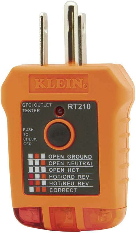
Klein Tools RT210 GFCI Outlet Tester
When troubleshooting a circuit that’s failing either an ampacity or voltage drop check, start by verifying the circuit is correctly wired. The Klein RT210 rules out open neutrals, reversed polarity, and missing grounds in seconds — basic wiring faults that can look like sizing problems until you check.
Check Price
Fluke 117 Digital Multimeter
Ampacity compliance is a design calculation, but voltage drop compliance can be verified with a meter. The Fluke 117 reads true RMS voltage under load — measure at the panel and at the far end simultaneously and you have your actual drop. If the number exceeds 3%, the circuit is undersized for the run regardless of what the ampacity table says.
Check Price
Klein Tools NCVT-6 Non-Contact Voltage Tester with Laser Distance
Safe conductor verification plus a built-in laser distance meter. Knowing exact run length before sizing wire eliminates the guesswork that causes undersized long runs. Measure it, calculate it, pull the right gauge the first time.
Check PriceAs an Amazon Associate, TestTalkHQ earns from qualifying purchases.
Why Both Calculations Are Required — Not Optional
Some electricians treat voltage drop as optional — something to check if the run is really long, but otherwise not worth the effort. That attitude produces installations that pass inspection and fail in service. The ampacity table tells you the wire won’t burn. It says nothing about whether the motor at the end of the circuit will start reliably, run at rated temperature, or last its designed service life. Voltage drop is the performance calculation. Ampacity is the safety calculation. Both are required for a circuit that works correctly, not just one that passes inspection. Skipping voltage drop on long runs is how you end up replacing motors and troubleshooting phantom problems for years.
The Conduit Fill Trap — When Upsizing Creates a New Problem
Upsizing conductors for voltage drop can create a conduit fill problem if you’re not tracking both simultaneously. NEC Table 1 in Chapter 9 limits conduit fill to 40% of interior area for three or more conductors. When you step up from 4 AWG to 2 AWG on all three phases of a three-phase circuit to fix a voltage drop issue, the conduit that was sized for 4 AWG may no longer accommodate 2 AWG. Check conduit fill every time you upsize for voltage drop. If the conduit is already in place and undersized for the larger wire, you’re either pulling new conduit or finding a different solution — sometimes a delta-wye transformer to boost voltage is more practical than repulling conduit.
Three-Phase Circuits — How Voltage Drop Calculation Changes
The single-phase voltage drop formula uses a factor of 2 to account for the round-trip current path through hot and neutral conductors. Three-phase circuits use 1.732 (the square root of 3) instead, because the three phases share the return path and the geometry of three-phase current flow reduces the effective round-trip resistance. For the same conductor size, current, and run length, a balanced three-phase circuit drops significantly less voltage than a single-phase circuit — roughly 13% less. This is one of the practical advantages of three-phase power for long distribution runs in commercial and industrial facilities. Always use the correct formula for the system type, or your voltage drop calculations will be wrong by a consistent margin.
When to Upsize and When to Redesign
Sometimes the right answer to a voltage drop problem isn’t larger wire — it’s a different circuit architecture. A single 200-foot, 100-amp feeder that’s failing voltage drop by a wide margin might be better served by a subpanel at the midpoint, cutting the effective run length in half for every branch circuit it serves. A long 120V circuit that keeps dropping voltage might be better redesigned as a 240V circuit serving the same load at half the current. Upsizing wire solves a voltage drop problem on one circuit. Redesigning the distribution architecture solves it for every circuit in the area. When the voltage drop calculation requires more than two AWG sizes of upsizing, it’s worth stepping back and asking whether the circuit layout itself is the problem.