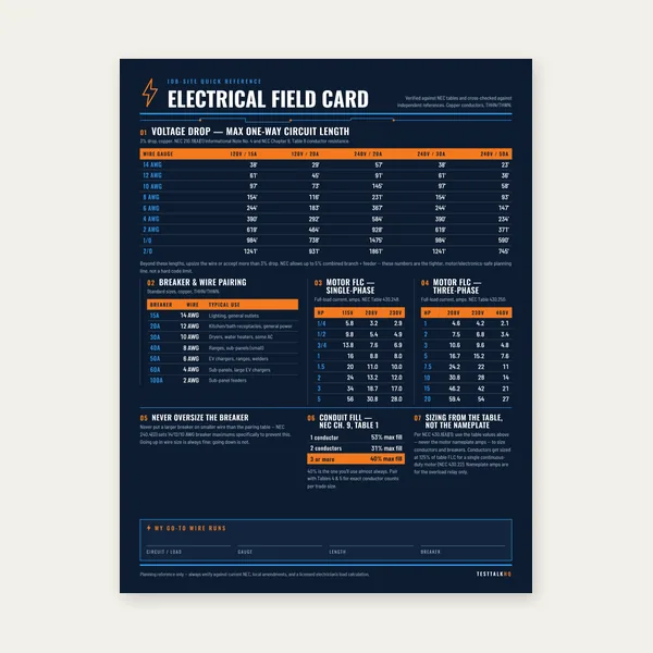
Electrical Reference Card
One page. Voltage drop lengths, breaker and wire pairing, motor FLC.
$3.99
BuyDiagnose when measured drop fights the calculator, equipment underperforms despite a “passing” calc, long feeds still sag, multi-wire branch mistakes hide imbalance, and meters lie about where you probe
Not another how-to for V = I × R. Pair this page with the Advanced Voltage Drop Calculator when paper numbers look fine and the job still fails. For definition and formula walkthroughs use Voltage Drop Explained and How to Calculate Voltage Drop — this guide stays on diagnosis.
Diagnosing a flexible cord run? Start with the extension cord voltage drop guide, then test the actual AWG, length, and load with the extension cord voltage drop calculator.
Use this when the lights dim, a motor stalls, or your DMM reading refuses to match the spreadsheet.
| Problem | What it usually means | First fix | Next tool |
|---|---|---|---|
| Measured drop >> calculated | Extra resistance not in the model — loose lugs, corroded Al, wrong gauge actually pulled | IR / torque check terminations; verify AWG with mic/strip and panel schedule | Advanced VD Calculator |
| Calc “passes” but equipment dies | Calc used wrong current (nameplate, not inrush), ignored heat/ambient, or shared-neutral shift | Re-run at locked-rotor / peak amp; check ambient derate & MWBC loading | VD vs Ampacity |
| Long shop / pump / generator feed still sags | One-way length entered as total, Al resistivity ignored, or feeder+branch stacked | Use one-way feet × 2 for copper/Al formulas; model feeder then branch | Long Runs Guide |
| One MWBC leg bright, other dull / odd NECs | Shared neutral overloaded or open; phases unbalanced | Clamp neutral & each hot under load; never share neutrals across different multiwire systems carelessly | NEC VD Notes |
| Panel looks fine, receptacle dies under load | You measured source, not load end — or measured unloaded | Probe hot–neutral at load while running; compare to panel hot–neutral same phase | How to Calculate VD |
| Good voltage, tripped breaker / heat smell | Ampacity / connection failure, not volt-drop math | Stop chasing %VD — thermal path & torque first | VD vs Ampacity |
What it looks like: Spreadsheet or the advanced calculator says ~2–3% on the design gauge. Under load your meter shows 6–10% at the receptacle, well pump, or welder outlet. Idle voltage looks almost normal.
Why it happens (extra R the formula never saw): Textbook drop is I × Rconductors. Real drop is I × (Rcopper/Al + Revery lug, splice, breaker, receptacle, and oxidised connection). Any series contact resistance that was ignored in the model shows up as “mystery” volts once current flows.
Likely causes checklist:
Fixes:
What it looks like: NEC-flavoured 3% / 5% recommendation is green on paper. Compressors hard-start, VFD trips on undervoltage, LED drivers flicker on tip-up cycles, welders bog only when other loads share the feeder.
What the calculator is not doing for you:
Fixes:
What it looks like: Detached garage welder, barn pump, or generator transfer still brown-outs even after “we upsized.” Spreadsheet used 200 ft when the trench is 200 ft one-way — or Al feeders were treated like copper.
Common field errors unique to long work:
Fixes:
What it looks like: One countertop leg runs heaters fine; the other flats out or trips GFCI/AFCI. Neutral feels hot. Line-to-neutral volts unequal under load though both “circuits” share a handle-tied breaker.
Why MWBC math bites voltage drop: On a proper 240/120 MWBC, return currents partially cancel in the shared neutral. If phases land on the same leg, or a multiwire pair is broken into two unrelated circuits, the neutral carries more than the model assumed. Calculators that treat each 120 V circuit as an independent round-trip overcount or undercount depending on how you entered the neutral.
Likely causes:
Fixes:
What it looks like: “We checked voltage — it’s fine.” Probe was at the panel with tools plugged in far away, or measured unloaded receptacles. Calc and field numbers will never reconcile.
Correct differential method:
Common measurement mistakes:
Related how-to: formula and percent method live in How to Calculate Voltage Drop; code notes in NEC Voltage Drop Requirements.
Undervoltage that clears when you upsize is a resistance problem. Heat, smell, breaker trips on continuous load with decent voltage are often ampacity / termination problems. Run both calcs — the larger conductor wins. Full walkthrough: Voltage Drop vs Ampacity.
One page. Voltage drop lengths, breaker and wire pairing, motor FLC.
$3.99
Buy
15 pages. Ampacity, corrections, voltage drop, motor circuits, conduit fill.
$12.99
Buy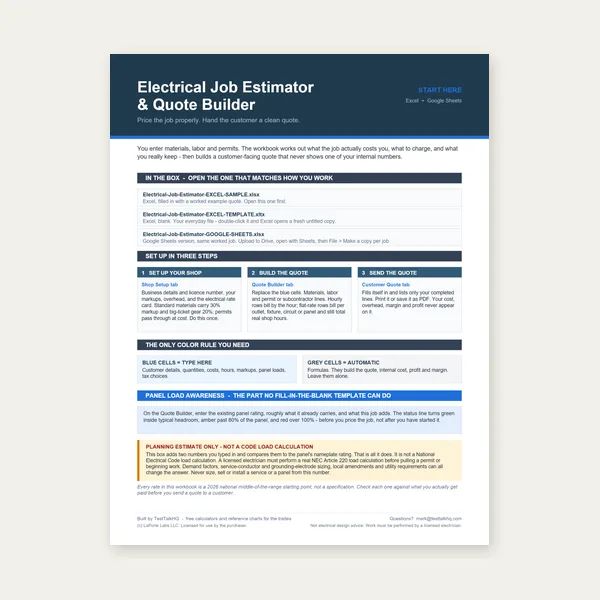
Quote electrical work and flag panel headroom before you price it.
Excel or Google Sheets. Best on a computer.
$29.00
Buy
Card, 15-page guide and the estimator workbook. All six files.
Excel or Google Sheets. Best on a computer.
$34.99
$45.98 if bought separately — save $10.99
BuyCheckout opens in a new tab.
Six electrical picks from the TestTalkHQ affiliate catalog — meters, clamp, fish tape, stripper, and anti-oxidant for aluminium terminations


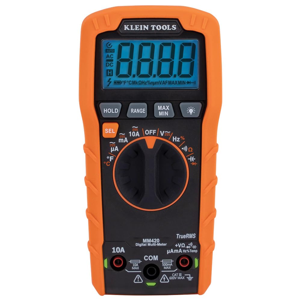
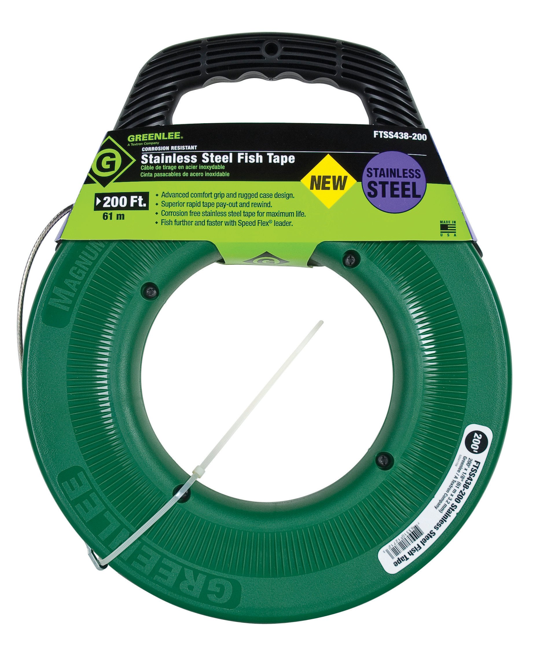


As an Amazon Associate, TestTalkHQ earns from qualifying purchases. Always follow manufacturer torque and listing requirements — compound is not a substitute for the correct connector.
Extra series resistance — loose lugs, oxidised aluminium, wrong installed gauge, device contacts — is outside most conductor-only models. Fix terminations and verify AWG before more upsizing.
Yes. Steady-state amp assumptions miss locked-rotor / start current, soft sources, and ambient heat. Re-run at peak amps and measure under start.
Compare source and load on the same phase under the same load. Hot-to-neutral (120 V) or line-to-line (240 V). Source-only checks miss the run.
Yes. Shared neutrals and wrong phasing alter return current. Clamp the neutral and confirm opposite phases before trusting a single-phase round-trip model.
Both floors apply independently; install the larger required gauge. Walkthrough: Voltage Drop vs Ampacity.
They are informational notes in many editions, not automatic Chapter 2 absolute mandates. Design to them for equipment performance; confirm your AHJ / project spec: NEC voltage drop notes.
If the conductor, breaker, temperature column, neutral count, or final derated result still disagrees with the field, use Wire Ampacity Troubleshooting. Re-run the numbers with the Wire Ampacity & Derating Calculator and review the method in Wire Ampacity and Derating Explained.