Voltage Drop in Long Wire Runs
How to size wire for shops, outbuildings, and RVs — with real numbers and a sizing table.
Long wire runs change the math entirely. Ampacity tables tell you what won’t overheat — voltage drop tells you what will actually work at the far end. This guide covers 3%/5% limits, wire sizing for 50A–100A feeders at 100–300 feet, and real scenarios for shops, outbuildings, welders, and RV shore power.
Use the Voltage Drop Calculator for instant numbers on your gauge, run length, and load.

Why Long Wire Runs Are a Different Problem
On a 15-amp circuit feeding an outlet six feet from the panel, voltage drop is a non-issue. The run is short, the resistance is negligible, and every volt that leaves the breaker arrives at the receptacle. Extend that same circuit to 150 feet and the math changes entirely. The wire that was never a problem becomes the limiting factor — not because the breaker is wrong or the load changed, but because resistance accumulates with every foot of conductor, and a long run has a lot of feet.
This is the part most electricians size correctly on short runs and undersize on long ones. The NEC ampacity tables tell you what gauge wire won't overheat at a given current. They do not tell you what gauge will deliver acceptable voltage at the far end of a 200-foot run. Those are two separate questions with two separate answers, and on long runs the voltage drop answer always calls for larger wire than the ampacity answer does.
The relationship is direct: double the run length and you double the voltage drop at the same current. Double the current and you double the drop at the same run length. The only variable working in your favor is wire gauge — bump up two AWG sizes and you cut resistance by roughly 37%. On a 300-foot feeder to an outbuilding, you may need to upsize three or four AWG beyond the minimum ampacity rating just to keep voltage at the far end within acceptable limits.
The 3% and 5% Guidelines — What They Mean in Practice
The NEC states in Informational Note No. 1 to Section 210.19(A) that a voltage drop of 3% or less on branch circuits is recommended, and that the combined drop across the feeder and branch circuit should not exceed 5%. These are recommendations, not enforceable code requirements in most jurisdictions — but they represent the engineering baseline that keeps equipment running properly and within its design parameters.
In practice, 3% on a 120V circuit means you can afford to lose 3.6 volts between the panel and the load. On 240V, 3% allows 7.2 volts of drop. Everything beyond that starts degrading equipment performance. Motors run hotter, start harder, and fail earlier. Variable-speed drives and inverters fault out rather than run at reduced voltage. Battery chargers and electronics either slow down or generate heat trying to compensate.
The 5% combined limit is the absolute outer boundary for a system that is going to perform acceptably. A feeder that drops 3% and a branch circuit that drops another 2% lands right at 5% combined — still within the recommendation, but with zero margin. Any load variation or additional resistance from a loose termination or aging wire pushes you over. Design to 3% on long feeders when you can. Reserve the 5% combined limit for short branch circuits on an already-marginal feeder, not as a target.
How to Calculate Wire Size for Long Runs
The voltage drop formula for single-phase circuits is:
VD = (2 × K × I × L) / CM
Where VD is the voltage drop in volts, K is 12.9 for copper or 21.2 for aluminum, I is the load current in amps, L is the one-way run length in feet, and CM is the circular mil area of the conductor. The factor of 2 accounts for both the hot conductor and the return path. For three-phase circuits, replace 2 with 1.732.
Working through a quick example: a 30-amp circuit, 150 feet one-way, on 8 AWG copper (16,510 CM):
VD = (2 × 12.9 × 30 × 150) / 16,510 = 116,100 / 16,510 = 7.03 volts
On a 240V circuit, that is 2.93% — just inside the 3% limit. On a 120V circuit, the same wire and run would drop 5.86% — nearly double the recommendation. This is why moving loads to 240V wherever possible is one of the most effective strategies for managing voltage drop on long circuits.
Rather than working through the formula manually for every job, use the Voltage Drop Calculator at TestTalkHQ. Enter your wire gauge, conductor material, one-way run length, current draw, and supply voltage and it returns both the drop in volts and as a percentage, plus the minimum gauge needed to hit 3% on that exact run.
Wire Sizing Table for Long Runs — 240V Copper
The table below shows the minimum copper AWG needed to stay at or below 3% voltage drop on a 240V circuit. These figures are for voltage drop only — always verify the selected gauge also meets NEC 310.15 ampacity requirements for your installation conditions. Where the ampacity minimum calls for a larger gauge than the table shows, use the larger gauge.
| One-Way Run | 20A Circuit | 30A Circuit | 50A Circuit | 100A Circuit |
|---|---|---|---|---|
| 50 ft | 12 AWG | 10 AWG | 8 AWG | 2 AWG |
| 100 ft | 10 AWG | 8 AWG | 6 AWG | 1 AWG |
| 150 ft | 8 AWG | 6 AWG | 4 AWG | 1/0 AWG |
| 200 ft | 8 AWG | 6 AWG | 4 AWG | 1/0 AWG |
| 300 ft | 6 AWG | 4 AWG | 2 AWG | 2/0 AWG |
Note that 150-foot and 200-foot runs often land on the same gauge — not a typo. The additional 50 feet pushes the drop higher but not enough to cross into the next gauge requirement at those current levels. At 300 feet, everything jumps, and a 100-amp run at 300 feet requires 2/0 AWG copper to stay under 3%.
Real-World Scenarios with Real Numbers
100-Foot Shop Subpanel on a 240V 50A Circuit
This is one of the most common shop electrical projects: adding a subpanel in a detached garage or shop fed from the main panel 100 feet away. The minimum ampacity for a 50-amp circuit is 8 AWG copper (50A at 75°C terminations). At 100 feet, 8 AWG drops this:
VD = 2 × 0.778 Ω/1000ft × 50A × 100ft / 1000 = 7.78 volts = 3.24% on 240V
That is over the 3% recommendation. Step up to 6 AWG and the drop becomes:
VD = 2 × 0.491 × 50 × 100 / 1000 = 4.91 volts = 2.05%
The correct answer for a 50-amp subpanel at 100 feet is 6 AWG copper — one size above the ampacity minimum. The additional cost is modest for a 100-foot run. The difference in performance when starting a compressor, running a welder, and having the lights on simultaneously is not modest.
200-Foot Outbuilding Feed on a 240V 100A Circuit
Running a 100-amp feeder 200 feet to a barn, shop, or second structure is where wire size decisions get expensive if you get them wrong. The NEC ampacity minimum for 100 amps is 3 AWG copper (100A at 75°C) or 2 AWG for a 15% continuous load margin. Check the voltage drop on 2 AWG at 200 feet:
VD = 2 × 0.194 × 100 × 200 / 1000 = 7.76 volts = 3.23% on 240V
Over the limit. Step to 1 AWG:
VD = 2 × 0.154 × 100 × 200 / 1000 = 6.16 volts = 2.57% ✓
Step to 1/0 AWG for comfortable margin:
VD = 2 × 0.122 × 100 × 200 / 1000 = 4.88 volts = 2.03% ✓
The right answer for a 100-amp feeder at 200 feet is 1/0 AWG copper. If you're pulling it through underground conduit, you do this once. The cost difference between 1 AWG and 1/0 AWG over 200 feet is a few hundred dollars. Digging up the conduit and repulling because you undersized is several times that. This is also where aluminum feeders earn their place — 2/0 AWG aluminum achieves similar performance to 1/0 copper at lower material cost, and direct-burial aluminum SER is a standard and code-compliant choice for underground outbuilding feeds.
50-Foot Extension Cord Running a Welder
Welders are among the most abusive loads for extension cord voltage drop. A 240V MIG welder pulling 40 amps of input current on a 50-foot 10 AWG extension cord:
VD = 2 × 1.24 × 40 × 50 / 1000 = 4.96 volts = 2.07% ✓
10 AWG handles it. But if someone grabs a 12 AWG "heavy duty" cord instead:
VD = 2 × 1.98 × 40 × 50 / 1000 = 7.92 volts = 3.3% — over the limit, and that cord is not rated for 40 amps regardless of the voltage drop math.
On 14 AWG — the kind someone buys at a hardware store without checking the gauge:
VD = 2 × 3.14 × 40 × 50 / 1000 = 12.56 volts = 5.23% — more than 5% of your supply voltage gone in the extension cord, and the cord is running well above its current rating. This is how extension cords catch fire and welders arc erratically.
The minimum for a 240V welder extension cord on a 50-amp circuit is 8 AWG, and 6 AWG is better if you weld for more than a few minutes at a stretch. Standard "heavy duty" 12 AWG extension cords are not welding cords.
RV Shore Power Hookup 75 Feet from the Pedestal
A 30-amp RV circuit at 120V is the standard residential hookup. The standard 30-amp RV power cord is 10 AWG and typically 25–30 feet long. At 30 feet it performs fine. At 75 feet with a 30-amp draw, the math turns against you:
VD = 2 × 1.24 × 30 × 75 / 1000 = 5.58 volts = 4.65% on 120V — well over the 3% recommendation
Step to 8 AWG for the 75-foot run:
VD = 2 × 0.778 × 30 × 75 / 1000 = 3.50 volts = 2.92% ✓ — just inside 3%
For a 50-amp RV (120/240V), the situation is better because the current splits across two legs. At 50 amps on 240V over 75 feet on 8 AWG:
VD = 2 × 0.778 × 50 × 75 / 1000 = 5.84 volts = 2.43% ✓
The takeaway for RV setups: a standard 25-foot RV cord is fine at the pedestal. Anything beyond 50 feet requires stepping up the gauge — 10 AWG for 30A up to about 50 feet, 8 AWG beyond that. A voltage drop at the RV affects the air conditioner compressor first and most noticeably, since it draws close to its rated amperage at startup and runs continuously.
When to Upsize Wire vs. When to Split the Circuit
Upsizing wire is the right answer when you have a single load that needs to be close to its rated voltage — a motor, a subpanel, a welder — and the run is fixed. One feeder, one wire size decision, solved.
Splitting the circuit makes more sense when the actual problem is that you have too many loads spread across a long run, each individually modest but collectively large. A 100-foot shop circuit feeding a grinder, a drill press, and several 20-amp receptacles is not a single-load problem. Running individual 20-amp circuits to the areas where each tool is used is often more practical than running one heavily loaded 50-amp circuit and upsizing the wire to compensate. Shorter individual branch circuits from a local subpanel beat one overloaded long feeder in both voltage drop and circuit protection.
The decision point is usually this: if the load is one heavy piece of equipment (compressor, welder, subpanel), upsize the wire to it. If the load is distributed across multiple locations in a shop or building, install a subpanel at the midpoint of the space and run short branch circuits from it. A well-placed 60-amp subpanel 50 feet from the main panel almost always outperforms a heavily loaded 200-foot circuit trying to serve a whole shop with one home run.
For any scenario that isn't obvious from the table above, run it through the Voltage Drop Calculator before pulling wire. Plug in the actual load, the actual run length, and both the ampacity-minimum gauge and the next size up — then compare the percentage drop on each. The time cost of that calculation is measured in seconds. The cost of undersizing a 200-foot underground feeder is measured in days of excavation and hundreds of dollars of materials.
Frequently Asked Questions
Does voltage drop on a feeder add to voltage drop on the branch circuit?
Yes, and this is exactly what the NEC's 5% combined limit addresses. If your 200-foot feeder to an outbuilding drops 2.5% of supply voltage, and then a 50-foot branch circuit inside the outbuilding drops another 2%, the total drop from the main panel to the load at the end of that branch circuit is 4.5% — still within the combined 5% limit, but with almost no margin. This is why long feeders should be designed to 2–2.5% drop when possible, leaving headroom for the branch circuits they serve.
Can I run aluminum wire to reduce the cost of a long feeder?
On feeders requiring 2 AWG copper or larger, aluminum is a legitimate and code-compliant choice that significantly reduces material cost. Aluminum has about 61% of copper's conductivity, so you size it two AWG steps larger to achieve equivalent performance — 1/0 AWG aluminum is roughly equivalent to 2 AWG copper in both ampacity and resistance. Use only connectors and terminations rated AL/CU, apply antioxidant compound at all connections, and torque lugs to spec. For underground conduit runs to outbuildings or for service entrance conductors, aluminum in conduit is standard industry practice.
My welder manual says it needs a 50-amp circuit. Does that mean it actually draws 50 amps?
No. The circuit rating is the minimum breaker size required to handle the welder's peak inrush and maximum duty cycle without nuisance tripping. Most 240V MIG and stick welders running at a practical output level draw 30–45 amps of input current, not 50. The voltage drop you actually experience depends on the current the welder is pulling at the moment — which varies with output setting, wire speed, and duty cycle. For voltage drop calculations on a welder circuit, use the actual input current at your typical output settings, not the circuit breaker rating. Your welder's owner's manual lists input current at various output levels.
How do I know if I'm already losing voltage on an existing long run?
Measure it under load. Use a multimeter to check voltage at the panel and at the far end receptacle or load simultaneously — or measure at the panel, note the reading, then measure at the far end while the load is running and compare. The difference is your actual voltage drop. If it exceeds 3% of your supply voltage under a realistic load, the circuit is undersized for the run. A voltage reading at the panel of 122V and 109V at the far end under load is a 10.7% drop — more than three times the recommendation — and an explanation for why the motor there keeps overheating.
Recommended Voltage Testing Tools
Verify source wiring, measure under load, and measure run length before you pull wire
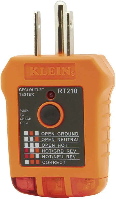
Klein Tools RT210 GFCI Outlet Tester
Before pulling wire on a long run, verify the source circuit is correct. The Klein RT210 checks for open ground, open neutral, open hot, reversed polarity, and GFCI function in seconds. A simple check that rules out panel wiring issues before you commit to a long run of expensive copper.
Check Price
Fluke 117 Digital Multimeter
Verify actual voltage at the load end of a long run under operating conditions. The Fluke 117 reads true RMS voltage — check at the panel, check at the far end under load, and the difference is your real-world voltage drop. Knowing the actual number tells you whether your wire sizing decision was right or needs to be corrected before equipment starts failing.
Check Price
Klein Tools NCVT-6 Non-Contact Voltage Tester with Laser Distance
Confirm live conductors safely and use the built-in laser distance meter to measure run lengths before calculating wire size. Knowing the actual distance rather than estimating it is the difference between a wire sizing calculation that’s right and one that’s 20 feet short of reality.
Check PriceAs an Amazon Associate, TestTalkHQ earns from qualifying purchases.
Underground Conduit Runs — Size It Right Before You Bury It
Underground conduit runs to outbuildings, shops, and barns are the most expensive voltage drop mistakes to fix. Once the trench is backfilled and the concrete is poured, upsizing the wire means excavating the entire run — a job that costs many times what the larger wire would have cost originally. Before any underground run, calculate the voltage drop at the expected load and at the full circuit rating. If you’re on the fence between two gauge sizes, use the larger one. The cost difference between 100 feet of 1 AWG and 1/0 AWG copper is modest. The cost of digging it up is not.
Why Aluminum Makes Sense on Long Feeder Runs
Aluminum wire gets a bad reputation from the aluminum branch circuit wiring problems of the 1960s and 70s — small-gauge aluminum in 15 and 20-amp circuits with incompatible devices. That problem has nothing to do with large-gauge aluminum feeders, which are standard practice in commercial and industrial electrical work. On runs requiring 2 AWG copper or larger, aluminum is lighter, significantly cheaper, and code-compliant with the right connectors and antioxidant compound. A 200-foot, 100-amp underground feeder in aluminum costs less than half what copper costs and performs equivalently when sized correctly — typically two AWG steps larger than the copper equivalent.
Subpanel Location Matters More Than Wire Size
The most cost-effective solution to voltage drop in a large shop or building often isn’t upsizing the wire — it’s moving the subpanel. A 60-amp subpanel installed at the midpoint of a shop serves every corner of the space with short branch circuits, eliminating the long individual runs that create voltage drop problems. One properly sized feeder to a central subpanel almost always outperforms multiple long branch circuits running from a distant main panel. If you’re planning a shop buildout, spend time on subpanel location before you spend money on wire. Getting the panel placement right reduces the total wire cost and eliminates voltage drop as an ongoing problem.
Voltage Drop on 120V vs 240V Circuits — Why It Matters Which You Use
The same load on 240V draws half the current it would on 120V, which means half the voltage drop across the same wire. A 4,800-watt air compressor on a 120V circuit draws 40 amps and drops voltage aggressively on any run over 50 feet. The same compressor on a 240V circuit draws 20 amps and has a quarter of the voltage drop at the same distance. Every motor, compressor, welder, and heavy tool that can be served at 240V should be — especially in a shop with long runs. The voltage drop advantage of 240V over 120V on long circuits is one of the strongest practical arguments for wiring a shop at 240V from the start.