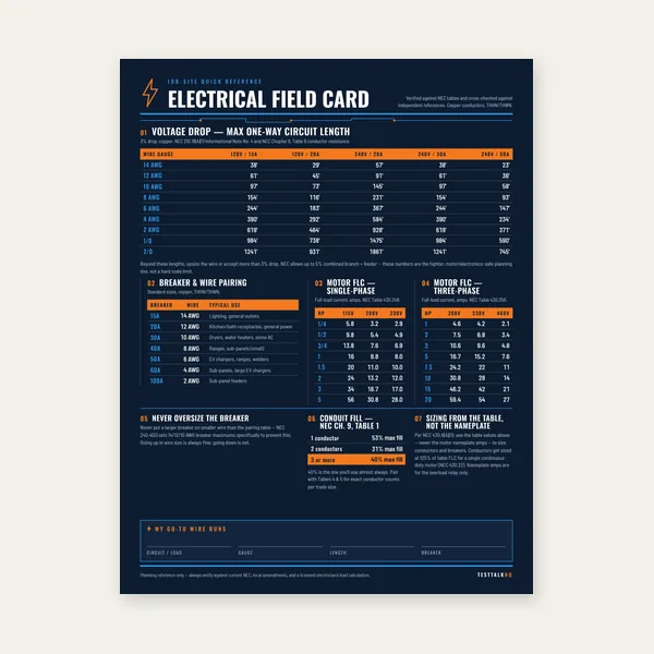
Electrical Reference Card
One page. Voltage drop lengths, breaker and wire pairing, motor FLC.
$3.99
BuyEnter line voltage, line current, and power factor to calculate apparent power, real power, reactive power, and the power triangle for any three-phase system.
Calculate kVA, kW, kVAR, phase voltage, and phase current for Wye or Delta systems. See the Three-Phase Power Guide for formulas, voltage levels, and field troubleshooting.

| Quantity | Formula | Units |
|---|---|---|
| Apparent power | S = √3 × VL × IL | kVA (÷1000) |
| Real power | P = S × PF | kW |
| Reactive power | Q = √(S² − P²) | kVAR |
| Wye phase voltage | Vphase = VL / √3 | Volts |
| Delta phase voltage | Vphase = VL | Volts |
| Wye phase current | Iphase = IL | Amps |
| Delta phase current | Iphase = IL / √3 | Amps |
VL = line voltage (L-L) · IL = line current · PF = power factor (0–1)
One page. Voltage drop lengths, breaker and wire pairing, motor FLC.
$3.99
Buy
15 pages. Ampacity, corrections, voltage drop, motor circuits, conduit fill.
$12.99
Buy
Quote electrical work and flag panel headroom before you price it.
Excel or Google Sheets. Best on a computer.
$29.00
Buy
Card, 15-page guide and the estimator workbook. All six files.
Excel or Google Sheets. Best on a computer.
$34.99
$45.98 if bought separately — save $10.99
BuyCheckout opens in a new tab.
Clamp meters, multimeters, and voltage testers for measuring line current and verifying voltage before connecting loads.


As an Amazon Associate, TestTalkHQ earns from qualifying purchases. Prices and availability subject to change.
Apparent power (kVA) is what your conductors, breakers, and transformer must be sized to handle — it's the total current-carrying demand regardless of power factor. Real power (kW) is the portion of that doing actual useful work: turning motors, producing heat, generating light. The gap between them is reactive power (kVAR), which oscillates between the source and any inductive or capacitive loads without doing net work. A panel showing 100 kVA at 0.80 power factor is only delivering 80 kW of real output, but every wire upstream still has to carry the full 100 kVA worth of current.
Selecting the correct system type changes how this calculator relates line and phase values. In a Wye system, phase voltage is line voltage divided by √3, and phase current equals line current directly. In a Delta system, phase voltage equals line voltage directly, and phase current is line current divided by √3. Confusing these relationships is the single most common error in three-phase fieldwork — always confirm your system type by measuring phase-to-neutral voltage before assuming a Wye configuration with an available neutral.
Power factor below 0.85 commonly triggers demand charges or surcharges on commercial and industrial utility bills, since the utility must size its own infrastructure for the higher kVA demand even though only the kW portion is "useful" energy. Power factor correction capacitors installed near large motor loads cancel lagging reactive current and can bring a facility from 0.75–0.80 up to 0.95 or better, reducing both utility penalties and the heating losses in upstream conductors. If this calculator shows a PF angle above 25–30°, it's worth evaluating correction options.
Once you have line current from this calculator, conductor and breaker sizing follows NEC rules: continuous loads require conductors and breakers rated at 125% of the calculated current per NEC 210.19 and 210.20(A). For motor circuits, use the motor's nameplate FLA rather than a calculated current, and apply NEC 430.22 (125% for conductors) and NEC 430.52 (up to 250% for inverse-time breaker OCPD) instead of the general continuous-load rules. This calculator gives you the real-world current draw; the NEC articles tell you how to size protection around it.