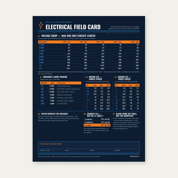
Electrical Reference Card
One page. Voltage drop lengths, breaker and wire pairing, motor FLC.
$3.99
BuyEverything electricians and industrial tradespeople need to size single-phase and three-phase transformers, calculate kVA from any load, and meet NEC 450.3 overcurrent and grounding requirements.
Transformer kVA sizing starts with coincident load demand — not nameplate HP alone. Primary and secondary voltage, impedance (%Z), harmonic content, and motor inrush all affect the correct unit selection.
Use the Transformer Sizing Calculator for instant kVA and overcurrent sizing, or work through the full guide below.

A transformer transfers electrical energy between two circuits through electromagnetic induction, with no direct electrical connection between them. The primary winding receives input voltage and current. An alternating magnetic flux is established in the core material (silicon steel laminations in dry-type units) that links the primary to the secondary winding. That changing flux induces a voltage in the secondary winding proportional to the number of turns.
The fundamental relationship is the turns ratio:
V1 / V2 = N1 / N2
Where V1 is primary voltage, V2 is secondary voltage, N1 is the number of primary turns, and N2 is the number of secondary turns. A transformer with 4:1 turns ratio steps voltage down by a factor of four: 480V primary produces 120V secondary. The same ratio inverts for current, because power is conserved across an ideal transformer:
V1 × I1 = V2 × I2 (ignoring losses)
If the secondary voltage is one-quarter of the primary, the secondary current is four times the primary current. A 480V primary drawing 10A delivers 120V secondary at up to 40A — the kVA is identical on both sides, less only the transformer's real losses (typically 1–3% efficiency loss in modern dry-type units). This inverse relationship between voltage and current is what makes transformer-based distribution systems efficient: power is transmitted at high voltage and low current to minimize I²R losses in conductors, then stepped down to utilization voltage close to the load.
Transformers only work on alternating current. DC cannot establish the changing magnetic flux required for induction. This is why AC distribution systems were adopted over DC in the late 1800s — AC can be stepped up and down efficiently; DC cannot.
For a single-phase load where current and voltage are known:
kVA = (V × I) / 1,000
For a single-phase load where watts and power factor are known:
kVA = kW / PF
Example: a single-phase 240V load drawing 45 amps at 0.85 power factor:
kVA = (240 × 45) / 1,000 = 10.8 kVA
Real power: kW = 10.8 × 0.85 = 9.18 kW
The transformer must be sized for the kVA, not the kW. The conductors and core of the transformer handle the full apparent power regardless of power factor. Select the next standard kVA size above the calculated load — in this case, a 15 kVA transformer.
For a three-phase balanced load where line voltage and line current are known:
kVA = (√3 × VL × IL) / 1,000
For a three-phase load where total watts and power factor are known:
kVA = kW / PF
Example: a 480V three-phase system serving 55A of balanced three-phase load at 0.88 power factor:
kVA = (1.732 × 480 × 55) / 1,000 = (1.732 × 26,400) / 1,000 = 45.7 kVA
Select the next standard size: a 50 kVA three-phase transformer. At 50 kVA on 480V secondary, the full-load secondary current is 50,000 / (1.732 × 480) = 60.1A — a 60A disconnect and 60A primary breaker establish the overcurrent protection limits per NEC 450.3(B).
When a transformer serves multiple loads, sum all load kVA values after applying appropriate demand factors. Not all loads operate simultaneously at full capacity. A machine shop transformer serving a 30A lathe, a 20A drill press, and four 15A receptacle circuits does not need to be sized for all loads at full draw simultaneously if they are operated one at a time. NEC Article 220 provides demand factors by load category, but for industrial facilities with unpredictable load combinations, engineering judgment — or a demand measurement per NEC 220.87 — determines the realistic coincident load.
Motor loads require special attention. Each motor's contribution to transformer kVA is based on its actual input kVA (HP × 746 / [efficiency × PF × 1,000]), not its nameplate HP alone. At startup, motors draw locked-rotor current (typically 6–8× FLA), which creates a brief but significant kVA demand spike. The transformer must handle this transient without excessive voltage sag — more on this in the sizing mistakes section.
Dry-type transformers use air as the cooling medium. The windings are insulated with varnish, epoxy, or cast resin and cooled by natural convection or forced air (fans). NEMA insulation classes define the maximum winding temperature: Class A (105°C), Class B (130°C), Class F (155°C), and Class H (180°C). Most modern dry-type distribution transformers are Class H or use 220°C-rated polyimide film insulation for additional thermal margin.
Dry-type transformers are the standard choice for commercial buildings, schools, hospitals, and light industrial facilities. Key advantages: no oil means no fire hazard from liquid spills, no requirement for a transformer vault or containment basin, and installation anywhere in a building without special drainage provisions. They are available from small control transformer sizes (25 VA) through approximately 2,500 kVA for three-phase units. Above that rating, liquid-filled units become more economical.
NEC 450.21 governs dry-type transformer installation. Transformers rated 112.5 kVA or less may be installed in occupied rooms if they are installed in a listed transformer enclosure or separated from combustible materials by a minimum of 12 inches. Transformers rated over 112.5 kVA must be installed in a transformer room with a fire resistance rating of at least one hour, or in a vault, or in an outdoor location. This is a critical code consideration for sizing — choosing a 112.5 kVA unit may allow flexible placement options where a 150 kVA unit requires a dedicated transformer room.
Liquid-filled transformers use oil (mineral oil or bio-based synthetic) or silicone fluid as both the insulating medium and the cooling fluid. The liquid has far higher heat capacity than air, enabling much more efficient heat removal and allowing significantly higher kVA ratings in a smaller physical envelope than dry-type units. Liquid-filled units are the standard for utility distribution (pole-mounted distribution transformers, substation transformers) and for large industrial loads above 2,500 kVA.
The requirement for liquid containment, fire suppression considerations, and vault or outdoor installation with spill containment makes liquid-filled units impractical for most commercial interior installations. Where they appear inside buildings, NEC 450.26 and 450.27 require transformer vaults with specific construction, drainage, and ventilation requirements. For most tradespeople working in commercial or industrial facilities, liquid-filled units are encountered at the utility service point — the padmount or pole transformer on the utility side of the meter — while everything inside the building is dry-type.
Askarel (PCB-containing fluid) transformers are no longer manufactured and the fluid is classified as a hazardous substance. If encountered in an existing installation, their replacement or proper disposal is a regulatory matter, not a simple re-energization.
Transformers are manufactured in standard kVA ratings per ANSI/IEEE C57.12.91 and related standards. These are the available sizes from stock; custom ratings are available but cost significantly more and have longer lead times. Always select the next standard size above your calculated demand.
0.05, 0.1, 0.15, 0.25, 0.5, 0.75, 1, 1.5, 2, 3, 5, 7.5, 10, 15, 25, 37.5, 50, 75, 100, 167, 250, 333, 500 kVA
The jump from 100 to 167 kVA is not a typo — 167 kVA is the standard commercial single-phase size between 100 and 250 kVA, derived from the three-phase 500 kVA size divided by three phases. Single-phase units above 167 kVA are uncommon in distribution practice; three-phase units are typically used for larger loads even when the load itself is single-phase, by using two phases of a three-phase transformer bank.
3, 6, 9, 15, 30, 45, 75, 112.5, 150, 225, 300, 500, 750, 1000, 1500, 2000, 2500 kVA
The step from 45 to 75 kVA, and from 75 to 112.5 kVA, are the most common choices in light commercial and small industrial installations. A 112.5 kVA limit also corresponds to the NEC 450.21 threshold for installation requirements, making it a frequently chosen maximum for building interior installations without a transformer room.
Calculate total coincident load in kVA. Add the growth reserve (see NEC 220.87 section below). Round up to the next standard kVA size. Do not size a transformer at exactly 100% of calculated demand — the transformer will run at or near full-rated temperature continuously, which shortens insulation life and leaves no capacity for load growth or demand spikes from motor starting. A common design target is 70–80% loading at projected peak demand, which provides thermal margin and growth headroom simultaneously.
Example: calculated coincident load of 38.5 kVA, three-phase 480V to 120/208V. Next standard size above 38.5 is 45 kVA. At 38.5 / 45 = 85.6% loading — within acceptable range. If future growth of 20% is expected: 38.5 × 1.20 = 46.2 kVA, which pushes past 45 kVA and requires selecting 75 kVA. The 75 kVA unit would operate at 46.2 / 75 = 61.6% initial loading — excellent thermal margin with room for growth.
A distribution transformer's nameplate specifies both primary and secondary voltage — and these combinations are not arbitrary. Standard utility voltages, building distribution voltages, and utilization voltages have evolved to a limited set of combinations that cover nearly all applications.
The residential and small commercial standard in North America. A single-phase transformer with a center-tapped 240V secondary provides 120V from either half and 240V across the full secondary. Most residential services are derived from a 120/240V single-phase transformer on a utility pole or in a padmount unit. Primary voltage is typically 7,200V, 12,470V, or 14,400V from the utility distribution feeder; the secondary is always 120/240V center-tapped.
The standard commercial building distribution voltage. Three-phase transformers with a 120/208V Wye secondary serve offices, retail, and light commercial occupancies. Primary is typically 480V (from a medium-voltage service step-down through a utility pad transformer to 480V, then through a building distribution transformer to 120/208V) or directly from a 2,400V, 4,160V, or 12,470V utility primary. The 120/208V secondary provides both three-phase 208V for commercial HVAC and kitchen equipment, and 120V single-phase for receptacles and lighting.
Common in light industrial facilities and older commercial installations. A 240V delta secondary provides three-phase power for motors and equipment without a neutral. The four-wire version (high-leg delta with a center-tap on one winding) provides 120V from two legs for lighting and receptacles, with the caution that the third leg (high leg or "stinger") reads approximately 208V to the center-tap neutral and cannot serve 120V loads. NEC 408.3(F) requires the high leg to be identified with orange color marking at all panelboards.
The dominant industrial distribution voltage in the United States. Virtually all large motors, HVAC compressors, and production equipment above approximately 5 HP are rated for 480V. Three-phase 480V distribution minimizes conductor sizes for high-current motor loads. The Wye version (480Y/277V) provides 277V phase-to-neutral for direct-wired industrial and commercial lighting, eliminating step-down transformers for that portion of the load. The delta version provides only 480V between phases with no neutral.
| Application | Primary Voltage | Secondary Voltage | Phase |
|---|---|---|---|
| Commercial building step-down | 480V delta | 120/208V Wye | Three-phase |
| Industrial lighting/control step-down | 480V | 120/240V | Single-phase |
| Industrial motor feed | 12,470V (utility) | 480Y/277V | Three-phase |
| Residential service | 7,200–14,400V (utility) | 120/240V center-tap | Single-phase |
| MV industrial to 480V | 4,160V or 13,800V | 480V delta or Wye | Three-phase |
| Control circuit step-down | 480V or 240V | 120V | Single-phase |
When specifying a transformer, both primary and secondary voltages must match the actual system voltages at that point in the distribution — not a generic "480V to 120V." A 480V delta primary and a 480Y/277V primary are different configurations even though both read 480V line-to-line. Confirm the transformer's primary winding configuration matches the source system's configuration.
NEC Section 220.87 provides a method for determining the existing load on a service or feeder by measuring peak demand over a 30-day period rather than calculating it from individual circuits. The measured demand, adjusted for any known load additions, becomes the basis for determining remaining capacity. This is particularly useful when evaluating whether an existing transformer has capacity for additional loads before specifying a replacement.
For new transformer sizing, the standard engineering practice is to add a growth factor to the initial calculated demand. The appropriate growth factor depends on the facility type and planned horizon:
A conservative approach is to size the transformer for 125% of the initial calculated coincident demand — a 25% growth reserve that typically accommodates 5–10 years of normal load growth. More aggressive growth expectations in manufacturing environments, data centers, or facilities with planned equipment additions should use a higher multiplier. Some design standards specify sizing to 80% of transformer rated kVA at initial full load, which inherently provides a 25% growth reserve above the transformer's continuous rating.
The cost difference between adjacent standard kVA sizes is often modest compared to the cost of replacing or paralleling a transformer that has been outgrown. A 75 kVA unit costs perhaps 30–40% more than a 45 kVA unit; the labor to install either is similar; the physical footprint difference is moderate. The cost of a premature transformer replacement — engineer time, equipment cost, installation labor, panel modifications, and production downtime — is orders of magnitude higher. When in doubt on a facility that will grow, select the next larger standard size.
Transformer impedance (%Z) is the percentage of rated voltage required at the primary to drive rated current through a short-circuited secondary. A 5% impedance transformer requires 5% of rated primary voltage — 24V on a 480V primary — to push full rated current through a bolted short at the secondary terminals. It expresses the transformer's internal resistance and leakage reactance as a fraction of its rated impedance.
Standard dry-type distribution transformers are typically available at 4%, 5%, or 6% impedance. Some manufacturers offer 2–3% impedance for applications requiring tighter voltage regulation. The choice of %Z is a design decision that involves tradeoffs between fault current, voltage regulation, and cost.
The maximum available fault current at the transformer secondary is approximately:
Single-phase: Isc = IFLA / (%Z / 100)
Three-phase: Isc = IFLA / (%Z / 100)
Where IFLA is the transformer's full-load secondary current at rated kVA.
Example: 75 kVA three-phase transformer, 208V secondary, 5% impedance.
Secondary FLA = 75,000 / (1.732 × 208) = 75,000 / 360.3 = 208.2A
Isc = 208.2 / 0.05 = 4,164A available fault current
Every overcurrent device, busbar, and switchboard downstream of that transformer must have an interrupting rating sufficient for 4,164A. This calculation assumes an infinite bus (zero impedance) on the primary side, which overstates fault current slightly but is the conservative approach for device ratings. The actual available fault current is reduced by the primary system impedance, conductor impedance, and the path length to the fault location.
Lower %Z means higher available fault current — a 2% impedance transformer at the same 75 kVA rating would produce 10,410A of available fault current, which may exceed the interrupting rating of standard 22 kA molded case breakers. Higher %Z limits fault current but increases voltage drop under load.
Percent impedance is the primary determinant of voltage regulation — how much the secondary voltage drops between no load and full load. Higher %Z = worse voltage regulation (more voltage drop at full load). A 5% impedance transformer delivering rated current will experience approximately 4–5% voltage drop from no-load to full-load secondary voltage. A 2% impedance unit drops approximately 1.5–2%.
For sensitive electronic loads (VFDs, PLCs, medical equipment, precision measurement instruments), tight voltage regulation is important. Specifying lower %Z or installing the transformer closer to the load (shorter secondary conductors) improves delivered voltage under load. For motor loads with variable demand, slightly higher %Z (5–6%) naturally limits inrush impact on the system because the transformer's own impedance absorbs some of the inrush voltage transient — the tradeoff is higher steady-state voltage drop at full load.
NEC Section 450.3 governs transformer overcurrent protection and is one of the more nuanced sections of the code because the rules differ depending on whether protection is provided on the primary side only, or on both primary and secondary. Table 450.3(B) covers transformers rated 600V or less on both sides (the most common case for commercial and industrial distribution transformers).
Primary protection only (no secondary OCPD):
If the primary current is 9 amperes or more: maximum OCPD = 125% of primary full-load current (round up to next standard size if 125% doesn't correspond to a standard rating).
If the primary current is less than 9A but more than 2A: maximum OCPD = 167% of primary FLA.
If the primary current is 2A or less: maximum OCPD = 300% of primary FLA.
Both primary and secondary protection:
Primary OCPD: maximum 250% of primary FLA.
Secondary OCPD: maximum 125% of secondary FLA.
When both primary and secondary protection are provided, the higher allowable primary OCPD (250%) reduces nuisance tripping on inrush and allows larger feeders to feed the transformer without requiring an oversized breaker at the panel.
Practical example: 45 kVA three-phase transformer, 480V primary, 5% impedance.
Primary FLA = 45,000 / (1.732 × 480) = 54.1A
Primary-only protection: 54.1 × 1.25 = 67.6A → next standard size = 70A breaker or fuse
With secondary protection: primary up to 54.1 × 2.50 = 135.2A → 150A breaker acceptable
Secondary FLA at 208V: 45,000 / (1.732 × 208) = 124.9A → secondary OCPD at 125% = 156.1A → 175A breaker
NEC 450.9 requires adequate ventilation for transformer installations. Heat generated by transformer losses (typically 1–3% of rated kVA) must be dissipated without allowing the winding temperature to exceed the insulation class rating. The NEC requires that transformers be installed so that adequate ventilation is provided and maintained.
NEMA and manufacturer installation instructions specify minimum clearances — typically 12 inches on the sides and top for natural convection-cooled units, with greater clearances required for transformers with integral cooling fans. Indoor transformer rooms used for transformers over 112.5 kVA must have ventilation openings calculated to remove heat continuously: a common sizing rule is 1 square foot of ventilation opening per 50 kVA of transformer capacity for natural convection. Forced ventilation systems reduce the required opening area but must be interlocked to shut down the transformer if ventilation fails.
Do not install dry-type transformers in enclosures that trap heat — electrical rooms with no ventilation, false ceilings with no air circulation, or utility closets sized to the transformer with no airflow path. Thermal overloads on dry-type transformers are irreversible — once the insulation exceeds its rated temperature class repeatedly, the winding insulation degrades, its dielectric strength decreases, and the transformer's service life is permanently shortened.
A transformer secondary is a separately derived system when there is no direct electrical connection between the source (primary circuit) and the output (secondary circuit). Most isolation transformers, including standard 480V-to-120/208V building distribution transformers, create separately derived systems. The grounded conductor (neutral) and equipment grounding of the separately derived system must be established at the transformer in compliance with NEC 250.30.
The key requirements under NEC 250.30(A):
System bonding jumper: A bonding jumper must connect the grounded conductor (X0 neutral terminal) to the transformer enclosure and to the equipment grounding conductor at the transformer. This can be done inside the transformer at the secondary terminals. This is the only point in the separately derived system where the neutral is bonded to the equipment grounding path — bonding again downstream (at a sub-panel, for example) creates parallel neutral-to-ground current paths and is a code violation.
Grounding electrode conductor: A grounding electrode conductor (GEC) must connect from the X0 terminal (or the system bonding jumper point) to a grounding electrode system at or near the transformer. If the building grounding electrode system is nearby, it can be used. If not, an electrode must be established per NEC 250.50. The GEC must be sized per NEC Table 250.102(C)(1) based on the largest ungrounded secondary conductor.
Failure to establish proper separately derived system grounding is one of the most common errors on transformer installations. It results in floating secondary neutrals, unreliable ground fault detection, and potential shock hazards at secondary equipment.
The designation "step-up" or "step-down" describes the voltage change from primary to secondary — but it is a label applied to the use case, not an inherent property of the transformer. Any two-winding transformer can be operated in either direction; a step-down transformer used with the low-voltage winding as the primary becomes a step-up transformer. The only constraints are the voltage ratings and current ratings of each winding, which must not be exceeded regardless of direction.
Step-down transformers are far more common in building distribution: utility voltage is stepped down to utilization voltage at the service point, then distribution transformers step down again from 480V to 120/208V within the building. Step-up transformers appear in specific applications:
Variable frequency drives (VFDs) used with 230V motors on 460V distribution sometimes include step-down transformers. More commonly, step-up is used to feed 480V equipment from a 208V source — a situation encountered when a piece of industrial equipment designed for 480V is installed in a commercial building with only 208V available. A 208V-to-480V step-up transformer provides the 480V supply; the transformer kVA must match the equipment's full load draw.
Arc welding and plasma cutting equipment sometimes uses step-down transformers for voltage matching. High-frequency signal transformers (isolation transformers for instrumentation, audio step-up transformers for microphone levels) operate on the same electromagnetic induction principles as power transformers but at different frequency and impedance ranges.
Control transformers are small single-phase dry-type isolation transformers, typically with a 480V primary and 120V secondary, used to power control circuits: motor starters, relay coils, pilot lights, PLC power supplies, and operator interface terminals. They are sized in VA (volt-amperes) rather than kVA because most are well under 1 kVA.
Standard control transformer VA ratings: 25, 50, 75, 100, 150, 200, 250, 300, 500, 750, 1,000 VA. Common physical form: potted or open style in DIN rail or panel-mount enclosures. Brands: Hammond Manufacturing, Acme (now part of ABB), Square D Class 9070 series, Marcus Transformers.
Control transformer sizing is more involved than distribution transformer sizing because control loads include solenoid coils, motor starter coils, and contactor coils that draw significantly higher inrush current during energization than their steady-state running current. The standard method:
Step 1 — Inrush load: Sum the inrush VA of all loads that can energize simultaneously. Solenoid valve coils draw 6–10× their sealed (running) VA during the first half-cycle. Motor starter coils draw approximately 6× their sealed VA on energization. Pilot lights draw essentially constant VA.
Step 2 — Running load: Sum the steady-state (sealed) VA of all loads that can be energized simultaneously.
Step 3 — Select transformer VA: The transformer must handle the inrush VA without voltage sag that prevents coils from sealing. As a practical guideline, the transformer should be sized so that the inrush VA does not exceed 200% of the transformer's VA rating — meaning the inrush load should not exceed twice the transformer rating during the starting transient. Running VA must not exceed 80% of the transformer rating for continuous duty.
Example: A control circuit energizes two motor starter coils simultaneously (6 VA sealed, 36 VA inrush each) and keeps two pilot lights on continuously (4 VA each) plus a PLC power supply (25 VA constant).
Inrush VA: (36 + 36) + (4 + 4) + 25 = 105 VA inrush peak
Running VA: (6 + 6) + (4 + 4) + 25 = 45 VA running
Inrush rule: transformer rating ≥ 105 / 2.0 = 52.5 VA → select 75 VA (next standard size)
Running check: 45 / 75 = 60% — well within 80% limit ✓
NEC 430.72 covers control circuit transformer overcurrent protection. Primary-only protection at 500% of primary FLA is permitted for control transformers with secondary conductors protected by the secondary current limitation inherent in a 2-ampere or less secondary overcurrent device.
The most common and consequential sizing mistake on industrial installations is failing to account for motor starting inrush current and its effect on transformer voltage. When a large motor starts across-the-line, it draws locked-rotor current (6–8× FLA) for 2–5 seconds. This inrush demands a large kVA surge from the transformer. If the transformer is sized to handle only steady-state operating kVA, the inrush can cause secondary voltage to sag by 10–20% during starting, which is enough to prevent the motor from developing adequate starting torque, trip protective relays, and disturb other loads on the same transformer secondary.
The transformer impedance (%Z) determines how much voltage sags during motor starting. Voltage sag at the transformer secondary during motor start is approximately:
%V sag ≈ Istart / Isc × 100
Where Istart is the motor locked-rotor current and Isc is the transformer available fault current (FLA / %Z).
For a 45 kVA transformer with 5% impedance serving a 208V secondary, Isc = 208.2 / 0.05 = 4,164A. Starting a 15 HP motor with 200% nameplate FLA of 42A → LRA ≈ 42 × 6 = 252A. Voltage sag = 252 / 4,164 = 6.0% — acceptable. Starting a 50 HP motor (FLA 143A) on the same transformer: LRA = 143 × 6 = 858A. Voltage sag = 858 / 4,164 = 20.6% — severe, will likely prevent motor starting and disturb all other loads on the transformer. The transformer is undersized for this motor, regardless of steady-state kVA.
When large motor starting is a design requirement, consider: a larger transformer with lower %Z (more fault current → smaller voltage sag percentage), a solid-state soft starter to limit inrush to 2–3× FLA, or a variable frequency drive (which limits inrush to approximately 100–150% of motor FLA during acceleration).
Variable frequency drives, switched-mode power supplies (computers, UPS systems, electronic ballasts), arc welders, and induction heating equipment generate harmonic currents — current components at frequencies that are integer multiples of 60 Hz (180 Hz, 300 Hz, 420 Hz, etc., corresponding to the 3rd, 5th, 7th harmonics). Standard transformers are designed for sinusoidal 60 Hz current only. Harmonic currents cause additional eddy current and hysteresis losses in the core, and additional I²R losses in the windings, over and above the losses from the fundamental 60 Hz component. This extra heating degrades standard transformers faster than their rated life when harmonic loads are significant.
The solution is a K-factor rated transformer. K-factor is a weighting of the harmonic current spectrum that indicates the transformer's ability to handle harmonic heating:
K-1: Standard transformer, designed for sinusoidal loads only.
K-4: Suitable for moderate harmonic loads (electronic lighting ballasts, small UPS systems, some office equipment).
K-13: Suitable for heavier harmonic loads (mix of VFDs, adjustable speed drives, solid-state welders).
K-20: Suitable for severe harmonic environments (SCR drives, rectifier banks, telecommunications power supplies).
A facility where 50% or more of the transformer load is served through VFDs should specify a K-13 transformer at minimum. Installing a standard K-1 transformer in a heavily harmonic environment causes premature insulation aging, increased operating temperature, and eventual failure at a fraction of the expected service life. The incremental cost of a K-13 over a K-1 transformer is typically 15–25% — far less than a premature replacement and associated downtime costs.
Summing all connected load nameplate ratings and sizing a transformer for 100% coincident operation of all loads overestimates the required kVA in most facilities. Not all loads operate simultaneously at full rated output — machines are operated on rotating shifts, lighting is switched zone by zone, HVAC loads cycle with thermostat control. Applying appropriate demand factors from NEC Article 220 or from measured demand data (NEC 220.87 method) typically reduces the required transformer kVA by 20–40% compared to a naive nameplate-sum approach.
However, the opposite error — assuming too generous a demand factor and undersizing the transformer — is the more expensive mistake. A transformer that runs at 95% of rated kVA continuously operates near the thermal limit of its insulation class and has no growth margin. Demand factor analysis requires discipline: identify which loads are truly non-coincident (only one can run at a time), which are continuously coincident (always on together), and which are variable (HVAC, lighting). Build the demand factor analysis from actual operational knowledge of the facility, not optimistic assumptions.
One page. Voltage drop lengths, breaker and wire pairing, motor FLC.
$3.99
Buy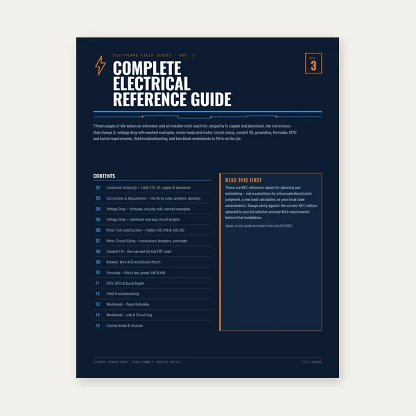
15 pages. Ampacity, corrections, voltage drop, motor circuits, conduit fill.
$12.99
Buy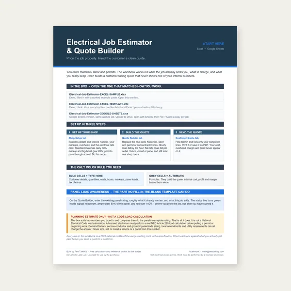
Quote electrical work and flag panel headroom before you price it.
Excel or Google Sheets. Best on a computer.
$29.00
Buy
Card, 15-page guide and the estimator workbook. All six files.
Excel or Google Sheets. Best on a computer.
$34.99
$45.98 if bought separately — save $10.99
BuyCheckout opens in a new tab.
Measure primary and secondary current, verify voltage, and confirm de-energization before transformer work

Measuring primary and secondary current on transformer circuits requires a true-RMS clamp rated for the voltage class you are working in. The Klein CL800 reads AC/DC current up to 600A with 1000V CAT IV safety rating — the right meter for verifying load balance and troubleshooting overheating on dry-type distribution transformers.
Check Price
Verifying primary and secondary voltage before energizing a transformer is non-negotiable. The Fluke 117 reads true RMS voltage with non-contact detection — confirm winding configuration, phase-to-neutral readings, and de-energization before making connections at the X0 neutral or secondary terminals.
Check Price
High-current measurement on large transformer secondaries demands a clamp with adequate jaw capacity and true-RMS accuracy on distorted waveforms. The Ideal 61-757 handles up to 600A AC/DC — useful for reading secondary current on 75 kVA and larger distribution transformers during load testing.
Check Price
Quick voltage presence verification before transformer work prevents the most avoidable shock incidents on energized switchgear and transformer rooms. The Klein NCVT-6 confirms energized conductors without contact and includes a laser distance meter for layout work around transformer installations.
Check Price
Reference breaker for secondary overcurrent protection sizing — NEC 450.3(B) governs maximum primary and secondary OCPD for transformers rated 600V or less. The Square D QO120 is the industry-standard 20A single-pole breaker used as a baseline reference when sizing secondary branch protection.
Check PriceAs an Amazon Associate, TestTalkHQ earns from qualifying purchases.
Every transformer calculation flows from the turns ratio: the ratio of primary to secondary winding turns determines both the voltage transformation and the inverse current transformation. A 4:1 turns ratio steps 480V down to 120V and simultaneously steps 10A of primary current up to 40A of secondary current — the kVA is conserved on both sides, less only the transformer's real losses. Understanding the turns ratio makes it clear why oversizing the transformer for voltage accuracy matters: the secondary voltage is determined by the ratio, and any variation in primary voltage directly affects secondary voltage by the same percentage. Tighter primary voltage regulation produces more stable secondary voltage, regardless of transformer size.
Transformer impedance (%Z) controls two competing outcomes: voltage regulation and available fault current. Lower %Z means the secondary voltage stays flatter under varying load — less voltage drop from no-load to full-load — but it also means higher available fault current at the secondary, which requires higher-rated overcurrent devices and switchgear downstream. Higher %Z limits fault current (reducing equipment interrupting rating requirements) but produces worse voltage regulation — the secondary voltage sags more as load increases. Most distribution transformers are specified at 4–6% impedance as a compromise between these competing requirements. Facilities with large motor loads that need tight voltage regulation during starting often specify lower %Z; facilities where fault current must be limited to protect low-rating switchgear specify higher %Z.
Standard dry-type transformers are rated for sinusoidal 60 Hz loads. Variable frequency drives, switching power supplies, electronic ballasts, UPS systems, and arc welders all generate harmonic currents — components at 3rd, 5th, 7th, and higher harmonics of 60 Hz — that cause additional core and winding losses beyond what a standard transformer was designed to dissipate. Installing a standard transformer on a heavily harmonic load results in overheating and shortened insulation life. K-factor rated transformers use oversize neutral conductors, reduced core flux density, and additional winding material to handle harmonic currents without excessive temperature rise. Specify K-4 for light harmonic loads, K-13 for facilities where VFDs or mixed drives represent 40%+ of the transformer load, and K-20 for severe rectifier or SCR drive environments.
A transformer secondary creates a separately derived system — a new electrical source isolated from the primary by the transformer's windings. NEC 250.30 requires that the separately derived system neutral be bonded to the transformer enclosure and equipment grounding at the transformer, and that a grounding electrode conductor connect the neutral to a grounding electrode system at or near the transformer location. This bonding and grounding must occur at one point only — the transformer. Re-bonding the neutral to ground at a downstream panelboard creates parallel current paths that cause neutral current to flow on equipment grounding conductors, producing noise in electronic systems, nuisance GFCI trips, and potential shock hazards. Separately derived system grounding is a frequent source of field errors and is worth verifying explicitly on every new transformer installation.
Start by calculating the kVA for each motor at its actual operating input power — motor HP × 746 / (efficiency × power factor × 1,000) — not from the nameplate HP alone, since that understates input kVA by the efficiency and power factor factors. For receptacle circuits, apply the NEC demand factors from Article 220 for the load type (or use measured demand if available). Sum the individual kVA values with their coincidence factors: which loads run simultaneously, which alternate? Motor inrush must also be considered separately — the largest motor's locked-rotor current imposes a transient kVA demand that can be 5–7× the motor's running kVA, and the transformer must handle this without excessive voltage sag. After summing coincident load kVA and verifying motor starting voltage drop is acceptable, add 20–25% for growth, then round up to the next standard kVA size.
Paralleling dry-type transformers is technically possible but requires that both units have identical voltage ratios, identical impedance (%Z), and identical phase displacement (both Wye or both Delta, or both Wye-to-Delta with the same phase shift). If the impedances are not matched, load does not share equally — the lower impedance unit carries a disproportionate share of the load and will overheat while the higher impedance unit is underloaded. Most manufacturers and NEC-compliant designs avoid paralleling small to medium distribution transformers because the matching requirements are difficult to meet with off-the-shelf units. The preferred alternative when capacity is insufficient is to replace the transformer with the next larger standard size. Paralleling is common practice in large utility substation applications where purpose-designed matched units are specified.
Distribution transformers are sized in kVA and designed to deliver power to load circuits — motors, lighting, receptacles, HVAC. Their secondary current capacity is the primary design parameter, and they are sized based on connected kVA load. Control transformers are sized in VA and are designed to power control circuits — relay coils, starter coils, pilot lights, PLC power supplies — which are low-power but often have high inrush-to-running ratios due to solenoid and contactor coil energization. A control transformer must be sized for the peak inrush of simultaneously energized coils, not just the steady-state running current. NEC 430.72 specifically addresses control circuit overcurrent protection requirements, including rules for control transformers integral to motor controller equipment. Control transformers are typically single-phase units rated 25 VA through 1,000 VA; distribution transformers start around 1 kVA and run to thousands of kVA.
Transformer hum is caused by magnetostriction — the silicon steel core laminations physically expand and contract at twice the supply frequency as the magnetic flux cycles (120 times per second at 60 Hz), producing a characteristic 120 Hz fundamental tone and harmonics. All energized transformers hum to some degree; the question is whether the noise level is normal for the size and load. A transformer that suddenly becomes louder than its baseline may be experiencing loose core laminations (which can be caused by sustained mechanical vibration, aging of the adhesive between laminations, or thermal cycling), or it may be operating under heavy harmonic loading, which increases core vibration. Harmonic loads from VFDs and switching power supplies cause the core to experience flux components at multiple frequencies simultaneously, producing a rougher, louder sound than the smooth 120 Hz tone of a lightly loaded transformer on sinusoidal current. A transformer that becomes noticeably louder, begins vibrating its enclosure, or produces a sound character that changes significantly from its initial energized state warrants inspection — loose laminations in severe cases can progress to core damage.