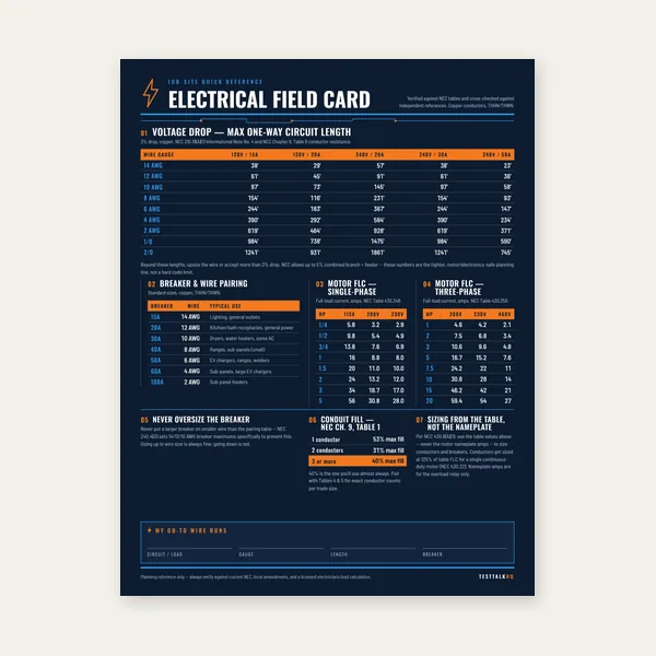
Electrical Reference Card
One page. Voltage drop lengths, breaker and wire pairing, motor FLC.
$3.99
BuyEverything electricians and industrial tradespeople need to calculate three-phase voltage, current, kVA, real power, and power factor for Wye and Delta systems.
Three-phase power runs every industrial plant, large commercial building, and utility grid. Line voltage, phase voltage, kVA, kW, and power factor are related by fixed formulas — but only when you know whether the system is Wye or Delta.
Use the Three-Phase Power Calculator for instant kVA, current, and power factor results, or work through the full guide below.

Single-phase power delivers voltage that rises and falls as a sine wave, reaching zero twice per cycle. Three-phase power consists of three separate sine waves offset from each other by 120 degrees. Because the three phases are staggered, the combined power delivery is smooth and continuous — no zero crossings in the total waveform. For motors, this is the fundamental reason three-phase is used: a three-phase induction motor develops a rotating magnetic field naturally from the three offset currents and is self-starting, whereas a single-phase motor requires a starting capacitor or auxiliary winding to develop starting torque.
Beyond motor performance, three-phase is more efficient to transmit and distribute. Three wires carrying three-phase power deliver three times the power of a single-phase two-wire circuit at the same voltage and current. Expressed differently, for a given amount of power delivered to a load, three-phase uses about 75% of the copper that single-phase requires. This efficiency advantage is why all utility transmission infrastructure, all large commercial facilities, and all industrial plants run on three-phase. Single-phase circuits within those buildings are derived from the three-phase system for lighting, receptacles, and small appliance loads.
A second practical advantage is heat and vibration in large motors. Three-phase motors run cooler and more smoothly than single-phase motors at equivalent HP ratings because the power pulses overlap continuously rather than pulsing twice per cycle. A 50 HP three-phase motor is a routine piece of shop equipment. A 50 HP single-phase motor would require capacitors the size of trash cans and would still produce objectionable vibration.
Every three-phase system — generators, transformers, and motors — connects its three windings in one of two configurations: Wye or Delta. The configuration determines the relationship between line voltage (what you measure between phases) and phase voltage (what appears across each individual winding), and between line current and phase current.
In a Wye connection, one end of each winding is tied together at a common point called the neutral. The other end of each winding connects to a line terminal (A, B, or C). Drawn out, the arrangement looks like the letter Y — three arms radiating from a center point, which is why it is also called a star connection.
The voltage relationship in a Wye system follows directly from the geometry of three vectors separated by 120°:
Line Voltage = √3 × Phase Voltage
Phase Voltage = Line Voltage / √3 = Line Voltage × 0.5774
In a 480V Wye system, the phase voltage (from any line terminal to the neutral) is 480 / 1.732 = 277V. This is exactly why 480Y/277V is the standard commercial building distribution voltage in the United States — 277V is usable for direct-wired fluorescent and LED lighting, and 480V is available for three-phase motor loads. The neutral wire in a Wye system carries unbalance current (the difference between phases when loads are not equal) and is required for any load that uses the phase-to-neutral voltage.
For current in a Wye system:
Line Current = Phase Current
Each line conductor carries the same current that flows through the winding connected to it. There is no multiplication factor.
In a Delta connection, the three windings are connected end-to-end, forming a closed triangle (the Greek letter delta, Δ). Each winding connects directly between two line terminals with no neutral point.
In a Delta system, the voltage relationship is:
Line Voltage = Phase Voltage
The voltage across each winding is identical to the line-to-line voltage. A 480V delta system has 480V across each winding. There is no factor of √3 in the voltage relationship.
The current relationship reverses — here √3 appears in the current equation:
Line Current = √3 × Phase Current
Phase Current = Line Current / √3
In a delta system, each line current is the vector sum of the currents flowing through two windings simultaneously. This is why delta-wound equipment (certain motor windings, transformer primaries) must be current-rated at 1/√3 of the line current it will carry, not the full line current.
A variation common in older US commercial installations is the 240V four-wire delta system with a center tap on one winding. This center tap provides a neutral conductor and creates 120V to neutral on two of the three phases (A and C). The third phase (B phase, the "high leg" or "wild leg") measures approximately 208V to the neutral — not 120V. This is because the B phase winding does not have its midpoint grounded; it sits at the apex of a triangle while the neutral grounds the base midpoint.
Specifically: in a 240V delta with a grounded center tap on one winding, the high leg voltage to neutral = √3/2 × 240V = 0.866 × 240V ≈ 208V. NEC 408.3(F) requires the high leg to be identified with orange color coding at all panelboards, and the high leg must occupy the B (center) position in a panel. Connecting 120V equipment to the high leg destroys the equipment — 208V fed to a 120V device is not a marginal overvoltage; it is an immediate failure.
Understanding the √3 relationship is not academic; it is the source of the most common measurement errors when working on three-phase equipment. When you put a voltmeter across two line terminals on a Wye-wound transformer secondary, you read line voltage. When you put the same meter from any line terminal to neutral, you read phase voltage. These are two different voltages on the same system and they differ by a factor of 1.732.
Common Wye system voltages in the US:
| System | Line Voltage (L-L) | Phase Voltage (L-N) | Typical Use |
|---|---|---|---|
| 120/208V Wye | 208V | 120V | Commercial buildings, offices, light commercial |
| 277/480V Wye | 480V | 277V | Industrial plants, large commercial, HVAC |
| 347/600V Wye | 600V | 347V | Canada standard, some US heavy industrial |
The 120/208V system is the most common in commercial construction. A tenant's panel in an office building will have 208V between phases (for three-phase equipment and some single-phase 208V loads) and 120V from any phase to neutral (for receptacles, lighting, and standard office equipment). A 120V device plugged into a 120V receptacle in that building is running on phase voltage, not line voltage.
The 277/480V system dominates industrial facilities and large commercial buildings. Lighting circuits in warehouses, factories, and big-box retail are typically run at 277V — the phase voltage of the 480V Wye system — because it reduces conductor current for the same wattage compared to 120V lighting. Large motors run at 480V line voltage. Small motors and controls are often stepped down to 120V via control transformers.
In a delta system, there is no L-N voltage available (there is no neutral) unless a center tap is provided on one winding as in the high-leg delta arrangement described above. A pure 480V delta system presents only 480V between any two terminals — no 277V phase voltage is accessible.
Three-phase power calculations use three related quantities: real power (P), apparent power (S), and reactive power (Q). Each is measured in different units and describes a different aspect of what the circuit is doing.
Apparent Power (kVA):
S = √3 × VL × IL
Apparent power is the total power the conductors and equipment must handle, regardless of how much useful work is being done. It is what the utility measures for billing purposes (before any power factor adjustment) and what determines conductor and transformer sizing. A transformer rated 75 kVA can deliver 75 kVA of apparent power regardless of the load's power factor.
Real Power (kW):
P = √3 × VL × IL × PF
Real power (also called active power or true power) is the power actually converted to useful work — mechanical rotation, heat, light. It is measured in watts or kilowatts. Only real power does work. A motor that draws 100 kVA at 0.85 power factor delivers 85 kW of real power to the load; 15 kVA is reactive and returns to the source each half-cycle without doing net work.
Reactive Power (kVAR):
Q = √3 × VL × IL × sin(θ)
Reactive power is the power oscillating back and forth between the source and the magnetic or electric fields of inductive or capacitive loads. Motors and transformers store energy in their magnetic fields each half-cycle and return it the next. This exchange requires current flow through the conductors and creates losses in resistance, even though no net work is done. Reactive power is measured in kVAR (kilovolt-ampere reactive).
The three power quantities form a right triangle:
S² = P² + Q²
Apparent power (kVA) is the hypotenuse. Real power (kW) is the horizontal leg. Reactive power (kVAR) is the vertical leg. The angle between the kVA hypotenuse and the kW leg is the power factor angle (θ), and its cosine is the power factor:
PF = cos(θ) = P / S = kW / kVA
Rearranging the power triangle gives the remaining useful relationships:
Q = √(S² − P²) — reactive power from apparent and real power
P = S × PF — real power from apparent power and PF
S = P / PF — apparent power from real power and PF
A 480V three-phase industrial panel feeds a combination of motor and resistive loads. The measured line current is 120A and the power factor is 0.88 lagging.
Apparent power: S = √3 × 480 × 120 = 1.732 × 480 × 120 = 99.8 kVA
Real power: P = 99.8 × 0.88 = 87.8 kW
Reactive power: Q = √(99.8² − 87.8²) = √(9,960 − 7,709) = √2,251 = 47.4 kVAR
The panel is doing 87.8 kW of useful work but drawing current equivalent to 99.8 kVA. The conductors, breakers, and transformer must handle the full 99.8 kVA — but the utility bills only for the 87.8 kW of real energy consumed (though they may add a power factor penalty charge for the reactive component).
Power factor is the ratio of real power to apparent power. A power factor of 1.0 (unity) means the voltage and current waveforms are exactly in phase — peaks and zero crossings align perfectly. Every amp of current flowing in the circuit is doing useful work. This is the case for purely resistive loads: electric heaters, incandescent lighting, resistance welders running at DC.
In an inductive load (motor, transformer, reactor), current lags voltage. The current peak occurs after the voltage peak because energy is first stored in the magnetic field before being released. This lag — measured in degrees as the phase angle θ — means that when voltage is at its peak, current has not yet reached its peak. The product of instantaneous voltage and instantaneous current is therefore less than it would be if they were in phase. PF = cos(θ) quantifies this reduction: a 30° lag gives PF = cos(30°) = 0.866, meaning only 86.6% of the apparent power is doing real work.
Poor power factor increases the current the system must carry for a given amount of real work. A 100 kW load at unity power factor draws 100 kW / (√3 × 480V) = 120.3A at 480V. The same 100 kW load at 0.75 PF draws 100 / (√3 × 480 × 0.75) = 160.4A — 33% more current for the same useful output. That additional current flows through every conductor, breaker, and transformer between the load and the utility meter. It causes additional I²R heating losses in all conductors. It requires larger conductors, larger transformers, and larger switchgear to handle the same real-work load.
Utilities measure this through demand billing. Most industrial utility rates include a demand charge based on peak kVA (or peak kW with a power factor adjustment). A facility drawing 1,000 kW at 0.70 PF is pulling 1,429 kVA of apparent power. A facility drawing the same 1,000 kW at 0.95 PF pulls 1,053 kVA. Utilities charge for the infrastructure capacity the customer requires, which scales with kVA — the lower-PF facility pays significantly more per kWh of useful energy consumed. Many utilities also apply direct power factor surcharges when average PF falls below 0.85 or 0.90.
Power factor correction is accomplished by adding capacitor banks in parallel with inductive loads. Capacitors produce leading reactive power (kVAR) that cancels the lagging kVAR of motors and transformers, reducing the net reactive demand the utility sees. Properly sized capacitor banks bring the facility PF to 0.95 or above, eliminating demand penalties and reducing current on all upstream conductors.
| Load Type | Typical PF at Full Load | Typical PF at 50% Load |
|---|---|---|
| Three-phase induction motor (large) | 0.88–0.93 | 0.72–0.82 |
| Three-phase induction motor (small) | 0.80–0.88 | 0.60–0.75 |
| Electric resistance heater | 1.00 | 1.00 |
| Fluorescent/LED lighting (ballasted) | 0.85–0.95 | 0.85–0.95 |
| MIG/TIG welding machine | 0.70–0.85 | 0.50–0.70 |
| Variable frequency drive (VFD) | 0.95–0.98 (input) | 0.93–0.97 |
| Arc furnace | 0.65–0.80 | — |
| Typical industrial facility (mixed) | 0.75–0.88 | — |
Note that lightly loaded motors have significantly worse power factor than fully loaded motors. Running a 50 HP motor at 15 HP of actual load is common in shops with intermittent duty equipment, and the PF drop from 0.88 to 0.65 or lower means the circuit is carrying substantial reactive current for minimal useful output. Right-sizing motors for their actual loads improves both PF and efficiency simultaneously.
A balanced three-phase system has equal impedances (loads) on all three phases, which produces equal currents on all three lines and zero net neutral current in a Wye system. The power calculations above assume a balanced system. Unbalanced loads — different amounts of single-phase load connected between each line and neutral — create unequal phase currents, non-zero neutral current, and voltage unbalance across the three phases.
Voltage unbalance is expressed as a percentage per NEMA MG 1:
% Voltage Unbalance = (Max deviation from average / Average line voltage) × 100
If a 208V system measures 206V on phase A-B, 210V on B-C, and 204V on A-C, the average is 206.7V. The maximum deviation is 210 − 206.7 = 3.3V. Percent unbalance = (3.3 / 206.7) × 100 = 1.6%.
NEMA MG 1 recommends that motors not be operated with voltage unbalance exceeding 1%. Above 1% unbalance, motors must be derated — a motor operated at 5% voltage unbalance must be derated to approximately 75% of its nameplate HP to avoid excessive heating. The temperature rise in the motor windings increases approximately as the square of the percent voltage unbalance: 3.5% unbalance can increase winding temperature rise by 25% or more, significantly shortening insulation life.
Unbalance in the distribution system typically traces to unequal single-phase loads connected to the three phases. A building with heavily loaded A-N and B-N circuits and lightly loaded C-N circuits will show current and voltage unbalance. Correcting it requires redistributing single-phase loads more evenly across the three phases — a task that requires measuring current on each phase separately and re-connecting loads at the panelboard.
Given the three-phase kVA of a load and the system voltage, the line current is:
IL = (kVA × 1,000) / (√3 × VL)
For a 75 kVA transformer secondary at 480V:
I = 75,000 / (1.732 × 480) = 75,000 / 831.4 = 90.2A
The conductors and overcurrent protection must handle this current. For continuous loads (operating for 3 hours or more), NEC 210.19 and 215.2 require conductors rated at 125% of the continuous load. The overcurrent device must also be rated at a minimum of 125% of the continuous load per NEC 210.20(A): 90.2A × 1.25 = 112.8A, round up to the next standard size: 125A breaker, with conductors rated for at least 112.8A at the termination temperature.
For three-phase motors, the full-load ampere (FLA) rating from the motor nameplate is the correct starting point for circuit sizing — not a calculated value from HP and assumed efficiency. NEC Table 430.250 provides FLA values for standard three-phase motors that the code uses for circuit sizing purposes even if the nameplate FLA differs slightly. Use the nameplate FLA for all actual operating calculations (heat rise, voltage drop); use NEC Table 430.250 values only when the nameplate is not available or for initial design estimates.
Motor branch circuit conductor sizing per NEC 430.22: conductors must be rated at minimum 125% of motor FLA.
Motor OCPD sizing per NEC 430.52: for a Design B squirrel cage motor with an inverse time breaker, maximum OCPD = 250% of motor FLA (rounded up to next standard size).
Example: 25 HP, 480V, three-phase motor. NEC Table 430.250 FLA = 34A.
Conductor ampacity required: 34A × 1.25 = 42.5A → 8 AWG copper at 75°C (50A rated).
Maximum breaker size: 34A × 2.50 = 85A → next standard size up to 90A breaker (if 85A doesn't trip on starting; if it does, the code allows going to 400% for certain conditions before an inverse time breaker must be used — see NEC 430.52(C)(1) Exception).
When real power (kW) is known but PF must be accounted for:
IL = (kW × 1,000) / (√3 × VL × PF)
A 60 kW combined load on 480V three-phase at 0.85 PF:
I = 60,000 / (1.732 × 480 × 0.85) = 60,000 / 707.1 = 84.9A
Ignoring PF and calculating from kW at unity PF would give 60,000 / 831.4 = 72.1A — 15% undersized. On a large distribution board this error translates to undersized conductors and tripping breakers under real-world load.
The standard distribution voltage for commercial buildings, office buildings, retail spaces, and light commercial occupancies. 208V three-phase is available for small HVAC equipment, commercial kitchen appliances, and three-phase office equipment. 120V single-phase is available from any phase to neutral for receptacles, lighting, and general loads. This system is derived from utility distribution through a delta-Wye step-down transformer. It is not adequate for large motors — a 208V motor of the same HP draws more current than a 480V equivalent and must be physically larger. Motors above 5–7.5 HP on 208V systems are inefficient; the voltage is a compromise between single-phase convenience and three-phase utility.
Common in older commercial installations built before 480V systems became the standard. Provides 240V three-phase for motors and 120V single-phase from the grounded legs for general lighting and receptacles. The high leg (B phase) measures 208V to neutral and cannot be used for 120V loads. Identifying and handling the high leg correctly is one of the first things an electrician must do when working on an unfamiliar 240V delta panel — every phase-to-neutral voltage must be measured before any single-phase circuit is connected.
The dominant voltage level in US industrial and large commercial construction. 480V provides significantly higher efficiency for large motor loads than 208V or 240V — for the same horsepower, 480V motors draw half the current of 240V motors, allowing much smaller conductors. 277V is used directly for fluorescent and LED lighting, avoiding the need to step down to 120V for that portion of the load. Control circuits, receptacles, and small equipment are stepped down from 480V to 120V using small control transformers or dry-type distribution transformers. The 480Y/277V system is what most electricians working industrial or large commercial jobs encounter daily.
Used in some industrial applications, particularly older installations and in rural areas served by utility systems configured for delta distribution. No neutral is available; single-phase 120V loads require a separately derived system (step-down transformer). 480V delta systems still power three-phase motors at the same efficiency as 480V Wye but cannot serve single-phase line-to-neutral loads without additional transformation.
The standard distribution voltage in Canada and used in some US heavy industrial installations, particularly mining, petrochemical, and large manufacturing. 600V allows even smaller conductors than 480V for equivalent motor HP — useful on long runs in large plants. NEC Article 490 governs equipment rated above 600V. Most US industrial electricians encounter 600V rarely, but it becomes relevant on Canadian work or on cross-border industrial projects.
A motor nameplate packs more information into a small space than almost any other piece of electrical equipment. Every field on it has a specific meaning for circuit design, selection, and replacement.
Output mechanical power rating. This is the power the motor delivers to the shaft at full load and rated voltage — it is not input electrical power. Input electrical power is higher by the factor of efficiency: a 50 HP motor at 93% efficiency draws 50 × 746 / 0.93 = 40,108 watts = 40.1 kW of electrical input to deliver 37.3 kW (50 HP) at the shaft.
Most three-phase motors are dual-voltage rated, shown as something like 208-230/460V or 230/460V. This means the motor can be reconnected internally to operate at either voltage range. At the lower voltage the winding leads are connected in parallel; at the higher voltage they are connected in series. The nameplate shows both connections. A motor nameplate reading 208-230/460V is designed for both 208V and 230V systems at the low-voltage connection — important because 208V (from a 120/208V system) is meaningfully different from 230V (from a 240V or 240V delta system), and some motors lose torque on 208V even when listed for it.
The current the motor draws at rated voltage, rated frequency, and rated load on the shaft. This is the value used for conductor sizing (125% per NEC 430.22) and for thermal overload relay sizing (100%–115% of FLA per NEC 430.32(A)(1)). FLA is not the locked-rotor current (which is 6–8× FLA at startup) and is not the service factor current (FLA × SF). FLA is the baseline operating current under normal full-load conditions.
A multiplier applied to the nameplate HP that indicates how much the motor can be continuously overloaded without damage at rated voltage and temperature. A 25 HP motor with SF = 1.15 can deliver 25 × 1.15 = 28.75 HP continuously without exceeding its thermal rating. The service factor current is the current drawn at SF × HP — overload relays may be set to this value (FLA × SF) when intermittent overloads are expected, per NEC 430.32(A)(1) exception. Running continuously at the service factor load reduces insulation life compared to running at rated load; SF is a margin, not a routine operating point.
NEMA designs A, B, C, and D describe the torque-speed curve of the motor:
Design B (most common): Normal starting torque, normal starting current, low slip. General purpose — pumps, fans, compressors, machine tools.
Design C: High starting torque, normal starting current. Loaded conveyors, compressors that start under load.
Design D: Very high starting torque, high slip. Punch presses, cranes, hoists, applications requiring high inrush tolerance.
Design A: Similar to B but higher slip variation. Relatively uncommon in modern equipment.
NEMA design is critical for NEC OCPD sizing — NEC 430.52 specifies different maximum overcurrent device sizes for each design letter. A Design D motor is allowed a larger breaker than a Design B motor of the same FLA because of its different starting current profile.
Motor windings are wound with magnet wire insulated to one of four temperature classes: A (105°C max), B (130°C max), F (155°C max), H (180°C max). The class defines the maximum winding temperature the insulation can withstand continuously without premature failure. Insulation life roughly halves for every 10°C increase above the rated class temperature — a Class F motor running at Class H temperatures (180°C) will have its insulation life cut approximately in half. Most modern motors use Class F or H insulation; Class A is obsolete in industrial equipment.
The code letter (A through V) from NEC Table 430.7(B) indicates the motor's locked-rotor kVA per HP — effectively, how hard it hits the system when starting. Code letter G (common in standard motors) indicates 5.6–6.3 kVA per HP of locked-rotor input. A 50 HP Code G motor will draw up to 315 kVA during start — equivalent to roughly 378A on 480V. This is the value that determines whether a breaker sized at 250% of FLA will still trip on starting; the exception in NEC 430.52 allows increasing the OCPD to 400% of FLA for inverse-time breakers when 250% is insufficient to hold through start.
Article 2 home for this calculator: the Common Mistakes section below is the troubleshooting companion for the Three-Phase Power Calculator. For √3 / phase-count amp errors that show up in kW↔kVA converters, also see kW / kVA / Amps Troubleshooting.
The most frequent calculation error in three-phase work is applying a line voltage where a phase voltage is required, or vice versa. When calculating the current in a Delta winding, use phase current (line current / √3), not line current. When calculating the voltage across a Wye winding, use phase voltage (line voltage / √3), not line voltage. When calculating power for a single-phase load derived from a three-phase Wye system (a 277V lighting circuit, for example), use the phase voltage and the single-phase power formula — do not use the three-phase formula and divide by three. The three-phase formula P = √3 × VL × IL × PF applies to balanced three-phase loads only, with line voltage and line current as inputs.
Calculating conductor size from kW without accounting for power factor produces an undersized result. The conductor must carry the apparent power current (kVA), not the real power current (kW). Divide kW by PF to get kVA, then calculate current. A 100 kW load at 0.80 PF draws 125 kVA of apparent power — the conductors must handle 125 kVA worth of current, not 100 kW worth. On a 480V system the difference is 150A vs 120A — two AWG sizes in conductor selection. This is the mistake that results in conductors that overheat under actual load even though the load calculation "worked out."
A 480V panel does not automatically mean 480V Wye. Before assuming a neutral is available, verify the transformer configuration by measuring phase-to-neutral voltage. If no neutral exists (delta secondary) or if the measured phase-to-neutral voltage does not match √3 calculations (as in a high-leg delta), single-phase line-to-neutral loads cannot be added without a separately derived system. Connecting a 120V load from any terminal to ground on a floating delta secondary energizes the equipment with undefined and potentially dangerous voltage. Always verify transformer secondary configuration before connecting any single-phase load to a three-phase system.
Sizing a breaker to 125% of motor FLA for the branch circuit OCPD produces a breaker that nuisance-trips every time the motor starts, because locked-rotor current (6–8× FLA) flows for the first 2–5 seconds of every start. NEC 430.52 explicitly allows oversizing the motor branch circuit OCPD to 250% of FLA for inverse-time breakers (and higher under exceptions) specifically to ride through starting current. Sizing the breaker at FLA × 1.25 is correct for continuous-load non-motor circuits. For motor branch circuit OCPD, use NEC 430.52 — the values are different and intentionally so.
The configuration of the transformer secondary determines everything about voltage and current relationships in a three-phase system. In a Wye system, line voltage is √3 times the phase voltage and a neutral conductor is available for single-phase loads. In a Delta system, line voltage equals phase voltage and no neutral exists unless a center-tap is provided. Measuring phase-to-neutral voltage at the panel is the fastest way to confirm configuration. The high-leg delta is a specific hybrid — three-phase 240V with 120V available from two legs and 208V on the third leg, which cannot serve 120V loads. Identifying the system type before making any connections prevents equipment damage and code violations.
Power factor is the ratio of real power (kW) to apparent power (kVA) — it describes how efficiently the current in a circuit is being used to do work. An induction motor at full load typically operates between 0.85 and 0.93 power factor; at half load it is may drop to 0.70 or below. That gap between kW and kVA forces the conductors to carry current that isn't doing useful work. Commercial and industrial utility rates commonly include kVA demand charges or power factor surcharges that penalize facilities operating below 0.85–0.90 average PF. Adding capacitor banks in parallel with large motor loads cancels the lagging reactive current, improving PF and reducing both conductor heating and utility demand charges simultaneously.
A three-phase motor nameplate contains the complete specification for circuit design, overcurrent protection, and overload relay sizing. FLA (full load amperes) is the baseline for conductor sizing at 125% and overload relay selection at 100–115%. Voltage ratings like 230/460V indicate dual-voltage winding configurations requiring specific terminal connections for each voltage. Service factor (SF) defines the short-term overload capability — a 1.15 SF motor can run at 115% of its nameplate load continuously at rated voltage and temperature, though sustained SF operation reduces insulation life. NEMA design letter (A, B, C, D) and locked-rotor code letter determine the maximum overcurrent device size per NEC Table 430.52. Reading all of this before pulling wire prevents trips, callbacks, and undersized circuits.
The US uses several standard three-phase voltages for different applications, and working across facility types means encountering all of them. The 120/208V Wye system is the commercial building standard — adequate for small three-phase equipment but inefficient for motors above 5–7 HP. The 277/480V Wye system dominates industrial facilities and large commercial buildings, providing 480V for motors and 277V for direct-wired lighting without step-down transformers. The 240V high-leg delta appears in older commercial installations and requires careful identification of the 208V high leg before making any connections. The 600V Wye system is standard in Canada and appears in heavy US industrial facilities where long conductor runs make higher voltage distribution economically necessary.
208V three-phase is the line-to-line voltage of a 120/208V Wye system — derived from a transformer with its secondary wound in Wye configuration with a grounded neutral. Each phase measures 120V to neutral, and the 120° phase separation between voltages means the line-to-line voltage is 120V × √3 = 208V. This is the standard commercial building system. 240V three-phase is typically a Delta system, where the transformer secondary is wound in a triangle configuration with 240V across each leg. Because it is delta-wound, no neutral is naturally available, and the line-to-line voltage equals the winding voltage directly (240V = 240V, no √3 factor). A 208V motor running on 240V receives 15% overvoltage — it will overheat. A 240V motor on a 208V system is undervoltaged and will struggle to develop rated torque, draw excess current, and run hot. The two voltages are not interchangeable; always verify which system a facility has before ordering replacement motors or adding equipment.
The most reliable method is to use the motor's nameplate FLA value, which accounts for the motor's actual efficiency and power factor. If the nameplate is unavailable, use NEC Table 430.250, which provides standardized FLA values by HP and voltage for code compliance purposes. If you must calculate from HP for preliminary engineering, use: I = (HP × 746) / (√3 × VL × η × PF), where η is efficiency (typically 0.90–0.94 for modern motors) and PF is power factor (typically 0.88–0.92 at full load). For a 25 HP motor at 480V with η = 0.92 and PF = 0.90: I = (25 × 746) / (1.732 × 480 × 0.92 × 0.90) = 18,650 / 688 = 27.1A. NEC Table 430.250 lists 34A for a 25 HP, 460V motor — the table value is more conservative because it accounts for motors operating at the lower end of their efficiency and power factor ranges. Always size conductors and protection from the nameplate or table values, not from calculated estimates.
The fundamental reason is continuous power delivery versus pulsating power delivery. Single-phase power is the product of a single voltage waveform and a single current waveform — the instantaneous power passes through zero twice per cycle (120 times per second at 60 Hz). During those zero-power instants, the motor is coasting on flywheel effect and the current that was doing work is now flowing without contributing to rotation. Three-phase power, with its three waves offset by 120°, maintains a nearly constant instantaneous power level — the contributions from the three phases always sum to a smooth constant value in a balanced system. This means the motor never coasts; it is always being driven. Additionally, three-phase motors develop their rotating magnetic field from the three offset currents naturally, without starting capacitors or shaded poles. The windings share the heating load more evenly across three sets of coils rather than concentrating it in one or two. The result is lower operating temperature, more uniform torque, less vibration, and longer insulation life at the same output power.
Install power factor correction when your utility bill shows a demand surcharge for power factor below their threshold (commonly 0.85 or 0.90), or when a facility survey shows average operating PF below 0.85 and the motor load is large enough that the demand penalty or conductor losses justify the capital cost. Capacitor sizing is based on the reactive power (kVAR) needed to raise PF from the measured value to the target value. From the power triangle: Qcorrection = P × (tan θcurrent − tan θtarget), where θ = arccos(PF). For example, to correct a 500 kW load from 0.75 PF (θ = 41.4°, tan = 0.882) to 0.95 PF (θ = 18.2°, tan = 0.329): Qcorrection = 500 × (0.882 − 0.329) = 500 × 0.553 = 276.5 kVAR of capacitor bank. Capacitors should be installed as close to the load as practical — ideally at each large motor — rather than only at the main panel, so that reactive current does not travel through feeders and increase conductor losses. Automatic switched capacitor banks are used in facilities with variable loads where a fixed bank would over-correct under light load conditions, producing leading power factor and potentially causing voltage rise problems.
One page. Voltage drop lengths, breaker and wire pairing, motor FLC.
$3.99
Buy
15 pages. Ampacity, corrections, voltage drop, motor circuits, conduit fill.
$12.99
Buy
Quote electrical work and flag panel headroom before you price it.
Excel or Google Sheets. Best on a computer.
$29.00
Buy
Card, 15-page guide and the estimator workbook. All six files.
Excel or Google Sheets. Best on a computer.
$34.99
$45.98 if bought separately — save $10.99
BuyCheckout opens in a new tab.
Measure line current, verify voltage, and confirm de-energization before working on three-phase panels and motor circuits

Measuring line current on three-phase panels and motor circuits requires a true-RMS clamp rated for the voltage class you are working in. The Klein CL800 reads AC/DC current up to 600A with 1000V CAT IV safety rating — the right meter for verifying balanced phase currents and troubleshooting overload conditions on industrial feeders.
Check Price
Verifying line and phase voltage before connecting loads is the first step on any three-phase job. The Fluke 117 reads true RMS voltage with non-contact detection — confirm Wye phase-to-neutral readings, check for high-leg voltage on delta systems, and verify de-energization before making connections.
Check Price
High-current measurement on industrial three-phase circuits demands a clamp with adequate jaw capacity and true-RMS accuracy on distorted waveforms. The Ideal 61-757 handles up to 600A AC/DC with a flexible TightSight display — useful for reading current on crowded MCC buckets and large motor starters.
Check Price
Quick voltage presence checks before panel work prevent the most avoidable shock incidents on three-phase gear. The Klein NCVT-6 confirms energized conductors without contact and includes a laser distance meter for layout work around switchgear and motor control centers.
Check Price
Reference breaker for panel and circuit sizing work — knowing standard OCPD frame sizes and trip ratings is part of every three-phase circuit design. The Square D QO120 is the industry-standard 20A single-pole breaker used as a baseline reference when sizing branch circuits derived from three-phase distribution panels.
Check PriceAs an Amazon Associate, TestTalkHQ earns from qualifying purchases.