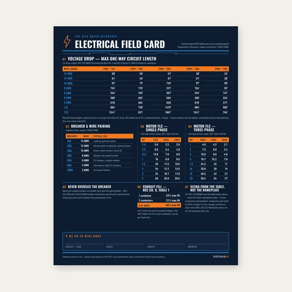
Electrical Reference Card
One page. Voltage drop lengths, breaker and wire pairing, motor FLC.
$3.99
BuyTotal resistance, branch current, voltage division — and where each wiring method shows up in real electrical work.
Series circuits force the same current through every element; parallel circuits give every branch the same voltage. Knowing which configuration you are looking at tells you how failure propagates, how load current adds, and which formula to use before you apply Ohm's Law.
Use the Series and Parallel Circuit Calculator for instant Rtotal, branch current, and voltage drop — or read the full guide below.

A series circuit has one continuous current path. Electrons flow through load after load in sequence. If any element opens — a burned-out lamp filament, a tripped limit switch, a broken conductor — current stops everywhere in that string. Total resistance is the simple sum: Rtotal = R1 + R2 + R3 + … Current is identical in every part of the loop (Itotal = I1 = I2 = …). Source voltage divides across the loads in proportion to their resistance. The largest resistor always drops the most voltage.
A parallel circuit provides multiple branches across the same two nodes. Each branch receives the full voltage between those nodes. Current splits according to each branch's resistance — lower resistance draws more current. Total resistance uses the reciprocal rule: 1/Rtotal = 1/R1 + 1/R2 + 1/R3 + … then Rtotal = 1 ÷ (that sum). Parallel total resistance is always less than the smallest individual branch resistor because you have added more paths for current.
Most practical power distribution is parallel at the branch level because you want every outlet, light, and appliance to see full line voltage independent of what else is on the circuit. Series appears where you deliberately want "all or nothing" behavior — or in simple low-voltage strings where economy outweighed redundancy.
Three resistors in series: 10 Ω, 20 Ω, and 30 Ω.
Rtotal = 10 + 20 + 30 = 60 Ω
With a 12 V source, total current is I = V / R = 12 / 60 = 0.2 A. Voltage drop across each resistor: V1 = 0.2 × 10 = 2 V, V2 = 4 V, V3 = 6 V. The drops sum to 12 V — Kirchhoff's voltage law in action.
Same three resistors in parallel: 10 Ω, 20 Ω, and 30 Ω.
1/Rtotal = 1/10 + 1/20 + 1/30 = 0.1 + 0.05 + 0.0333… = 0.1833…
Rtotal = 1 / 0.1833… ≈ 5.45 Ω
With 12 V across the parallel group, total current is Itotal = 12 / 5.45 ≈ 2.2 A. Branch currents: I10 = 1.2 A, I20 = 0.6 A, I30 = 0.4 A — they sum to the total. Use the Series and Parallel Circuit Calculator to run these numbers for up to six loads without manual math.
Two resistors in parallel: Rtotal = (R1 × R2) / (R1 + R2). Equal resistors in parallel: Rtotal = R / n where n is the number of identical branches. These shortcuts save time when verifying parallel splices or multiple identical heaters on one control voltage.
Control and interlock circuits. Safety chains often wire E-stops, door switches, and pressure switches in series so any open contact de-energizes the coil. You want the entire machine to stop when any guard opens — series delivers that logic with simple wiring.
Holiday and decorative lighting (legacy). Older incandescent mini-light strings were series chains. One bad bulb opened the string and darkened every lamp downstream — the reason those strings included "shunt" bypass wires in bulb bases. Modern LED strings often use parallel segments internally, but cheap series designs still appear in novelty lighting.
Current loops and sensing. 4–20 mA instrument loops behave as series current sources through the transmitter and receiving device. The same current flows through the loop; voltage distributes based on each device's burden resistance.
Switching multiple loads with one conductor. Switched leg wiring through several loads in series is rare in line-voltage power but appears in low-voltage HVAC controls and some indicator circuits where the designer accepted series behavior for cost or simplicity.
Residential and commercial branch circuits. Every 120 V or 277 V receptacle and lighting outlet on a branch circuit connects in parallel across the hot and neutral (or hot and hot on 240 V). Turn on the coffee maker; the adjacent outlet stays at full voltage. The breaker sees the sum of all parallel branch currents on that circuit.
Panelboard distribution. Each branch breaker feeds a parallel load group. The service entrance conductor carries the combined current of all energized parallel branches subject to diversity and load calculation rules — not a series stack of loads.
Data and communication grounding references. Equipment bonding often creates parallel paths to ground. While not "load" circuits in the Ohm's Law sense, the parallel path concept explains why multiple ground rods and bonding jumpers lower effective resistance.
After you estimate combined load current from parallel branches, size conductors with the Wire Ampacity & Derating Calculator and confirm voltage performance with the Voltage Drop Calculator.
Series symptom: entire string dead, one good device does not help. Classic holiday-light behavior. On a control chain, one open limit switch kills the whole run. Troubleshoot by measuring voltage across each element or measuring resistance segment by segment with power removed. The open element shows supply voltage across it while downstream devices read near zero.
Parallel symptom: partial operation. One tripped bedroom breaker does not affect the kitchen — separate parallel branch groups on different overcurrent devices. Within one branch, a loose splice at receptacle #3 may still leave receptacle #7 working because both are parallel taps on the same hot and neutral — unless the loose connection is on the feed-through conductor that supplies downstream devices.
Overload on parallel circuits. Each device draws its own current; totals add at the panel. Plugging too many high-watt appliances into outlets on the same branch increases Itotal even though each outlet still reads 120 V. The Ohm's Law and Power Formulas guide explains why parallel loads sum current at the breaker.
Real panels and equipment rarely stay purely one type. A string of series resistors may itself be one branch of a parallel network. Method: simplify inside-out. Reduce each series group to one equivalent resistor. Combine parallel groups with the reciprocal formula. Repeat until one Rtotal remains. Then apply I = V / R from the Ohm's Law & Power Calculator for supply current and work backward to find branch values.
Series-wired receptacles were abandoned because a single device failure removed power from everything downstream — a fire and reliability hazard in homes and workplaces. Parallel branch wiring isolates load failure to the device itself (or its local connection) while maintaining voltage for neighbors on the circuit. Parallel also prevents unintended voltage division: a series string would drop voltage across each load, so the last outlet on a chain would see far less than 120 V when upstream devices drew current.
That does not make parallel harmless. A parallel branch still shares one overcurrent device. Excessive total current heats the conductor and trips the breaker. Series interlocks remain appropriate in control circuits where intentional shutdown is the goal. Match the wiring philosophy to the failure mode you want — and always verify dead circuits before resistance measurements.
Parallel. Each outlet connects across the same two conductors (hot and neutral). Current through the breaker is the sum of all device currents on that branch.
They are wired in series. One open filament interrupts the only current path. Newer designs use parallel segments or internal shunts to avoid total outage.
Once you know V and I, power is P = V × I. If you only have R and V, find I = V / R first. The Ohm's Law calculator solves any two of V, I, R, and P.
Ohm's Law always applies to individual elements: V = I × R for each resistor. What changes is how voltage and current are distributed — shared current in series, shared voltage in parallel.
Not in an ideal parallel connection across the same two nodes — branch voltage must be equal. Different voltages mean either a series element is in the path, a poor connection is dropping voltage, or you are measuring different nodes.
One page. Voltage drop lengths, breaker and wire pairing, motor FLC.
$3.99
Buy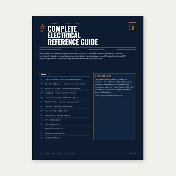
15 pages. Ampacity, corrections, voltage drop, motor circuits, conduit fill.
$12.99
Buy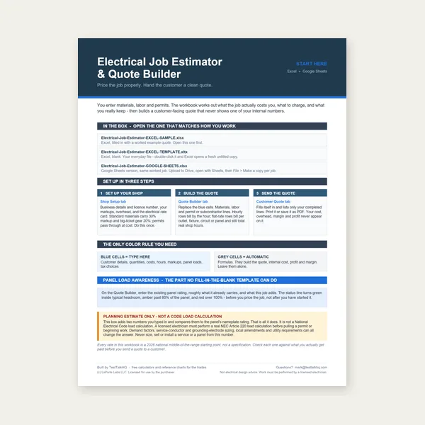
Quote electrical work and flag panel headroom before you price it.
Excel or Google Sheets. Best on a computer.
$29.00
Buy
Card, 15-page guide and the estimator workbook. All six files.
Excel or Google Sheets. Best on a computer.
$34.99
$45.98 if bought separately — save $10.99
BuyCheckout opens in a new tab.
Measure resistance and branch current to validate calculated series and parallel values in the field.

Resistance, voltage, and continuity modes let you verify calculated Rtotal on de-energized loads and measure voltage division in series strings. True RMS AC measurements help when parallel branch circuits feed motor loads or electronic power supplies rather than pure resistive elements.
Check Price
Clamp around a single parallel branch conductor to measure branch current without breaking the circuit. Compare the reading to Ibranch = V / R for that leg. True RMS response matters on branch circuits with mixed loads.
Check Price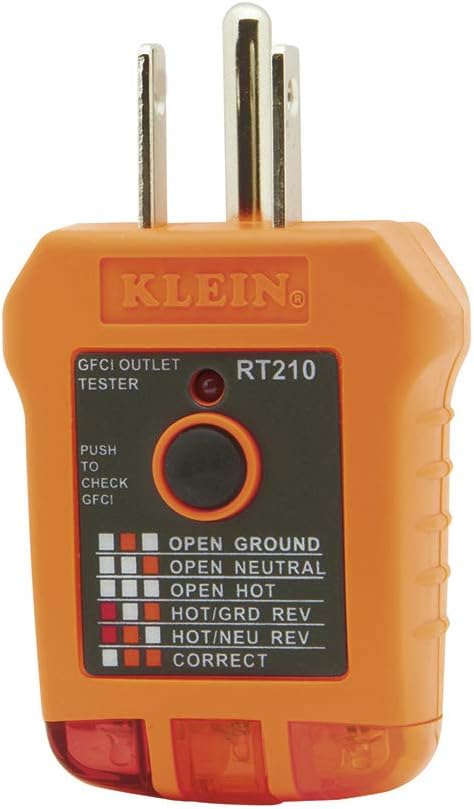
Quickly confirms parallel receptacle wiring integrity — open neutral, reversed polarity, and missing ground show up before you trust voltage readings. A fast first pass on branch circuit troubleshooting when calculated load current does not match expectations.
Check PriceAs an Amazon Associate, TestTalkHQ earns from qualifying purchases.
Early electrical installations experimented with series outlet wiring because it used less copper — current passed through each device to reach the next. The failure mode was unacceptable: one broken connection or burned-out device killed every downstream outlet. Parallel wiring runs hot and neutral as continuous feeders with each device tapped across them. Voltage stays constant at each tap; only the local device fails when its connection goes bad. The NEC and practical reliability requirements align on parallel branch topology for normal power circuits. Series remains where intentional all-or-nothing control is the safety objective.
In series, voltage splits in proportion to resistance. The highest resistance always shows the largest share of source voltage. A 90 V drop across one element in a 120 V series string means only 30 V remains for everything else — dim lamps and overheated high-resistance segments follow. Measuring voltage across each element while the circuit is energized locates the dominant resistor without disassembly. Turn power off before ohmmeter checks. Compare measured resistance to calculated values from the series formula to catch deteriorating connections before they open the chain.
Each parallel branch draws I = V / R for that branch. The breaker and feeder conductors carry the arithmetic sum of all branch currents at any instant. Two 12 A loads on the same 120 V parallel circuit need 24 A total — not 12 A. This is why plug-in load audits matter on kitchen, workshop, and server-room branches where many devices share one overcurrent device. Calculate each branch, sum the currents, then compare to breaker and conductor ampacity using the wire ampacity calculator with appropriate derating factors.
Total resistance is usually the first step, not the last. Find Rtotal with series or parallel rules, then apply Ohm's Law for supply current. From there you can find power (P = V × I), voltage drop on feeders, and fuse or breaker loading. Combination circuits require reducing series groups and parallel banks step by step until one equivalent value remains. The series-parallel calculator handles pure series or pure parallel groups; the Ohm's Law calculator picks up wherever you have two known electrical quantities and need the rest.