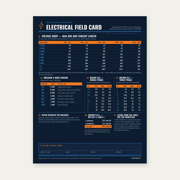
Electrical Reference Card
One page. Voltage drop lengths, breaker and wire pairing, motor FLC.
$3.99
BuyNEC 392.22 — Multiconductor & Single-Conductor Tray Fill
Enter tray type, width, cable outside diameters, and quantities to check multiconductor and single-conductor fill against NEC Table 392.22(A). See the Cable Tray Fill Guide for worked examples and field rules.

| Tray width | Ladder / ventilated | Solid bottom |
|---|---|---|
| 6" | 7.0 | 3.5 |
| 9" | 10.5 | 5.25 |
| 12" | 14.0 | 7.0 |
| 18" | 21.1 | 10.55 |
| 24" | 28.2 | 14.1 |
| 30" | 35.5 | 17.75 |
| 36" | 42.4 | 21.2 |
Single conductors in ladder/ventilated tray: sum of cable areas ≤ 40% × (width × usable depth). Solid-bottom trays require a single cable layer — no stacking.
Cable tray fill is the total cross-sectional area occupied by cables in a given tray, measured against the maximum allowable fill area permitted by NEC Article 392. Unlike conduit fill, which is expressed as a percentage of conduit interior area, cable tray fill uses absolute square-inch limits tied to tray width and tray type — limits that differ significantly depending on whether the tray is a ladder type, a ventilated trough, or a solid-bottom design. Get the fill right and the tray passes inspection with room to grow. Get it wrong and the consequences are real: conductors that run too hot degrade insulation over years of service, and an overfilled tray will stop an inspection in its tracks. Cable tray fill calculations are required on any commercial or industrial installation where cable tray is used as the wiring method — HVAC controls, process equipment feeders, data center power distribution, and panel shop sub-assembly are all common applications. Electricians, contractors, and panel shop engineers who specify tray runs need accurate fill numbers before a cable gets pulled, not after.
This calculator determines whether your cable tray installation complies with NEC 392.22 fill requirements. Enter your tray configuration and cable details, and it returns total fill area in square inches, the NEC-allowable fill area for that tray type and width, the percentage of allowable fill used, and a pass/fail determination based on the applicable NEC 392.22 subsection for your tray type and cable types.
Tray Type: Select the physical construction of the tray — ladder tray (open rungs connecting two side rails), ventilated trough (solid sides with ventilation slots in the bottom), or solid-bottom tray (fully enclosed bottom with no ventilation openings). Basket and wire mesh trays follow ladder tray rules in most applications; verify your tray listing. The fill limit in square inches is different for each type, so selecting the wrong tray type produces a meaningless result.
Tray Width: Enter the inside width of the tray in inches. NEC Table 392.22(A) provides maximum fill areas indexed to specific standard tray widths (6, 9, 12, 18, 24, 30, and 36 inches for common sizes). Use the actual inside usable width of the tray, not the outside or nominal trade width from the catalog sheet.
Cable Types: Specify whether cables are multiconductor (two or more conductors under a common jacket — power cables, control cables, tray cable, TC-ER) or single conductors (individual THWN-2, XHHW-2, or similar pulled individually). The NEC fill rules are entirely different for each type. If your tray contains a mix, the calculator handles each type under its applicable rule and evaluates them together against the combined allowable fill.
Cable Diameters: Enter the outside diameter (OD) in inches for each cable or single conductor. Use the manufacturer's published finished OD from the cable datasheet, not the conductor size alone — jacket thickness and insulation wall vary by manufacturer and cable construction, and the NEC fill rules are based on actual installed OD, not conductor gauge.
Total fill area in square inches (sum of individual cable cross-sectional areas, calculated from entered ODs). Allowable fill area for the selected tray type and width per NEC 392.22. Percentage of allowable fill used (total fill ÷ allowable fill × 100). Pass/fail flag based on NEC compliance — if total fill exceeds the allowable for any applicable rule, the result flags as a fail and indicates which limit was exceeded.
Conduit fill is based on a percentage of the conduit's interior cross-sectional area — generally 40% for two or more conductors — because conduit is a closed system with fixed thermal characteristics. Cable tray is an open raceway system, and the NEC treats it differently: fill limits are expressed as maximum allowable fill areas in square inches, derived from tray width, rather than as a percentage of the total tray interior cross-section. The open construction of a ladder or ventilated trough tray allows heat to dissipate through the top and sides of the cable stack, which is why the NEC permits more fill than a comparable conduit run. That said, the fill limit still exists because cables piled too deep on one another create a thermal mass that the open air cannot adequately cool — the center cables in a deep bundle see the same insulation degradation as overfilled conduit.
For multiconductor cables rated 2000V or less installed in ladder or ventilated trough cable trays, NEC 392.22(A)(1) requires that the sum of the cross-sectional areas of all cables not exceed the values in Table 392.22(A). The table is indexed by the inside width of the tray. For a 6-inch wide tray, the allowable fill area is 7.0 square inches. For a 12-inch tray, the allowable is 14.0 square inches. The values scale proportionally with width — effectively allowing approximately 1.17 square inches of cable fill per inch of tray width for ladder and ventilated trough trays. For intermediate widths not in the table, interpolate or use the next smaller listed width to be conservative.
Cross-sectional area for each cable is calculated from the cable's outside diameter: Area = π/4 × OD². For a cable with a 0.85-inch OD, the cross-sectional area is 0.785 × 0.85² = 0.567 square inches. Sum this value for every cable in the tray and compare the total against the table's allowable fill area for your tray width. If the sum exceeds the table value, the tray is overfilled — you must either split cables to a second tray, move some cables to conduit, or specify a wider tray before the circuit is wired.
Solid-bottom trays are more thermally restrictive than ladder or ventilated trough trays because the closed bottom reduces convective air flow under the cable bundle. NEC 392.22(A)(3) addresses this with a separate, lower fill limit for multiconductor cables in solid-bottom trays. The allowable fill area from Table 392.22(A)(3) is smaller than the equivalent ladder tray for the same inside width. Additionally, the NEC requires that cables in solid-bottom trays be installed in a single layer — cables cannot be stacked on top of one another as they commonly are in ladder tray. These two constraints together — a lower fill area limit and the single-layer restriction — mean a solid-bottom tray of a given width accommodates significantly fewer cables than a ladder tray of the same width. If your installation requires heavy cable fill and uses solid-bottom tray for mechanical protection reasons, you may need to plan for a wider tray than a ladder-tray-based fill estimate would suggest.
Single conductor cables — individual THWN-2, XHHW-2, USE-2, or similar — follow a different fill rule than multiconductor cables when installed in ladder or ventilated trough trays. Under NEC 392.22(B)(1), for single conductors rated 2000V or less and sized 1000 kcmil or smaller, the sum of the cross-sectional areas of all cables shall not exceed 40% of the interior cross-sectional area of the cable tray. The interior cross-sectional area of the tray is calculated as the inside width multiplied by the usable depth (not the nominal depth — some trays have side rails that reduce the usable fill depth). For a 12-inch wide tray with 4 inches of usable depth, the interior cross-sectional area is 12 × 4 = 48 square inches, and the allowable single-conductor fill is 48 × 0.40 = 19.2 square inches.
The 40% rule for single conductors reflects the different thermal behavior of individual conductors in an open tray: they shed heat laterally into the tray's open structure more effectively than cables bundled under a common jacket, and the 40% limit accounts for the air space needed between conductors for this to function as intended. Note that the 40% rule applies to the total interior cross-section of the tray — width times depth — not just a fill table indexed by width the way multiconductor cable fill is handled.
For single conductors larger than 4/0 AWG installed in ladder or ventilated trough trays, NEC 392.22(B) imposes a spacing requirement in addition to the fill limit. Large single conductors must be installed in a single layer and must be spaced apart from one another — they cannot be touching. The specific spacing distance is derived from the cable's own diameter. This requirement exists because large single conductors in a tightly packed bundle generate substantial heat in close proximity, and the open tray structure provides sufficient cooling only when air circulation between individual conductors is maintained. If your installation involves large single conductors — common in feeder runs to large motors, transformers, or service equipment — verify the spacing rule against NEC 392.22(B) before specifying tray width, since each cable must fit within its own footprint plus a spacing gap on each side.
NEC 392.22 addresses mixed installations — trays containing both multiconductor cables and single conductors — by requiring that each cable type comply with its applicable fill rule, and that the combined fill of both types not exceed the more restrictive of the two applicable limits. In practice, a tray containing a combination of multiconductor control cables and large single-conductor power feeders requires a dual calculation: the multiconductor portion evaluated against Table 392.22(A), and the single-conductor portion evaluated against the 40% rule, with both totals compared against the tray's capacity. The calculator handles this automatically when you specify cable types correctly for each cable entry.
The most frequent cable tray fill error is mixing multiconductor and single-conductor cables in the same tray without running separate fill calculations for each type. An electrician familiar with conduit fill may intuitively lump all cable cross-sections together and check a single total against a single threshold — but NEC 392.22 requires that multiconductor cables and single conductors be evaluated under different rules, and both must pass their respective limits simultaneously. A tray that passes the single-conductor 40% rule may still fail the multiconductor table limit if the combo calculation is not done correctly.
A second common mistake is ignoring tray depth when applying the single-conductor fill rule. The 40% fill threshold for single conductors applies to the interior cross-sectional area of the tray — width times usable depth. Electricians accustomed to the multiconductor rule (which is indexed by width alone, with depth irrelevant) sometimes calculate 40% of a width-only number and arrive at a fill allowance that is significantly lower than the actual permitted value. On a 12-inch wide tray with 4-inch depth, the correct allowable area for single conductors is 19.2 square inches, not a width-derived number.
A third error is assuming ladder and solid-bottom trays of the same width follow the same fill rules. They do not. Solid-bottom tray fill limits are lower, and the single-layer restriction applies in solid-bottom trays regardless of how deep the tray is. Using ladder tray fill numbers on a solid-bottom tray installation produces an overfill condition that will fail inspection.
No. Conduit routed through a cable tray as a mechanical protection method is not counted in cable tray fill calculations. The cables inside the conduit are protected and thermally managed by the conduit, not the tray, and NEC 392.22 fill limits apply only to cables installed directly in the tray as the raceway. However, the conduit itself physically occupies space in the tray and reduces the space available for direct-routed cables — this is a practical planning consideration even though the conduit is not part of the fill calculation.
Ladder tray and ventilated trough tray allow more cable fill than solid-bottom tray for the same inside width because the open bottom and sides of ladder and ventilated trough designs allow convective heat dissipation from all sides of the cable bundle. Solid-bottom trays restrict airflow under the cables, raising the thermal load on conductors near the bottom of the stack. NEC 392.22 reflects this by specifying lower allowable fill areas for solid-bottom trays under Table 392.22(A)(3) compared to the ladder/ventilated trough table, and by requiring that cables in solid-bottom trays be installed in a single layer — no stacking. The result is that a solid-bottom tray of a given width will hold fewer cables than a ladder tray of the same width.
Mixing power and control cables in the same tray is permitted under NEC 392.8(D) provided the power cables are rated at 600V or less, but it comes with important practical considerations. Power cables running at significant load can induce noise into low-voltage control and signal wiring through electromagnetic coupling, which can cause unreliable operation of PLCs, relay logic, and analog instrumentation. Many industrial facilities separate power and control cables into dedicated trays with a physical separation barrier, or use shielded cable for sensitive control circuits when sharing a tray is necessary. NEC does not mandate separation for 600V and below, but your equipment manufacturer's installation requirements may. Always check driven equipment specifications before routing power and control cables in common tray.
Always use the actual outside diameter (OD) published by the cable manufacturer for fill calculations. NEC 392.22 fill is based on the physical cross-sectional area the cable occupies in the tray, which is determined by the finished OD including jacket, insulation, armor, and any additional layers. The conductor size (AWG or kcmil) alone does not determine OD — two 12 AWG cables from different manufacturers or with different insulation types can have meaningfully different ODs, and those differences add up across a full tray. Use the OD from the manufacturer's published datasheet or the cable's own printed diameter marking, not a handbook estimate.
Cable tray ampacity rules are handled separately from cable tray fill rules, and they work differently than conduit fill derating. NEC 310.15(A)(3) and the associated ampacity tables provide current-carrying capacity values for cables in free air, which is the baseline used for cable tray installations because tray is considered an open raceway. However, when cables in tray are bundled closely — particularly in solid-bottom trays or when cables are stacked — NEC 310.15(B) bundling adjustments may still apply. The interaction between cable tray fill limits (which limit the total cable area) and ampacity derating (which limits current in bundled cables) must both be evaluated independently. Passing the fill limit does not automatically mean the cables are within their ampacity — verify both calculations separately for any loaded circuit in tray.
One page. Voltage drop lengths, breaker and wire pairing, motor FLC.
$3.99
Buy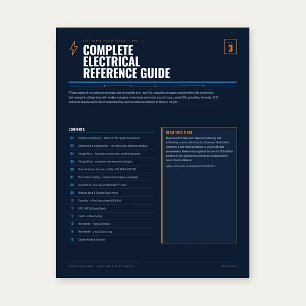
15 pages. Ampacity, corrections, voltage drop, motor circuits, conduit fill.
$12.99
Buy
Quote electrical work and flag panel headroom before you price it.
Excel or Google Sheets. Best on a computer.
$29.00
Buy
Card, 15-page guide and the estimator workbook. All six files.
Excel or Google Sheets. Best on a computer.
$34.99
$45.98 if bought separately — save $10.99
BuyCheckout opens in a new tab.
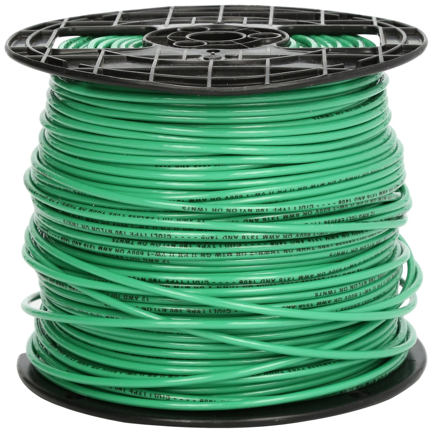
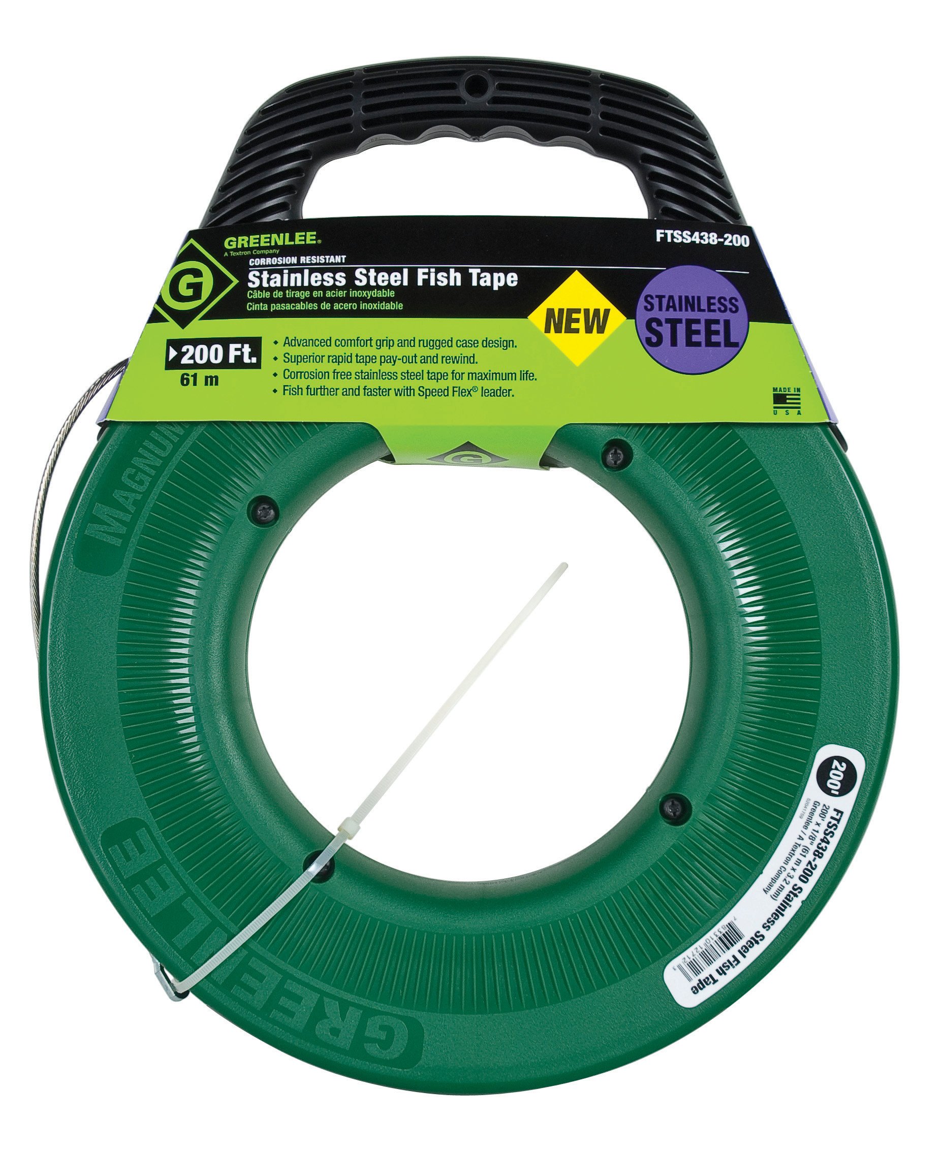
Field picks for pulling cable, stripping conductors, and verifying circuits after you size tray fill.



As an Amazon Associate, TestTalkHQ earns from qualifying purchases. Prices and availability subject to change.