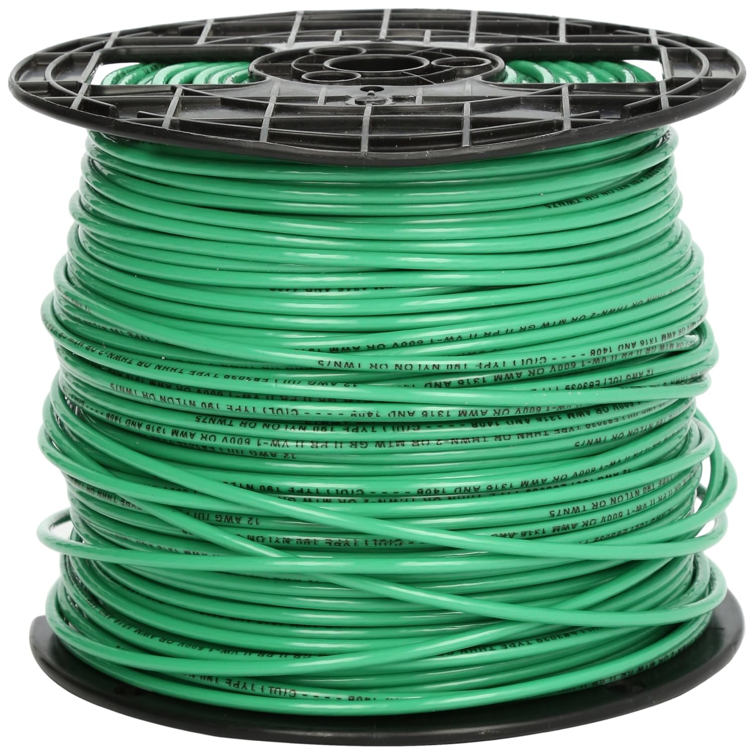
Southwire THHN 12 AWG Stranded — 500 ft
- Tray cable and homerun pulls
- Published OD for fill calculations
- UL listed spool for long runs
- Stranded — easier pulls in occupied tray
NEC 392 Rules, Formulas & Real Examples
How cable tray fill differs from conduit fill, which NEC table applies to your tray type, and how to run the math before you pull a single cable.
Try the Cable Tray Fill Calculator for instant pass/fail results from your cable schedule.

A failed cable tray fill inspection on a commercial or industrial job does not cost you just the re-inspection fee. It costs the delay before cables can be energized, the labor to re-route or remove cables that won't fit in the approved tray configuration, and the material cost of either widening the tray or running overflow circuits in conduit — all of which happens after the cable is already pulled. Overfilled trays that pass inspection but run hotter than NEC 392.22 intends cause a different problem: progressive insulation degradation at the center of the cable bundle, where heat has nowhere to go, that reduces the service life of every cable in the tray. The insulation failures show up years later, on circuits where the cause is long since forgotten. Getting cable tray fill right at the design stage — before a single cable is ordered — is the correct time to do this calculation, not during rough-in, and certainly not during inspection.
Ladder tray is the most common tray type in industrial facilities, commercial mechanical rooms, and data center overhead distribution. It consists of two longitudinal side rails connected by transverse rungs — exactly the structure the name implies. The open bottom and the gaps between rungs allow air to circulate around and beneath the cable bundle from all directions. This ventilation is why ladder tray carries the most generous fill limits of all tray types under NEC 392.22: heat generated by current-carrying cables dissipates freely upward through the open top and laterally through the rung openings. Standard rung spacing is 9 or 12 inches, and cables must have a diameter large enough to bridge between rungs without sagging into the space — a consideration for small-diameter cables in wide tray spans.
Ventilated trough tray has solid sides with ventilation openings in the bottom — typically a series of slots or perforations that cover a significant percentage of the bottom surface area. The NEC treats ventilated trough tray identically to ladder tray for fill calculation purposes because the ventilated bottom allows comparable convective airflow under the cable bundle. Where ladder tray is preferred for heavy cable loads in industrial applications, ventilated trough is commonly chosen for smaller cable populations that benefit from a solid bottom surface to prevent small-diameter cables from sagging through ladder rung gaps. The fill numbers are the same as ladder tray — use Table 392.22(A) for multiconductor cables and the 40% interior cross-section rule for single conductors.
Solid-bottom tray has a fully enclosed bottom with no ventilation openings. It provides the best mechanical protection of all tray types — cables cannot fall through, and the enclosed bottom shields cables from drips and incidental contact from below. These advantages come with a thermal penalty: without bottom ventilation, cables resting on the tray floor have no airflow beneath them. Heat from lower cables must travel up through the entire cable stack before it can dissipate. The NEC accounts for this by assigning lower allowable fill areas to solid-bottom trays in Table 392.22(A)(3) compared to the equivalent ladder tray widths, and by requiring that cables in solid-bottom trays be installed in a single layer — the stacking that is acceptable in ladder tray is not permitted here. Solid-bottom tray is common in cleanrooms, food processing facilities, and locations where liquid drip or cable fall-through is a real concern, but the designer must plan for a wider tray to accommodate the same cable population that would fit in a narrower ladder tray.
Basket tray (also called wire basket tray or wire mesh tray) is formed from welded wire in a basket profile rather than stamped or roll-formed sheet metal. It is widely used in data centers, telecommunications rooms, and light commercial applications for structured cabling and low-voltage wiring. For power cable applications, basket tray is generally treated per the ventilated trough or ladder tray fill rules under NEC 392.22, but the specific application depends on the tray's listing. Some basket tray products are listed specifically for use with data and communication cables under Article 800 and related articles rather than as a power wiring method under Article 392 — verify the tray's listing before applying NEC 392.22 fill calculations to it. Where basket tray is used as a power wiring method and is listed accordingly, it follows ladder tray fill rules.
The starting point for any cable tray fill calculation is confirming the tray type (ladder/ventilated trough vs. solid-bottom) and the inside width in inches. The fill limit in NEC 392.22 is directly indexed to inside width — not outside width, not nominal catalog width, and not the width of the tray opening where cables enter. Measure or confirm the actual inside usable width from the tray's installation instructions or specification sheet. Standard widths are 6, 9, 12, 18, 24, 30, and 36 inches for most manufactured tray products.
Determine whether each cable in the tray is a multiconductor cable (two or more conductors under a single jacket — power cable, tray cable, control cable, TC-ER, PLTC) or a single conductor (individual THWN-2, XHHW-2, USE-2, or similar). This distinction drives which fill rule applies. If your tray contains both, you will run two separate fill calculations and combine the results. Cables must be cataloged by type before the calculation can proceed.
For every cable in the tray, calculate the cross-sectional area using the cable's finished outside diameter (OD) from the manufacturer's datasheet:
Area (sq in) = π/4 × OD²
Or equivalently: Area = 0.7854 × OD². For a cable with a published OD of 0.90 inches, the cross-sectional area is 0.7854 × 0.90² = 0.7854 × 0.81 = 0.636 sq in. Calculate this for every cable individually, then sum them by type (multiconductor total and single-conductor total separately).
For multiconductor cables in ladder or ventilated trough tray (NEC 392.22(A)(1)): The sum of cross-sectional areas of all multiconductor cables must not exceed the value from NEC Table 392.22(A) for your tray width. For a 6-inch wide tray, the allowable fill area is 7.0 sq in; for a 12-inch wide tray, it is 14.0 sq in. Verify the specific value for your tray width against the current edition of NEC Table 392.22(A).
For multiconductor cables in solid-bottom tray (NEC 392.22(A)(3)): Use the allowable fill area from NEC Table 392.22(A)(3), which is lower than the ladder tray equivalent, and ensure all cables are installed in a single layer — no stacking.
For single conductors in ladder or ventilated trough tray (NEC 392.22(B)(1)): The sum of cross-sectional areas of all single conductors must not exceed 40% of the interior cross-sectional area of the tray. Calculate interior cross-section as inside width × usable inside depth. Multiply by 0.40 to get the allowable fill area. For a 12-inch wide tray with 4 inches of usable depth: 12 × 4 × 0.40 = 19.2 sq in allowable.
For single conductors larger than 4/0 AWG: An additional requirement applies — these conductors must be installed in a single layer and must be spaced apart from one another. Refer to NEC 392.22(B) for the specific spacing requirement. This is a physical layout constraint in addition to the fill area calculation.
Compare your calculated total fill area (or areas, if you have both multiconductor and single conductor cables) against the allowable values. If total fill is at or below the allowable, the tray passes NEC 392.22 for fill. If any cable type exceeds its respective limit, the tray fails — upsize the tray width, split cables to a parallel tray run, or move excess cables to conduit.
A 12-inch wide ladder tray serves a mechanical equipment room with six multiconductor cables. The cables are identified from the installation drawings and cable datasheets with the following outside diameters:
All cables are multiconductor cables under a single jacket, so NEC 392.22(A)(1) applies. Calculate the cross-sectional area of each:
| Cable | OD (in) | OD² (in²) | Area = 0.7854 × OD² (sq in) |
|---|---|---|---|
| A | 0.68 | 0.4624 | 0.363 |
| B | 0.68 | 0.4624 | 0.363 |
| C | 0.88 | 0.7744 | 0.608 |
| D | 0.61 | 0.3721 | 0.292 |
| E | 0.61 | 0.3721 | 0.292 |
| F | 0.98 | 0.9604 | 0.754 |
| Total | — | — | 2.672 sq in |
For a 12-inch wide ladder tray, NEC Table 392.22(A) provides a maximum allowable fill area of 14.0 sq in. Compare: 2.672 sq in actual fill vs. 14.0 sq in allowable. Fill used = 2.672 / 14.0 = 19.1% of allowable — PASS.
This result leaves significant capacity in the tray for future cable additions — a useful output for a facilities team planning equipment expansion. If the same calculation showed fill at 12.8 sq in, that would be 91.4% of allowable and still technically a pass, but the remaining 1.2 sq in of capacity would accommodate only a handful of small-diameter cables. Reporting fill as a percentage of allowable (rather than just pass/fail) gives designers and contractors a clear picture of headroom for future growth.
Cable tray fill and conduit fill serve the same underlying purpose — preventing thermal overload from excessive cable density — but the calculation methods, thresholds, and physical logic are entirely different. Electricians who are fluent in conduit fill per NEC Chapter 9 sometimes apply conduit fill intuitions to cable tray and arrive at wrong answers in both directions.
The most fundamental difference is that conduit fill is expressed as a percentage of the conduit's total interior cross-sectional area (40% for two or more conductors, per Chapter 9 Table 1), while cable tray fill for multiconductor cables is expressed as an absolute square-inch limit from Table 392.22(A), indexed by tray width. A 12-inch ladder tray does not have a "40% of interior cross-section" rule for multiconductor cables — it has a 14.0 sq in absolute limit, regardless of how deep the tray is. The single-conductor rule in cable tray does use a percentage of interior cross-section (40% of width × depth), but it is not the same 40% as conduit fill — the geometry is different, the rationale is different, and the two calculations are not interchangeable.
A second difference is derating behavior. Conduit fill derating under NEC 310.15(B) applies an ampacity adjustment factor when four or more current-carrying conductors share a conduit. Cable tray ampacity, particularly for cables in free air, is governed by different tables and adjustment factors that reflect the open-air thermal environment of a tray rather than the enclosed thermal environment of conduit. The fill limit and the ampacity adjustment are both required checks for any current-carrying circuit — they are not the same calculation and one does not substitute for the other.
If you are already familiar with conduit fill from the Conduit Fill Calculator, note that the cable tray calculator uses different input fields, different comparison values, and produces different output than the conduit fill tool. They are separate calculations that happen to address the same underlying concern — thermal management of current-carrying conductors — in two physically distinct raceway systems.
An inspector who sees cables piled high over the side rail height of a ladder tray — the cable stack visibly overflowing the tray structure — will flag the installation before running a single calculation. Obvious overfill is the clearest violation, but most NEC 392.22 failures are subtler: a tray that looks reasonably filled but whose cross-sectional area sum exceeds the Table 392.22(A) limit by 15 or 20 percent. This typically happens when circuits are added incrementally over the life of a project, with each individual addition appearing minor but the cumulative total exceeding the table limit. The fix is the same in either case — move cables to a parallel tray, upsize to a wider tray, or reroute overflow circuits to conduit — but discovering this at inspection is far more expensive than catching it at the design stage.
A fill calculation prepared using ladder tray allowances — then installed in solid-bottom tray because solid-bottom was substituted for mechanical protection reasons after the calculation was done — is a common source of inspection failure. The fill limit for solid-bottom tray is lower than ladder tray for the same inside width, and the single-layer restriction means a tray that was filled to 90% of the ladder tray allowance is almost certainly over the solid-bottom limit and definitely violating the single-layer rule if cables are stacked. Any mid-project change in tray type requires a recalculation before cables are pulled.
Inspectors on industrial feeder installations specifically look for the spacing requirement on single conductors larger than 4/0 AWG. Feeder cables in this size range — common for large motor feeders and service entrance conductors run in tray — must be installed in a single layer with cables spaced apart per NEC 392.22(B). An installation where these large conductors are touching one another or stacked fails on the spacing rule regardless of whether the 40% fill area calculation passes. This violation is visually obvious during inspection and is one of the first things a plan reviewer checks when single-conductor feeder schedules are shown in cable tray on the electrical drawings.
When an existing tray installation is upgraded by adding circuits to an already-loaded tray, the fill calculation is the first check — but it is not the only one. As the cable population in a tray increases, the thermal load on existing cables also increases, particularly in solid-bottom tray where heat accumulates from the bottom of the stack. Cables that were within their ampacity at original fill may require derating once additional cables are added. An upgrade that passes the revised fill calculation but ignores the ampacity impact on existing cables may result in conductors operating above their rated temperature — a violation of NEC 310.15 that does not show up on a cable tray fill inspection but will cause premature insulation failure.
The right time to run this calculation is at the design stage, when the cable schedule is being prepared and tray widths can still be adjusted without cost. Use the Cable Tray Fill Calculator to enter your cable ODs, specify your tray type and width, and get an immediate pass/fail result with fill percentage and remaining headroom. The calculator handles both multiconductor and single-conductor entries in the same tray, applies the correct NEC 392.22 rule to each, and flags any spacing requirement for large single conductors. Enter one cable at a time or build your full cable schedule — the tool processes mixed tray populations the same way an inspector would, rule by rule, so the result you get before pulling is the same result the inspector will apply at rough-in.
Pull cable, strip conductors, and verify circuits when you plan tray fill and homerun layouts.



As an Amazon Associate, TestTalkHQ earns from qualifying purchases. Prices and availability subject to change.
When the calculation looks right but inspection, packing, derating, or a live-tray add still fails, use Cable Tray Fill Troubleshooting — not another walkthrough of NEC 392.22 math.