Plasma Cutting Troubleshooting
Field differentials for top vs bottom dross, mid-cut arc dropouts, edge bevel, pierce blowback, and wet-air consumable death — when calculator amps/IPM already looked right
Not a restatement of the settings tables. Pair this with the Plasma Cutting Calculator when starting amps, speed, and pressure matched the chart but the cut still failed. For material tables and dross basics, use the Plasma Cutting Settings Guide and Plasma Cutting Settings Chart. Compressor CFM sizing lives in the Air Compressor Sizing for Plasma Cutters guide — this page stays on cut-quality diagnosis forks.
If the torch is in a gantry, the knobs are pierce height, delay, cut height, and programmed IPM — not wrist angle. Start from the CNC Plasma Calculator and the table defect map on CNC plasma cut-quality troubleshooting. This page stays on handheld torch faults.

Plasma Cut Problems Quick Answer
Use this when scrap of the same alloy/thickness was dialed to calculator IPM and PSI, and the production cut still failed. The guide lists fixes; this table splits which failure you have before you change the wrong variable.
| Problem | Field tell | First fix | Next tool |
|---|---|---|---|
| Top spatter vs bottom dross | Top: fine spray / paint-rough top edge. Bottom: rounded beads under kerf. Hard fin: thin bonded blade under edge | Top → slow 5–10 IPM or +amps. Soft bottom → speed up. Hard fin → slight speed drop + verify PSI not high | Plasma Calculator |
| Arc dies mid-cut | Notch/restart mark; gauge sag mid-plate; works on short scrap only | Watch regulator under load 20+ sec; if PSI falls → CFM/tank. Steady PSI + dropout → speed or paint/rust at transfer | Compressor Sizing Guide |
| Edge bevel > 3–5° | Cut face leans; one side of part oversized | Square torch to work; reduce standoff; inspect tip orifice roundness before blaming THC | Settings Guide |
| Pierce eats tips | Tips crater after few center pierces; blowback splash on shield | Edge-start when possible; tilt 30–45° then vertical; raise pierce standoff on ≥1/4" | Plasma Calculator |
| Settings OK, cut wild | Wavy kerf, early electrode pits, water in filter bowl | Drain dryer; replace coalescing element; dry-air test before changing amps again | Air Compressor Troubleshooting |
| Wide / uneven kerf | Micrometer kerf wider than tip rating; oval orifice | Change tip+electrode as a pair; re-check calculator IPM on scrap | Settings Chart |
1. Top Spatter vs Soft Bottom Dross vs Hard Fin — Split Before You Touch Speed
Top spatter: Fine metallic spray or paint-rough texture on the top face along the kerf. The arc is not fully clearing the thickness — travel is too fast for amps, or amps are low for thickness. Exit arc often looks vertical or leans forward.
Soft bottom dross: Rounded, globby beads hanging under the cut. Easy to chip on a slightly slow cut; welded-on if very slow. Exit arc trails more than ~15° or hangs lazy. This is the classic "too slow for amps" tell.
Hard fine bottom fin: Thin bonded blade along the bottom edge — harder to knock off than soft beads. Usually high speed + high amps pushing swirl residue to the bottom, often with PSI on the high side of the machine range.
Field differential: Top spray ≠ bottom beads. Slowing down for top spatter causes soft bottom dross. Speeding up for soft bottom dross causes top spray. Hard fin needs a small speed reduction and PSI check — not a big IPM jump.
First fix order: (1) Confirm tip/electrode not worn (oval orifice mimics every dross type). (2) Match the tell: top → −5–10 IPM or +amps; soft bottom → +5–10 IPM; hard fin → −a little speed and verify regulator PSI under load. (3) Re-run the Plasma Cutting Calculator only after consumables and air are ruled out — calculator numbers assume dry air and a sharp tip.
2. Mid-Cut Arc Dropout — CFM Sag vs Speed vs Surface Transfer
What it looks like: Arc extinguishes and restarts, leaving a notch or double-start scar. Common on long CNC nests or thick plate after a short scrap test looked fine.
Fork A — air volume / pressure sag: Tank pressure starts OK; at-machine regulator falls mid-cut; compressor never recovers before the next pierce. Short scrap works; long production cut fails. Fix: size CFM correctly (see compressor guide), shorten hose runs, fix leaks, raise tank cut-in, or lower duty (pause between pierces). Do not chase IPM until the gauge holds under a continuous 20–30 second cut.
Fork B — travel too fast for transfer: Gauge steady, but arc blows out at thick sections, corners, or rust bands. Fix: slow 5–10 IPM; ensure full transfer before moving after pierce; clean start points on painted/rusty plate.
Fork C — pilot / transfer timeout on dirty surface: Arc never fully transfers at pierce; machine times out. Fix: grind bright at start, increase pierce standoff slightly, use pilot-arc mode if equipped.
First measurement: Watch the machine regulator (not tank gauge) during a continuous cut. Falling PSI = Fork A. Steady PSI = Fork B or C. Pair with Air Compressor Sizing for Plasma and Air Compressor Troubleshooting when Fork A wins.
Scrap cuts lie about CFM. A 5-second test never shows tank recovery failure on a 40-second nest.
Plasma Compressor Guide3. Excessive Bevel & Wide Kerf — Torch Angle vs Worn Tip vs Standoff
Normal: 1–3° bevel is typical air-plasma geometry (kerf slightly wider at top).
Rejectable lean (>3–5°): Torch not square to work; standoff too high; tip orifice oval/enlarged spreading the arc; CNC cut direction fighting swirl (one side of part always fat).
Wide / uneven kerf: Micrometer across scrap kerf exceeds tip rating; wanders left-right with electrode pit wear. Settings that looked right on the calculator cannot compensate for an oval orifice.
First fix: (1) Square the torch — use a known-square scrap edge as visual reference. (2) Drop standoff toward drag-shield or 1/8" handheld / THC set-point. (3) Inspect tip orifice with light; replace tip+electrode as a pair if oval. (4) Only then re-check calculator IPM. For CNC bevel that flips with cut direction, follow OEM preferred direction — do not invent a new amperage table.
4. Pierce Blowback vs Tip Life — Edge Start vs Tilt vs Height
What it looks like: Molten metal sprays up into the tip/shield on pierce; tips crater after a handful of starts; shield face peppered.
Cause fork: Center pierce on thick plate with low standoff; no pierce delay; moving before full penetration; worn tip already weak. Not the same as mid-cut dropout — blowback is a start event.
Fixes that actually save tips: Edge-start whenever the nest allows. Must pierce in-plate: tilt 30–45°, complete pierce, then bring torch vertical. On ≥1/4", raise pierce height to 3/8"–1/2" then return to cut height. Use machine pierce delay / pierce mode. Calculator pierce time is a starting estimate — watch slag stop blowing upward before travel.
Guide-level pierce notes stay short; this page is the decision tree when tip spend is the actual failure mode.
5. Calculator Settings Right, Cut Still Wild — Moisture & Filter Path
What it looks like: Fresh tip lasts minutes; arc sputters; cut face striates even at guide IPM; water in filter bowl or icing at regulator.
Why settings pages fail here: Amps/IPM/PSI tables assume dry, filtered air. Moisture destroys hafnium inserts and makes every dross/bevel symptom appear randomly. Changing speed cannot fix wet air.
First fix order: (1) Drain tank and dryer. (2) Replace coalescing/desiccant elements on schedule. (3) Confirm filter is between compressor and plasma — not after a long wet hose. (4) Run a dry-air scrap test with new tip+electrode before touching calculator values again. Shop compressor diagnosis: Air Compressor Troubleshooting.
If the bowl is wet, stop tuning IPM. Fix air, then re-baseline on scrap.
Settings Guide6. Display Amps vs Cut Heat — Duty Cycle, Leads, Input Power
What it looks like: Machine set to calculator amps feels cold (won't sever) or hotter than scrap calibration. More common on multiprocess units and long extension cords.
Likely causes: Thermal foldback after long nests; undersized input circuit / generator sag; poor work clamp / dirty return; wrong consumable amp class for the tip installed (40 A tip on 60 A set).
Fixes: Verify tip amp rating matches setpoint. Clamp-meter the input circuit if breakers trip or lights dim mid-cut. Improve work clamp to clean metal. Let the unit cool if duty-cycle lamp is on. Re-derive from the Plasma Cutting Calculator and Settings Chart after hardware is confirmed — not while the machine is thermally limiting.
Cluster Cross-Links — Chart & Technique Already Covered
Chart SKIPPED — amperage/PSI/IPM tables already live in the Plasma Cutting Settings Chart and guide. Article 3 SKIPPED — material settings, dross basics, and technique defaults are covered in the Plasma Cutting Settings Guide; compressor selection is covered in Air Compressor Sizing for Plasma Cutters. No separate decision page rebuilt.
Plasma Cutting Calculator → Settings Guide → Settings Chart → Compressor Sizing → Cutting Speed Troubleshooting →
Recommended Tools for Plasma Cut Diagnosis
Five CSV catalog picks with verified Product Image URLs — measure kerf, tip wear, amps, and input power when cuts fail

Ideal 61-757 Clamp Meter
- Check input current under load
- Catch duty-cycle / sag issues
- True RMS for inverter cutters
- Electrical / test catalog
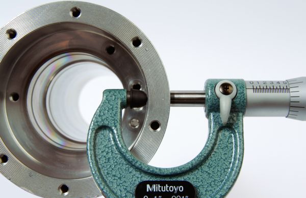
Mitutoyo 103-177 Outside Micrometer, 0–1"
- Quantify kerf width vs tip rating
- Confirm oval-orifice growth
- 0–1" shop standard
- Cutting tools / machining catalog
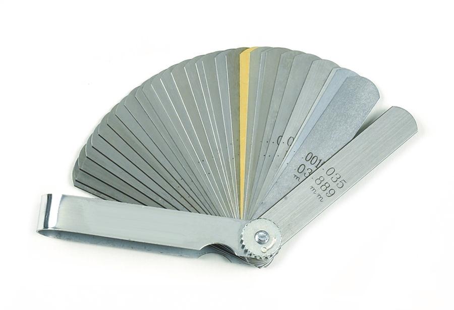
GEARWRENCH 161D 32-Blade Feeler Gauge Set
- Measure electrode pit depth
- 1/16" replace threshold checks
- 32 blades for tip/electrode QC
- Hand tools catalog

Fluke 117 Electrician's Multimeter
- Verify branch voltage under cut load
- Diagnose extension-cord sag
- Shop electrical baseline
- Electrical / test catalog
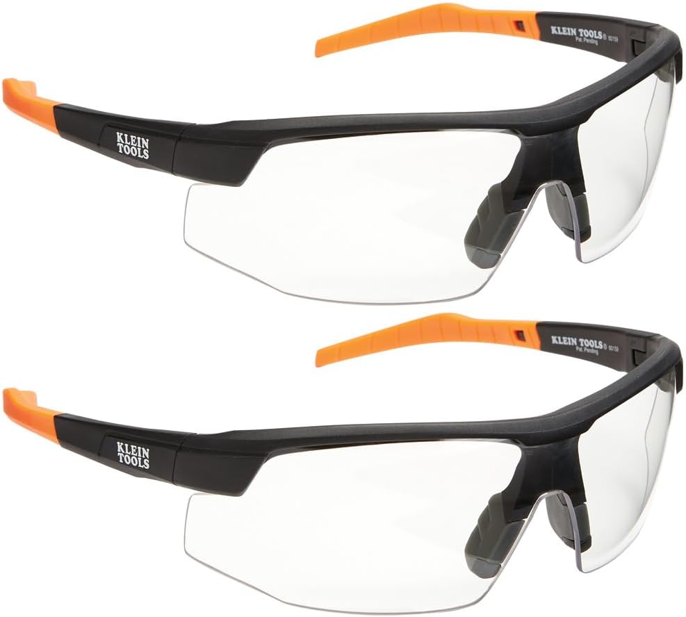
Klein Tools 60171 Safety Glasses Anti-Fog 2-Pack
- Eye protection for dross/grind cleanup
- Anti-fog for humid shops
- 2-pack for torch + helper
- Safety catalog
As an Amazon Associate, TestTalkHQ earns from qualifying purchases. All five cards are sourced only from the affiliate CSV with verified Product Image URLs. Catalog gaps flagged by name (no image URL — not shown as cards): 60PCS PT31 Plasma Consumables; PrimeWeld CT-520D; Lotos LTP8000; ARCTAYLOR CUT55P; ARCCAPTAIN CUT55 Pro; Quincy QT-54 / QT-7.5; Makita MAC2400; DEWALT / Bostitch / California Air Tools compressors; Hromee filter-regulator; LE LEMATEC regulator; Relhost air hose reel; DEWALT angle grinder.
Frequently Asked Questions
How is this different from the Plasma Cutting Settings Guide?
The guide teaches settings and lists common fixes. This page splits field presentations — which dross type, CFM sag vs speed dropout, bevel vs worn tip, pierce blowback vs mid-cut failure — and ties them to measurements before you rewrite amps.
Calculator IPM matched — why is there still dross?
Worn tip/electrode, wet air, and wrong dross fork (speeding up for top spatter) override the table. Inspect consumables and filter bowl first, then split top vs bottom vs hard fin.
When is compressor sizing the real fix?
When regulator PSI falls on long cuts but short scrap is clean. Use the plasma compressor sizing guide and air-compressor troubleshooting — do not keep lowering IPM.
Why no plasma cutter or consumable product cards?
Best CSV matches (PT31 kits, Lotos, ARCTAYLOR, ARCCAPTAIN, PrimeWeld, Quincy/Makita compressors, filter-regulators) lack Product Image URLs — flagged as catalog gaps instead of mismatched photos.
Where are the settings tables and Article 3?
Chart and Article 3 skipped — see Settings Guide, Settings Chart, and Compressor Sizing.