Cutting Speed Troubleshooting
Diagnose tool burn-up, chatter, built-up edge, chip-color lies, and RPM the machine cannot hit — when the calculator already “passed”
Not another SFM-to-RPM lesson. Pair this with the Cutting Speed & Feed Rate Calculator or Metal Cutting Speed Calculator when the math looks right and the cut still fails. For formulas and material windows use the Cutting Speed & Feed Rate Guide. For tool-material choice affecting speed capability use Carbide vs HSS Tooling. This page stays on diagnosis.

Cutting Speed Problems Quick Answer
Use this when calculated SFM/RPM is “in range” but the tool burns, the finish chatters, BUE welds to the edge, chip color contradicts the calculator, or the spindle cannot reach the number on the screen.
| Problem | What it usually means | First fix | Next tool |
|---|---|---|---|
| Tool burns up despite “correct” SFM | Hardness assumption wrong; dry cut when fluid is required; coating mismatch for the alloy | Verify material cert / Rockwell; add coolant or MQL; match coating to material | Cutting Speed Calculator |
| Chatter / poor finish despite correct speed | Feed mismatch at that RPM; fixture flex; stick-out ignored in the speed calc | Shorten overhang; raise or lower feed into a stable window; stiffen workholding | Speed & Feed Guide |
| Built-up edge (BUE) on the tool | Speed too low for gummy material; wrong rake/geometry; TiN in aluminum | Raise SFM into the shear window; polish/uncoated for aluminum; add lube | Carbide vs HSS |
| Chip color says “too hot” but calc is green | Real heat from hardness, dull edge, or dry cut — not the chart row you picked | Trust chip color as live feedback; derate SFM 15–30%; refresh edge | Speed Chart Guide |
| Calculated RPM exceeds machine max | Small diameter + high SFM needs RPM the spindle cannot deliver | Run max available RPM; compromise feed; or upsize diameter / change process | Metal Cutting Speed Calc |
1. Tool Burns Up Quickly Despite “Correct” Calculated SFM
What it looks like: Edge goes blue or purple after a short pass; carbide corners crater; HSS softens and rubs; insert life minutes instead of hours — even though RPM = (SFM × 3.82) ÷ diameter landed in the chart window.
Likely causes: Wrong hardness assumption — “mild steel” chart on heat-treated 4140, cold-drawn stock harder than annealed, or stainless work-hardened from a previous rub. Insufficient coolant or lubrication so heat stays in the edge instead of leaving with the chip. Wrong coating for the material (TiN promoting aluminum adhesion; uncoated carbide starving for heat resistance in dry steel). Dull edge from a previous job programmed at new-tool SFM.
Fixes: Confirm the material cert or spot-check hardness before trusting a generic SFM row. Flood, mist, or cutting fluid when the alloy demands it — calculated SFM assumes heat leaves the zone. Match coating: polished/uncoated for aluminum; AlTiN/TiAlN for dry steel. If the tool is already heat-tinted, replace it before re-running the same “correct” number on a dead edge.
2. Chatter or Poor Surface Finish Despite Correct Speed Calculation
What it looks like: Harmonic rings, washboard marks, squeal, or torn finish while RPM matches the calculator and SFM is in the book range.
Likely causes: Feed rate mismatch at that RPM — speed alone does not set stability; IPT × flutes × RPM must land in a cutting window, not a rub-or-overload band. Insufficient rigidity: vise on parallels, thin walls, worn spindle bearings, or a Bridgeport with backlash. Tool overhang not accounted for — the calculator converts SFM to RPM by diameter only; a 4×D stick-out chatters at speeds a stubby tool loves.
Fixes: Shorten overhang before rewriting the entire SFM chart. Adjust feed ±10–20% while holding RPM to find a quiet pocket. Clamp closer to the cut; use a stub holder or reduce DOC/WOC until the system stops singing. If IPT is the real failure (welding, powder chips), branch to Chip Load Troubleshooting — that is feed-per-tooth diagnosis, not SFM math.
3. Built-Up Edge (BUE) Forming on the Tool
What it looks like: Workpiece material welded to the cutting edge; torn or smeared walls; edge looks “fatter” after a pass; finish tears even though RPM seems conservative.
Likely causes: Speed too low for the material — especially aluminum, soft steel, and copper alloys — so the chip pressure-welds instead of shearing cleanly. Wrong tool geometry (negative rake where positive is needed; packed flutes). Coating affinity: TiN in aluminum is a classic BUE promoter. Dry cut when wax or mist would break the weld.
Fixes: Raise SFM into the upper half of the material window until chips curl bright and leave the edge clean. Prefer polished or uncoated carbide in aluminum. Add dry lube or flood. If BUE returns immediately after cleaning the flute, you are still below the shear threshold or still on the wrong coating — not “almost right.”
Need RPM from a higher SFM target? Re-run diameter and material in the calculator after you decide to climb the speed window — do not guess RPM from memory.
Cutting Speed Calculator4. Chip Color / Formation Says Wrong Parameters Despite Calculator “Passing”
What it looks like: Blue, purple, or black chips in steel when the sheet says you are mid-range; powder instead of curls; long stringy birds-nests that wrap the tool — while the UI still shows a green SFM result.
Likely causes: Blind trust in the calculation. Charts assume average hardness, sharp tools, adequate coolant, and typical engagement. A dull edge at “correct” SFM runs hotter than a sharp edge at the same RPM. Dry machining of steel at a wet-machining chart row. Chip color is a real-time pyrometer; the calculator is a starting guess.
Fixes: Read chips first, numbers second. Silver/straw curls in steel with a crisp sound usually mean you are close. Deep blue/purple means derate SFM 15–30% or restore coolant and edge sharpness, then re-check. Powder = rubbing (often feed too low at that RPM). Use the Metal Cutting Speed Chart Guide for reference windows, then scrap-tune — do not treat a calculator pass as proof the cut is healthy.
5. Calculated RPM Exceeds Machine Capability
What it looks like: Calculator returns 12,000+ RPM for a small carbide mill in aluminum; your mill tops out at 4,000 or your drill press at 3,000; operators either ignore the number or force a half-speed compromise without adjusting feed.
Likely causes: Real-world machine limitation not in the formula. SFM × 3.82 ÷ diameter has no max-RPM input. Small diameters at high aluminum/brass SFM demand spindle speeds hobby and older industrial machines cannot deliver. Running max RPM at full chart feed can overload a soft machine; running max RPM at timid feed rubs and burns.
Fixes: Cap RPM at the machine maximum, then recalculate effective SFM: SFM_actual ≈ (RPM_max × diameter) ÷ 3.82. Accept lower surface speed — productivity drops, tool life usually survives if feed is still shearing. Reduce feed proportionally so IPT stays in window, or upsize tool diameter so the same SFM needs less RPM. For thermal cutting methods (plasma, oxy-fuel, saws) use the Metal Cutting Speed Calculator process windows instead of forcing a milling SFM onto a torch or blade.
Decision: Carbide vs HSS — Does Tool Material Change the Speed Window?
Same material, opposite speed capability: carbide holds hardness at temperatures that soften HSS, so chart SFM jumps 3–5× on rigid setups — and chips or chatters on loose ones. If the “speed problem” is really the wrong tool substrate for your machine, fix the tooling choice first.
Recommended Cutting Tools & Machining Gear
Five catalog picks from Cutting Tools / Machining — end mills, tap/die, reamer, parting, and setup tools that support speed/feed diagnosis
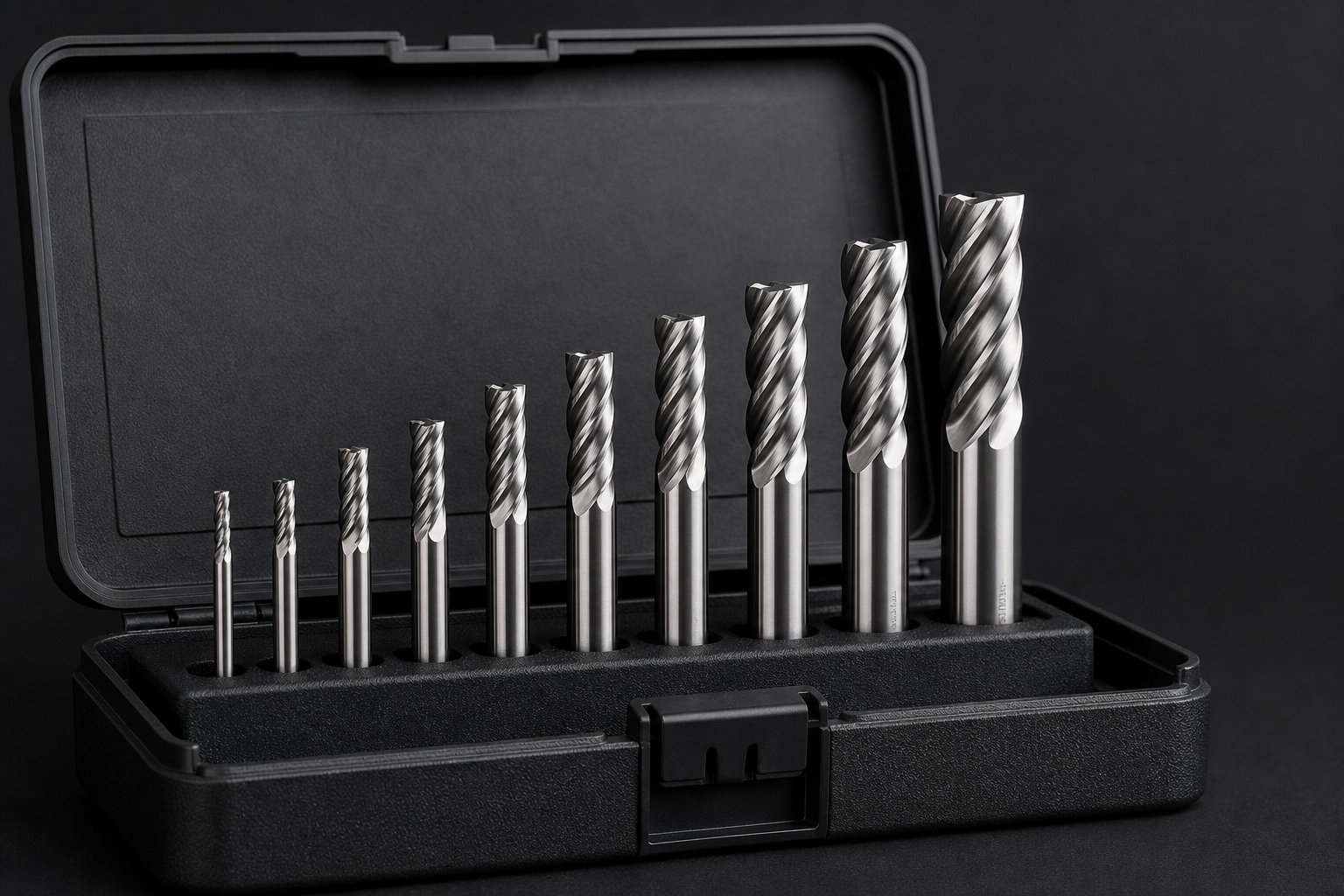
RIP Cutting Tools 6-PC 4-Flute Carbide End Mill Set (1/8"–1/2")
- Replace heat-burned cutters before re-testing SFM
- 4-flute carbide for steel speed windows
- 1/8"–1/2" covers RPM-cap and burn-up cases
- Cutting Tools / Machining catalog

Hi-Spec 39 Piece SAE & Metric Tap and Die Set
- Threading speeds differ from milling SFM
- SAE + metric coverage for shop threads
- Replace dull taps that fake “speed” failures
- Cutting Tools / Machining catalog
OMEX 8-Piece Expanding Adjustable Hand Reamer Set (15/32"–1.1/16")
- Finish holes after drill-speed diagnosis
- Expanding range for shop ID work
- Hand reaming avoids spindle RPM limits
- Cutting Tools / Machining catalog
Lathe Grooving/Parting Tool Holder MGEHR1212-3 with 10 Carbide Inserts
- Turning SFM + feed on cutoff operations
- Carbide inserts for higher surface speed
- Fresh edges stop false “burn” diagnoses
- Cutting Tools / Machining catalog
SHARS Wiggler Edge/Center Finder Set
- Accurate location reduces forced overhang
- Better setups cut chatter at “correct” SFM
- Edge find before blaming the speed chart
- Cutting Tools / Machining catalog
As an Amazon Associate, TestTalkHQ earns from qualifying purchases. All five cards are sourced from the Cutting Tools / Machining category in the affiliate CSV.
Frequently Asked Questions
The calculator says my SFM is fine — why is the tool burning?
Confirm hardness vs the chart row, coolant path, coating, and edge condition. Generic SFM assumes average stock and a sharp tool. Blue chips or a tinted edge are live heat data — derate or fix lubrication before raising speed further.
Why do I get chatter at the “correct” RPM?
Speed is only one leg. Feed mismatch, long stick-out, and soft workholding cause chatter at chart SFM. Shorten overhang and tune feed before rewriting material tables.
Is built-up edge always from running too fast?
Often the opposite in aluminum and soft steels — too low SFM plus wrong coating welds material to the edge. Raise into the shear window and drop TiN in aluminum.
Should I trust chip color or the calculator?
Chip color wins for real-time diagnosis. Use the calculator to pick a start; use chips to confirm you are actually in a healthy heat window.
What if my machine cannot reach calculated RPM?
Run max available RPM, compute actual SFM, and reset feed for that speed — or change diameter/process. Do not keep chart feed attached to an unreachable RPM.
Is this the same as the Cutting Speed Guide?
No. The guide teaches SFM/RPM/feed formulas and material windows. This page diagnoses failures when the calculation already looks correct.