Metal Cutting Speed Chart Guide: Calculate SFM, RPM & Feed Rates for Optimal Tool Life
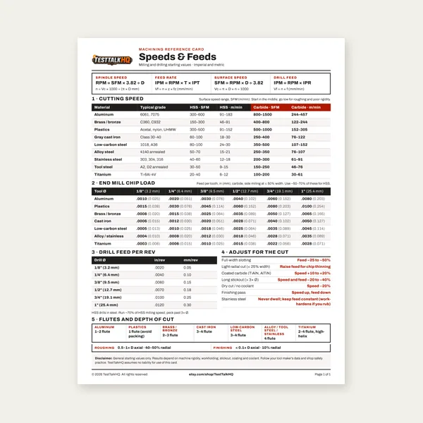
Wrong RPM on a given diameter means wrong SFM—then heat kills edges fast. Look up SFM for material + tool, convert to RPM with diameter, set feed to actually cut (not rub). This page is the shop-floor chart stack plus the conversion math your calculator cluster already automates.
You’re running a lathe at 800 RPM cutting mild steel with a high-speed steel (HSS) tool bit, and the tool is smoking, turning blue, and dull after just 30 seconds—which means you’re running at least 2-3x too fast and destroying expensive tooling through heat buildup. Proper cutting speed for HSS on mild steel is 80-100 surface feet per minute (SFM), which on a 2-inch diameter workpiece translates to just 150-190 RPM, not 800. That single speed miscalculation just cost you a $15-30 tool bit and 20 minutes of setup time re-tooling the lathe.
Cutting speed and feed rate determine everything in machining: tool life, surface finish quality, cutting efficiency, and whether your expensive carbide insert lasts 200 parts or breaks on the third cut. Running too fast creates excessive heat that hardens the work material (work hardening), welds chips into tool gullets, and rapidly dulls cutting edges. Running too slow wastes time, causes poor surface finish, and creates work hardening through rubbing instead of cutting. The difference between optimal cutting speeds and guesswork is the difference between predictable tool life and constant frustration.
This guide shows you how to calculate cutting speed (SFM) and spindle speed (RPM) for lathes, mills, drills, and saws using diameter and material type, provides complete speed and feed charts for HSS and carbide tools on steel, aluminum, stainless steel, brass, and titanium, and explains how to read chip formation to diagnose speed and feed problems. You’ll learn why carbide tooling runs 3-5x faster than HSS, how material hardness affects cutting speed (annealed vs hardened steel requires 40-60% speed reduction), and the five critical signs that indicate you need to adjust your speeds or feeds.
Roughing-friendly mid-range SFM from the charts below—verify with toolmaker/WPS, coolant, and rigidity. RPM uses workpiece or cutter diameter D in inches (lathe OD, mill cutter, drill body).
Material
HSS SFM
Carbide SFM
Starting RPM rule
Notes
Mild steel
80–100
400–600
RPM = (SFM × 3.82) ÷ D″
Flood coolant helps carbide; don’t “guess” RPM without D.
Cutting speed directly determines tool life, surface finish quality, and machining efficiency. Too fast and you generate excessive heat that destroys tooling. Too slow and you waste time while causing poor finishes and potential work hardening.
The Cost of Incorrect Cutting Speed
Real-world example: Machine shop running carbide inserts on steel
Scenario: Facing operation on 4-inch diameter mild steel, carbide insert
Wrong speed (guessing): 1,200 RPM
Actual SFM: 1,257 SFM (way too fast!)
Recommended SFM for carbide: 400-600 SFM
Result: Insert edge breaks on third part, $15 insert wasted
Tool life: 3 parts before failure
Correct speed (calculated): 450 RPM
Actual SFM: 471 SFM (optimal range)
Result: Clean cuts, excellent finish
Tool life: 200+ parts before edge wear requires indexing
Cost per part: $0.075 (insert cost ÷ 200 parts)
Annual impact (500 parts/month):
Wrong speed: 167 inserts/month @ $15 = $2,505/month in tooling
Correct speed: 2.5 inserts/month @ $15 = $37.50/month in tooling
Annual savings: $29,610 in tooling costs alone
This doesn’t include downtime for tool changes, rejected parts from poor finish, or operator frustration.
Maximum tool life: Tools last 10-100x longer than at wrong speeds
Best surface finish: Smooth, consistent cuts
Predictable performance: Consistent results part after part
Efficient cutting: Material removes quickly without excessive heat
Proper chip formation: Chips break cleanly and evacuate
SFM vs. RPM: Understanding the Difference
The most critical concept in machining is understanding the difference between SFM (surface feet per minute) and RPM (revolutions per minute). These are NOT the same thing, and confusing them destroys tooling.
What is SFM (Surface Feet Per Minute)?
SFM = speed at which the cutting edge moves past the work material.
SFM is the linear speed at the cutting point where tool meets material. This is the number that matters for cutting—it determines heat generation, tool wear, and cutting efficiency.
Think of it this way: If you could unroll the circumference of a spinning workpiece and measure how many feet per minute the surface travels, that’s SFM.
Example: A 4-inch diameter bar spinning at 300 RPM has a surface speed of 314 SFM.
SFM stays constant regardless of diameter for a given material/tooling regime—but the RPM required changes with diameter.
What is RPM (Revolutions Per Minute)?
RPM = rotational speed of spindle or workpiece.
RPM is simply how fast something spins. This is what you set on the lathe, mill, or drill press. RPM alone means nothing without knowing diameter.
Critical insight: 500 RPM creates vastly different cutting speeds depending on diameter:
500 RPM on 1″ diameter = 131 SFM
500 RPM on 4″ diameter = 524 SFM
500 RPM on 8″ diameter = 1,047 SFM
Same RPM, but 8x difference in actual cutting speed!
Why This Matters
Machine operators set RPM. Tool manufacturers specify SFM. You must convert between them based on workpiece or tool diameter.
The workflow:
Look up recommended SFM for your material and tool type
Measure workpiece or tool diameter
Calculate required RPM using the formula
Set machine to that RPM
Skip this conversion and you’re guessing—which usually means destroying tooling.
How to Calculate Cutting Speed (SFM)
If you know RPM and diameter, you can calculate actual cutting speed (SFM) to verify you’re in the correct range.
SFM Calculation Formula
SFM = (Diameter in inches × π × RPM) ÷ 12
Or simplified:
SFM = (Diameter × 3.14159 × RPM) ÷ 12
Even more simplified (approximation):
SFM ≈ (Diameter × RPM) ÷ 3.82
Step-by-Step SFM Calculation
Example: Turning 3-inch diameter steel bar at 400 RPM
Step 4: Set machine to nearest available speed — If lathe has 150, 200, 250 RPM settings, choose 200 RPM (closest to 172).
RPM Changes as Diameter Changes
On a lathe, as you reduce diameter, you must increase RPM to maintain constant SFM.
Example: Turning down a bar from 3″ to 1″ diameter — Target SFM: 90 (mild steel, HSS)
Diameter
Required RPM
Why it changes
3″
115 RPM
Large diameter, surface moves fast
2″
172 RPM
Smaller, need more RPM for same SFM
1″
344 RPM
Small diameter needs high RPM
Professional machinists adjust RPM throughout a turning operation to maintain optimal SFM as diameter decreases.
Cutting Speed Charts by Material
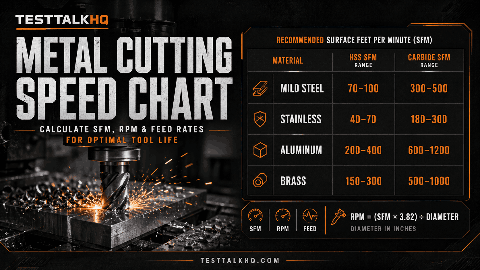
These charts provide recommended SFM for common materials with HSS and carbide tooling.
Mild Steel (1018, A36, 1045)
Tool Material
Roughing SFM
Finishing SFM
Typical Tool Life
HSS (High-Speed Steel)
80-100
100-120
60-90 min
Carbide (uncoated)
400-600
600-800
45-60 min
Carbide (TiN coated)
500-700
700-900
60-90 min
Carbide (TiAlN coated)
600-800
800-1,000
90-120 min
Stainless Steel (304, 316, 17-4 PH)
Tool Material
Roughing SFM
Finishing SFM
Notes
HSS
40-60
60-80
Work hardens easily
Carbide (uncoated)
200-300
300-450
Use heavy feed
Carbide (coated)
250-400
400-550
Sharp tools critical
Critical for stainless: Stainless work hardens rapidly. Use sharp tools, adequate feed rates, and consistent cutting—no dwelling or rubbing.
Aluminum (6061, 7075, 2024)
Tool Material
Roughing SFM
Finishing SFM
Notes
HSS
300-500
500-800
Use high positive rake
Carbide
800-1,200
1,200-1,800
Can run very fast
PCD (Polycrystalline Diamond)
1,500-3,000
3,000-5,000
Production only
Aluminum notes: Aluminum cuts fast but is “sticky”—chips tend to weld to tools. Use sharp tools with polished flutes and flood coolant.
Titanium (6Al-4V, CP Grades)
Tool Material
Roughing SFM
Finishing SFM
HSS
30-50
50-70
Carbide (uncoated)
80-150
150-250
Carbide (TiAlN coated)
150-250
250-350
Titanium notes: Extremely tough, generates heat, work hardens. Use flood coolant, sharp tools, and consistent cutting. Never dwell.
Brass and Bronze
Material
HSS SFM
Carbide SFM
Free-machining brass (360)
300-500
600-1,000
Leaded brass
200-400
500-800
Bronze (bearing)
100-200
300-500
Aluminum bronze
50-80
150-300
Tool Steel (O1, A2, D2, M2)
Condition
HSS SFM
Carbide SFM
Annealed (soft)
60-80
250-400
Hardened (45-50 HRC)
30-50
150-250
Hardened (55-60 HRC)
15-30
80-150
Hardened (60-65 HRC)
Cannot cut
40-80 (special grades)
Critical: Always machine tool steel in annealed condition when possible. Hardened tool steel requires carbide or CBN (cubic boron nitride) tooling.
HSS vs. Carbide Speed Comparison
Understanding the difference between HSS and carbide tooling is critical for selecting appropriate cutting speeds.
High-Speed Steel (HSS)
Properties:
Made from alloyed steel (tungsten, molybdenum, chromium, vanadium)
Can be sharpened to extremely sharp edges
Tough (resists breaking)
Loses hardness at 1,000-1,100°F
Relatively inexpensive ($10-40 per tool)
Cutting speed: 50-500 SFM depending on material. Best for: Manual lathes, mills without rigid tooling, interrupted cuts, small shops.
Carbide (Cemented Tungsten Carbide)
Properties:
Made from tungsten carbide powder bonded with cobalt
Extremely hard (stays sharp at high temperatures)
Brittle (chips/breaks under shock loads)
Maintains hardness up to 1,800-2,000°F
Expensive ($15-60 per insert)
Cutting speed: 200-3,000 SFM depending on material and coating. Best for: CNC machines, rigid setups, production runs, continuous cuts.
Speed Multiplier: HSS to Carbide
General rule: Carbide runs 3-5x faster than HSS on the same material.
Material
HSS SFM
Carbide Multiplier
Carbide SFM
Mild steel
90
5-6x
450-540
Stainless
50
5-6x
250-300
Aluminum
400
2-3x
800-1,200
Titanium
40
3-5x
120-200
Cast iron
60
4-6x
240-360
Feed Rates and Feed Per Tooth
Cutting speed (SFM) and feed rate work together. Speed determines how fast the tool moves across the material, feed rate determines how much material is removed per revolution.
What is Feed Rate?
Feed rate = distance the tool advances per revolution (lathe) or per tooth (mill).
Lathe feed rate: Inches per revolution (IPR). Example: 0.010 IPR means tool advances 0.010″ for every spindle revolution.
Mill feed rate: Inches per minute (IPM). Calculated from: Chip load × Number of teeth × RPM.
Why: Both speed and feed generate heat. Combined heat must stay below tool failure temperature.
Example: Turning mild steel with carbide — High speed (600 SFM): use light feed (0.010 IPR) to control heat. Medium speed (450 SFM): use moderate feed (0.018 IPR) balanced. Low speed (300 SFM): use heavy feed (0.025 IPR) to avoid rubbing.
Harder materials generate more heat, create higher cutting forces, wear tools faster, and risk work hardening when speeds/feeds are wrong.
Professional tip: Always machine materials in their softest state. Heat treat AFTER machining whenever possible.
Reading Chip Formation
Chips tell you everything about whether your speed and feed are correct. Learn to read chips and you’ll diagnose problems instantly.
Ideal Chip Formation
What to look for: Long, curled, consistent chips; light straw to light blue (HSS), blue to purple acceptable (carbide); warm to hot, but not smoking; chips break cleanly every 2-6 inches; every chip looks the same.
What this means: Speed and feed are optimal; tool is cutting efficiently.
Problem Chip Formations
Fine, powdery chips — Cause: speed too slow, feed too light. Fix: increase speed 20-30% OR increase feed 50-100%.
Heavy, thick chips that are charred or smoking — Cause: speed too high. Fix: reduce speed 20-30%, add coolant, check for dull tool.
Chips welded to tool or gullet packing — Cause: speed too high (chips melting), insufficient coolant. Fix: reduce speed 25%, increase coolant flow, use chip breaker geometry.
Long stringy chips — Cause: feed too light, wrong chip breaker. Fix: increase feed rate, use insert with aggressive chip breaker.
Segmented or “C-shaped” chips — Cause: work hardening, tool dull or chipped. Fix: replace tool, increase feed to stay ahead of work hardening.
Chip Color Guide (Steel)
Chip Color
Temperature Range
Diagnosis
Silver/white
<400°F
Too slow, rubbing
Straw/gold
400-500°F
Ideal for HSS
Light blue
500-600°F
Upper range HSS, OK for carbide
Dark blue/purple
600-750°F
Too hot for HSS, acceptable for carbide
Black/smoking
>800°F
Way too fast, destroying tool
Bandsaw Cutting Speeds
Bandsaws operate differently from other machine tools—they use blade speed (feet per minute) rather than spindle RPM.
Bandsaw Blade Speed Recommendations
Material
Blade Speed (FPM)
Feed Pressure
Notes
Mild steel (soft)
200-300 FPM
Medium
Fast, efficient cutting
Alloy steel (annealed)
150-250 FPM
Medium-heavy
Slower than mild steel
Tool steel (hardened)
80-150 FPM
Light-medium
Slow speed, light pressure
Stainless steel
100-200 FPM
Heavy
Keep blade engaged, no dwelling
Aluminum
300-500 FPM
Light-medium
Fast cutting, watch chip clogging
Brass/bronze
200-350 FPM
Medium
Clean, fast cuts
Titanium
50-120 FPM
Light
Very slow, use coolant
Cast iron
150-250 FPM
Medium
Abrasive material, wears blades
Portable Bandsaw Speeds
Most portable bandsaws (Milwaukee, DeWalt, Makita) have 2-3 speed settings:
The problem: Running carbide inserts at HSS speeds (90 SFM instead of 450 SFM).
Fix: Use carbide speed charts, typically 4-6x HSS speeds for steel, 2-3x for aluminum.
Mistake #4: No Speed Adjustment for Material Hardness
The problem: Cutting annealed steel at 500 SFM, then cutting hardened steel at same speed.
Fix: Always verify material hardness. Reduce speed 15-20% for every 10 points of hardness increase.
Mistake #5: Ignoring Chip Formation
The problem: Continuing to cut even when chips are smoking, powdery, or welded to tool.
Fix: Stop and inspect chips every few minutes when setting up a new job. Adjust speed/feed until chips are correct.
Frequently Asked Questions
What is the difference between SFM and RPM?
SFM (surface feet per minute) is the linear speed at which the cutting edge moves past the material—this determines heat generation and tool wear. RPM (revolutions per minute) is how fast the spindle or workpiece rotates. The same RPM creates vastly different SFM depending on diameter: 500 RPM on 1″ diameter = 131 SFM, but 500 RPM on 4″ diameter = 524 SFM. Always convert recommended SFM to RPM using: RPM = (SFM × 3.82) ÷ Diameter. Use our Metal Cutting Speed Calculator for instant conversions.
How do you calculate cutting speed in SFM?
Calculate SFM using: SFM = (Diameter in inches × π × RPM) ÷ 12, or simplified: SFM ≈ (Diameter × RPM) ÷ 3.82. Example: 3-inch diameter bar spinning at 400 RPM = (3 × 400) ÷ 3.82 = 314 SFM. This tells you actual cutting speed to compare against manufacturer recommendations. For mild steel with HSS tooling (recommended 80-100 SFM), 314 SFM is too fast—reduce RPM to 100-120 for optimal cutting.
What cutting speed should I use for mild steel?
Mild steel (1018, A36) cuts at 80-100 SFM with HSS tooling or 400-600 SFM with carbide inserts. For example, turning a 2-inch diameter mild steel bar with HSS requires 90 SFM = 172 RPM. The same operation with carbide at 500 SFM requires 955 RPM. Carbide runs 5-6x faster than HSS on steel. Always use flood coolant with carbide for maximum tool life and verify you’re using correct insert grade for your material.
Why do carbide tools run faster than HSS?
Carbide maintains hardness up to 1,800-2,000°F while HSS loses hardness above 1,000-1,100°F. This heat resistance allows carbide to run 3-6x faster than HSS depending on material. On mild steel, HSS runs 80-100 SFM while carbide runs 400-600 SFM. The speed advantage increases productivity dramatically—carbide can make cuts in 1/5 the time of HSS. However, carbide is brittle and chips easily under shock loads, making it best for rigid CNC setups rather than manual machines with play or chatter.
How does material hardness affect cutting speed?
Harder materials require proportionally slower cutting speeds. For every 10 points of Rockwell C hardness increase, reduce speed 15-20%. Example: 4140 steel annealed at 20 HRC cuts at 500 SFM carbide, but hardened to 50 HRC requires reducing speed to 180-220 SFM (60% reduction). Tool steel at 60+ HRC may require 70-80% speed reduction and special carbide grades. Always machine materials in their softest (annealed) state before heat treating whenever possible.
What do chip colors mean when machining?
Chip colors indicate cutting temperature: straw/gold (400-500°F) is ideal for HSS, light blue (500-600°F) is acceptable for carbide, dark blue/purple (600-750°F) indicates borderline too hot for HSS but OK for carbide, and black or smoking chips (800°F+) mean way too fast and tool destruction imminent. Silver/white chips indicate too slow (rubbing, not cutting). Aim for light straw to light blue chips on steel. Chips should curl consistently, break cleanly every 2-6 inches, and feel warm but not smoking hot.
How do I know if my speed and feed are correct?
Correct speed and feed produce long, curled, consistent chips that are light straw to blue color, warm but not smoking, and break cleanly every few inches. Tool should cut smoothly without chatter or excessive vibration. Surface finish should be smooth and even. If chips are powdery (too slow), smoking/charred (too fast), or welded to tool (way too fast), adjust immediately. Run test cuts when setting up new operations and inspect chips before committing to full production runs.
What bandsaw blade speed should I use for steel?
Mild steel cuts at 200-300 FPM on horizontal bandsaws, tool steel (hardened) requires 80-150 FPM, and stainless steel cuts at 100-200 FPM. Portable bandsaws typically have low (80-120 FPM) for hard materials, medium (200-250 FPM) for general steel, and high (300-350 FPM) for soft metals like aluminum. Always use slow speeds on hardened materials and heavy feed pressure on stainless to prevent work hardening. Use cutting fluid on all materials except cast iron for maximum blade life.
Can I use the same cutting speed for stainless as mild steel?
No, stainless steel requires 40-50% slower cutting speeds than mild steel because it work hardens rapidly and generates more heat. Mild steel with carbide runs 500-600 SFM, but 304 stainless requires 250-350 SFM. Additionally, stainless needs higher feed rates (paradoxically) to stay ahead of work hardening—use aggressive feeds and sharp tools. Never let tool dwell or rub on stainless as this instantly work hardens the surface, making it nearly impossible to cut. Use flood coolant and sharp tools exclusively.
What happens if I run cutting speed too fast?
Excessive speed generates heat that: (1) rapidly dulls or destroys cutting edges (tools turn blue, lose hardness), (2) work hardens the material surface (makes it impossible to cut), (3) welds chips to tool gullets (chip recutting damages surface finish), (4) causes catastrophic tool failure (carbide inserts chip or shatter), and (5) creates poor surface finish from chatter and heat distortion. Tools running too fast smoke, turn dark blue/black, and fail in seconds to minutes instead of lasting 45-90 minutes. Reduce speed 20-30% if you see any smoking, charred chips, or rapid tool wear.
Do I need cutting oil?
For many steels and stainless jobs, yes—flood coolant or cutting oil reduces heat, improves surface finish, and extends tool life. Aluminum often wants excellent evacuation + coolant to control chip welding. Cast iron is often cut dry. Match fluid to material/WPS and don’t substitute “more RPM” for missing coolant when the process expects it.
Conclusion: Master Cutting Speeds for Predictable Results
Cutting speed and feed rate are the foundation of successful machining—get them right and tooling lasts hundreds of parts with excellent finishes, get them wrong and tools fail in minutes with scrapped work. The difference between a $15 carbide insert lasting 3 parts versus 200 parts is understanding that mild steel cuts at 80-100 SFM with HSS (172 RPM on 2″ diameter) or 500 SFM with carbide (955 RPM), not guessing and running at 800 or 1,200 RPM which destroys tooling through excessive heat.
Key takeaways for optimal cutting speeds:
Always convert recommended SFM to RPM using diameter—same RPM creates vastly different cutting speeds on different diameters
Carbide runs 3-6x faster than HSS on steel (500 SFM vs 90 SFM) but requires rigid setups to avoid chipping
Adjust RPM as diameter changes on lathes—maintain constant SFM by increasing RPM as diameter decreases
For beginners, start with conservative speeds (use lower end of recommended SFM range) and work up while monitoring chip formation. For production work, document optimal speeds and feeds for each material-tool combination to ensure consistent results across multiple operators and shifts.