Chip Load Troubleshooting
Diagnose chip welding, breakage despite “correct” IPT, poor finish, premature wear, and charts that lie on your machine
Not another definition of feed per tooth. Pair this with the Chip Load Calculator when the math looks right and the cut still fails. For formulas and chart reading use the Chip Load Guide. For climb vs conventional direction (and how it changes chip formation) use Climb vs Conventional Milling. This page stays on diagnosis.

Chip Load Problems Quick Answer
Use this when the calculator IPT is “in range” but chips weld to the tool, corners chip, finish is rough, edges die early, or generic charts never match what your spindle actually runs.
| Problem | What it usually means | First fix | Next tool |
|---|---|---|---|
| Chip welding / melting onto the tool | Chip load too low for material/tool — rubbing instead of shearing; wrong RPM-to-feed ratio | Back-calculate actual IPT; raise feed before dropping RPM; check flute clearance in aluminum | Chip Load Calculator |
| Breakage / chipping despite “correct” IPT | Chart IPT applied to partial-width cut without chip-thinning compensation; slotting overload | Confirm radial engagement %; raise programmed IPT for light WOC or reduce for full slot | Chip Load Guide |
| Poor finish despite correct calculated IPT | Wrong flute count/type for material; deflection from too-light radial cut; runout | Match flute geometry to material; check stick-out; finish at lower IPT with sharp tool | Milling Speeds & Feeds Guide |
| Premature tool wear | Conservative IPT causing chronic rubbing/heat instead of clean shear | Increase feed into the cutting window; listen for squeal → powder chips | Chip Load Calculator |
| Charts do not match real results | Hardness variance, coating differences, machine rigidity not in generic tables | Treat charts as start; tune ±20–40% for your spindle/fixture; scrap test | Milling Speed & Feed Calculator |
1. Chip Welding / Melting Onto the Tool
What it looks like: Aluminum or soft steel stuck to the flute faces; built-up edge (BUE); shiny smeared walls; tool looks “hot” after a short cut; finish tears even though RPM seems right.
Likely causes: Programmed feed produces IPT below the shearing threshold for that material and flute geometry. Wrong RPM-to-feed ratio — often high SFM with timid IPM. Packed flutes (4–6 flute in gummy aluminum). Dry cut when the alloy wants lubrication. Rubbing heat melts the chip onto the edge instead of ejecting it.
Fixes: Use the calculator in audit mode: enter RPM, flutes, and current IPM — if IPT is a fraction of the chart window, raise feed first, do not drop RPM. In aluminum, prefer 2–3 flute with more gullet. Add dry lube or flood. If BUE returns immediately after cleaning, you are still rubbing.
2. Tool Breakage / Chipping Despite “Correct” Chip Load
What it looks like: Corner chips or snapped shank on a pass where the IPT number matched the chart; especially on light side cuts, adaptive paths, or the opposite — full-width slots.
Likely causes: Chip thinning on light radial engagement. Chart IPT assumes roughly full or half-diameter engagement. At 10–15% radial width of cut (WOC), actual average chip thickness is thinner than programmed IPT — CAM often compensates by raising feed. If you paste chart IPT into a light-WOC toolpath without that compensation, the edge rubs then digs inconsistently and chips. Conversely, applying peripheral-milling IPT to a 100% slot overloads the flute and snaps corners.
Fixes: Write engagement on the setup sheet: full slot → reduce chart IPT ~25–50%; light WOC / HEM → allow higher programmed IPT so average thickness stays in the cutting window (or trust CAM chip-thinning compensation and verify on scrap). Confirm stick-out < 3× diameter before blaming the number. Interrupted entry into a hard corner multiplies load — ease in or reduce DOC.
3. Poor Surface Finish Despite Correct Calculated Chip Load
What it looks like: Visible feed marks, chatter bands, torn aluminum, or scallops even though IPM = IPT × flutes × RPM lands in the chart range.
Likely causes: Wrong flute count/type for the alloy (4–6 flute packing aluminum; 2-flute leaving deep marks in steel finish). Deflection from an extremely light radial cut with a long stick-out — the tool springs and the “correct” IPT never reaches the programmed wall. Runout in the holder. Dull edge still programmed at roughing IPT. Climb vs conventional mismatch on a loose machine (see decision callout).
Fixes: Finish pass: drop IPT ~50%, increase RPM slightly, light radial cut with a sharp finisher. Match geometry: 2–3 flute aluminum, 4 flute steel finishing, polished flute for sticky alloys. Shorten stick-out. Check runout with an indicator before rewriting feeds. If deflection is the story, a slightly heavier radial engagement with lower IPT can finish cleaner than a haircut that only rubs.
Need full SFM + IPT together? When finish problems are really speed/feed stacking errors, use the milling calculator — not IPT alone.
Milling Speed & Feed Calculator4. Premature Tool Wear From “Safe” Chip Loads
What it looks like: Edges round off in minutes; work-hardened stainless skin after the first pass; purple heat tint on the shank with powdery chips; tool life far below manufacturer claims despite “conservative” programming.
Likely causes: Chip load set intentionally low “to protect the tool.” Rubbing converts spindle energy into heat in the edge, not chips. Stainless and titanium work-harden under rub, so the next flute hits harder material. Coated tools that need a minimum chip to stay cool fail early when starved of feed.
Fixes: Move IPT up into the lower-middle of the chart window until chips form. Prefer a short, stiff tool at proper IPT over a long tool at half IPT. Flood or through-coolant when heat is the limiter. Re-measure diameter after heavy wear — worn tools programmed at nominal diameter understate actual IPT and worsen rubbing.
5. Chip Load Charts Do Not Match Real-World Results
What it looks like: Chart IPT chatters on your Bridgeport but sings on a VF-2; coated insert data does not transfer to uncoated HSS; “mild steel” stock behaves like harder alloy; aluminum charts dump chips into a sticky mess on your alloy.
Likely causes: Generic tables assume average hardness, rigid CNC, short stick-out, carbide, and moderate engagement. Material certs vary. Coatings change friction and heat windows. Manual mills need 20–40% less IPT. Fixture flex and backlash change effective engagement every tooth.
Fixes: Treat every chart and calculator table as a start. Scrap-tune in 10% feed steps. Log machine + tool + engagement next to the number that worked. Use the Milling Speeds and Feeds Guide for material multipliers, then derate for your rigidity. Do not publish one shop’s IPT as gospel for another spindle.
Decision: Climb vs Conventional — Does Direction Change Chip Load?
Same RPM and IPM, opposite chip thickness profile: climb bites thick-on-entry; conventional starts thin and thickens. That changes heat, finish, and grab risk — especially on machines with backlash. If the “IPT problem” is really a direction/machine problem, fix the strategy first.
⚡ Recommended End Mills & Machining Tools
Five catalog picks for chip-load failures — carbide end mills plus Drilling / Machining and setup tools that support milling IPT work
RIP Cutting Tools 6-PC 4-Flute Carbide End Mill Set (1/8"–1/2")
- Direct fix for the former end-mill catalog gap
- 4-flute carbide — matches typical IPT examples
- 1/8"–1/2" spans chip-weld & breakage scenarios
- Replace worn cutters before blaming the chart

Starrett Electronic Slide Caliper 0–6in
- Measure worn diameter — IPT math uses real size
- 0.0005 in resolution for setup audits
- Catch “correct IPT” on wrong diameter
- Measurement category — milling-adjacent
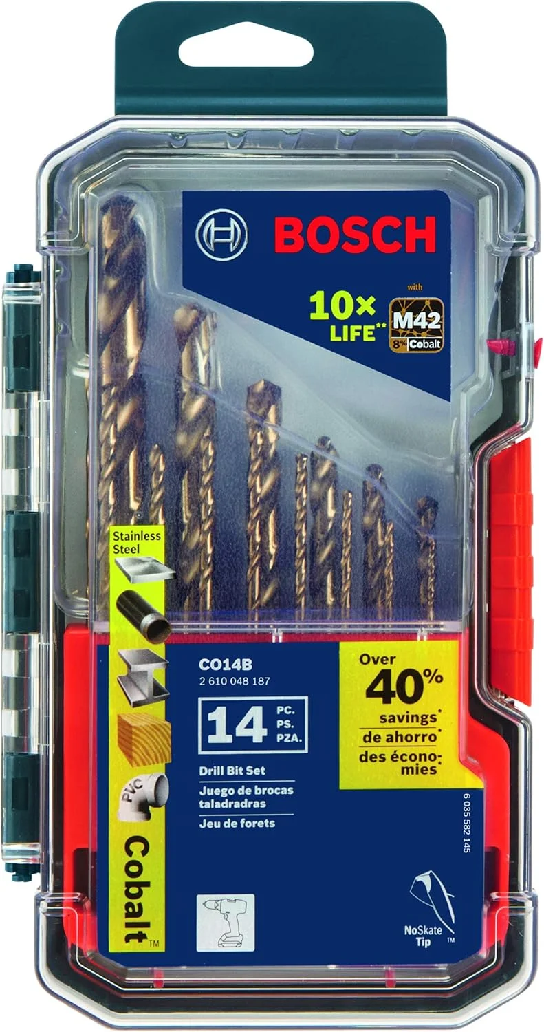
BOSCH CO14B 14-Piece Cobalt M42 Drill Bit Set
- Drilling / Machining — pilot holes before slotting
- Cobalt for tough alloys at entry
- Reduces corner-load spikes on end mills
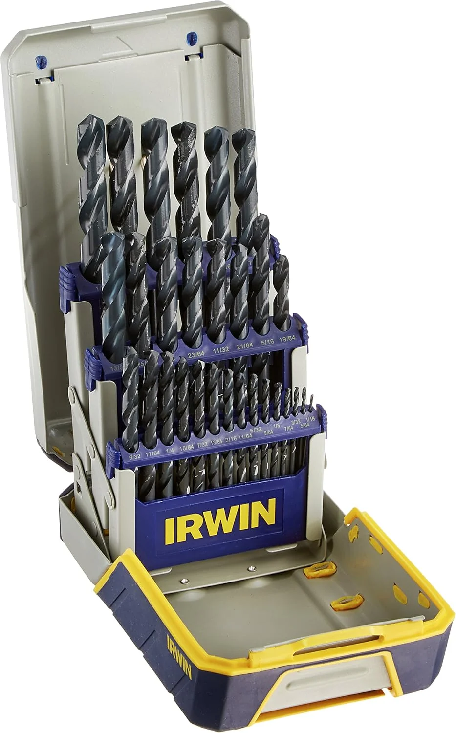
IRWIN 29-Piece Black Oxide Drill Bit Set
- Drilling / Machining — second catalog drill SKU
- Fractional & number coverage for layout
- Predrill before full-width end-mill slots

WD-40 Specialist Dry Lube Smart Straw
- Chip welding fix when IPT is already low
- Evacuates aluminum curls at the cut zone
- Shop Supplies — supports milling troubleshooting
As an Amazon Associate, TestTalkHQ earns from qualifying purchases. Drilling / Machining had only two drill-bit SKUs before the end-mill set was added — remaining cards use Measurement and Shop Supplies picks that support chip-load diagnosis.
Frequently Asked Questions
The calculator says my IPT is fine — why are chips welding?
Back-calculate from the actual programmed feed. Charts assume shearing; if flute count, RPM, or IPM drifted, real IPT can be far below the number you intended. Aluminum also needs flute clearance, not just IPT.
Why did a light radial cut break a tool at chart IPT?
Chip thinning: average chip thickness drops with light WOC. Without raising programmed IPT (or CAM compensation), the edge rubs then spikes. Or you applied peripheral IPT to a full slot — opposite error.
Can correct IPT still leave a bad finish?
Yes — flute geometry, runout, deflection, and dull edges control finish after IPT is “right.” Diagnose those before lowering feed into the rub zone.
Is this the same as the Chip Load Guide?
No. The guide teaches what IPT is, how to read charts, and general too-low/too-high symptoms. This page diagnoses failures when the calculation already looks correct.
Where do I pick climb vs conventional?
Use Climb vs Conventional Milling — that is the decision article for this calculator cluster.