Milling Speeds and Feeds Guide
SFM, RPM, chip load, and feed rate for every common material
Wrong speeds and feeds are the number one cause of broken end mills, bad surface finish, and scrapped parts. Every material has an optimal SFM range. Every cutter diameter converts that SFM to a specific RPM. Every operation has a chip load range that keeps the tool cutting instead of rubbing. This guide gives you the numbers for every common material and cutter combination — and explains the logic behind them so you can adapt when you're cutting something not on the chart. Use the Chip Load Calculator when you already have RPM and need feed from IPT, or the Milling Speed and Feed Rate Calculator for exact numbers on your specific setup.

The Three Numbers That Matter
Every milling operation is controlled by three variables: SFM (the speed of the cutting edge), RPM (the spindle speed that achieves that SFM for your cutter diameter), and feed rate (how fast the table moves in IPM). These three are not independent — they're all derived from two inputs: the recommended SFM for your material and cutter, and the chip load for your cutter size and material. Get SFM and chip load right and RPM and feed rate follow automatically.
The formula is straightforward: RPM = (SFM × 3.82) / cutter diameter in inches. Feed rate in IPM = RPM × number of flutes × chip load per tooth. Material removal rate = feed rate × width of cut × depth of cut. Start with the SFM table for your material, pick the midpoint, calculate RPM, set your chip load, calculate feed rate, and adjust from there based on what you hear and see.
Milling SFM by Material — Quick Reference
| Material | HSS SFM | Carbide SFM | Notes |
|---|---|---|---|
| Mild Steel | 50–80 | 200–400 | Cutting oil recommended |
| Tool Steel | 30–50 | 100–200 | Cutting oil required, slow down for hardened |
| Stainless Steel | 20–40 | 100–200 | Flood coolant required, low chip load |
| Cast Iron | 50–80 | 200–350 | Dry preferred, abrasive — watch tool wear |
| Aluminum | 200–400 | 600–1200 | Flood or WD-40, high chip load |
| Brass | 150–250 | 400–700 | Dry or light oil, watch for grab |
| Copper | 100–150 | 300–500 | Cutting oil, gummy material |
| Plastic | 200–400 | 400–800 | Dry or air blast only |
Carbide end mills can run 3–5× higher SFM than HSS in most materials. This is where CNC machining gets its productivity advantage — not just from automation but from the ability to run carbide tools at full speed without operator fatigue being a limiting factor. On a manual Bridgeport, you may not be able to achieve full carbide SFM if the spindle doesn't go high enough — especially on small diameter cutters in aluminum.
Always start at the lower end of the SFM range and work up. Signs you're running too fast: blue or black chips (steel), tool discoloration, burning smell, rapid tool wear. Signs you're running too slow: squeaking or chatter, built-up edge on the tool, poor surface finish with torn rather than sheared surface.
Chip Load Reference Table
Chip load (inches per tooth, IPT) is the thickness of the chip each flute takes per revolution. These values are for carbide 4-flute end mills in mild steel — see the scaling factors below for other materials.
| Cutter Diameter | Chip Load (IPT) | Feed Rate Example (4-flute, 500 RPM) |
|---|---|---|
| 1/8 in | 0.0005–0.001 | 1.0–2.0 IPM |
| 3/16 in | 0.001–0.0015 | 2.0–3.0 IPM |
| 1/4 in | 0.001–0.002 | 2.0–4.0 IPM |
| 3/8 in | 0.002–0.003 | 4.0–6.0 IPM |
| 1/2 in | 0.003–0.005 | 6.0–10.0 IPM |
| 3/4 in | 0.004–0.007 | 8.0–14.0 IPM |
| 1 in | 0.005–0.010 | 10.0–20.0 IPM |
Chip load scaling by material:
| Material | Chip Load Multiplier vs Steel |
|---|---|
| Aluminum | 2.0× |
| Brass | 1.5× |
| Cast Iron | 0.8× |
| Stainless Steel | 0.6× |
| Tool Steel | 0.7× |
| Plastic | 2.0× |
| Copper | 0.8× |
Correct chips tell you the parameters are right. In mild steel and tool steel, look for blue-gray or silver curled chips about the thickness of a fingernail — not powder, not long stringy birds nests. Aluminum should produce large, shiny curls that evacuate freely from the flutes — if chips weld to the tool, you're too slow or too hot. Stainless produces short, tight curls when chip load and coolant are correct; stringy or discolored chips mean work hardening is starting.
Bad chips are the warning sign before tool failure. Powder or dust in cast iron or steel means rubbing — increase feed or chip load. Long stringy chips in stainless or copper mean too much heat and too little chip load. Melted or re-welded chips on aluminum mean built-up edge — increase SFM and use coolant. Plastic that gums or melts means reduce RPM and use air blast to clear chips. Cast iron should produce fine gray powder — if you see sparks or smoke, slow down.
Mild Steel Milling — Speeds and Feeds
| Cutter Dia | Carbide RPM | HSS RPM | Feed Rate (4fl carbide) | Chip Load |
|---|---|---|---|---|
| 1/4 in | 3,820 | 955 | 15–30 IPM | 0.001–0.002 |
| 3/8 in | 2,547 | 637 | 20–40 IPM | 0.002–0.003 |
| 1/2 in | 1,910 | 477 | 23–48 IPM | 0.003–0.005 |
| 3/4 in | 1,273 | 318 | 20–36 IPM | 0.004–0.007 |
| 1 in | 955 | 239 | 19–38 IPM | 0.005–0.010 |
RPM calculated at 300 SFM carbide / 75 SFM HSS midpoint.
Aluminum Milling — Speeds and Feeds
Aluminum rewards aggressive parameters. Run high SFM, high chip load, flood coolant or WD-40, and keep chips clearing. The biggest risk is built-up edge — aluminum welds to the tool at low speeds and high heat.
| Cutter Dia | Carbide RPM | HSS RPM | Feed Rate (4fl carbide) | Chip Load |
|---|---|---|---|---|
| 1/4 in | 13,740 | 3,056 | 110–220 IPM | 0.002–0.004 |
| 3/8 in | 9,160 | 2,037 | 146–220 IPM | 0.004–0.006 |
| 1/2 in | 6,870 | 1,528 | 110–220 IPM | 0.004–0.008 |
| 3/4 in | 4,580 | 1,019 | 73–183 IPM | 0.004–0.010 |
| 1 in | 3,440 | 764 | 69–138 IPM | 0.005–0.010 |
RPM calculated at 900 SFM carbide / 200 SFM HSS midpoint.
Stainless Steel Milling — Speeds and Feeds
Stainless is the hardest material to mill correctly. Work hardening, heat buildup, and built-up edge all work against you. Low SFM, low chip load, flood coolant, and sharp carbide are non-negotiable. Never dwell — keep the cutter moving.
| Cutter Dia | Carbide RPM | HSS RPM | Feed Rate (4fl carbide) | Chip Load |
|---|---|---|---|---|
| 1/4 in | 2,293 | 458 | 5–9 IPM | 0.0006–0.001 |
| 3/8 in | 1,528 | 305 | 5–9 IPM | 0.0008–0.0015 |
| 1/2 in | 1,146 | 229 | 5–11 IPM | 0.001–0.0024 |
| 3/4 in | 764 | 153 | 4–11 IPM | 0.0014–0.0036 |
| 1 in | 573 | 115 | 3–9 IPM | 0.0015–0.004 |
RPM calculated at 150 SFM carbide / 30 SFM HSS midpoint.
Depth of Cut and Width of Cut Guidelines
Axial depth of cut (how deep the cutter goes into the material) and radial width of cut (how much of the cutter diameter is engaged) both affect tool load and heat. A general starting point for roughing: axial DOC = 1× cutter diameter, radial WOC = 50% of cutter diameter. For finishing: axial DOC = 0.5× diameter, radial WOC = 10–25% of diameter.
High-efficiency milling (HEM) strategies use a very small radial engagement (5–15% of diameter) with full axial depth. This keeps the chip thin and the tool cool, allowing much higher feed rates and longer tool life. Most modern CNC CAM software supports trochoidal or HEM toolpaths — if you're running production parts in steel or stainless on CNC, HEM is worth learning.
For exact numbers on your setup, use the Chip Load Calculator for IPT-to-feed math, or the Milling Speed and Feed Rate Calculator for full SFM/RPM/MRR. Read the Chip Load Guide for chart reading and troubleshooting. For failures when IPT already looks correct, see Chip Load Troubleshooting. Related tools: Climb vs Conventional Milling, Metal Cutting Speed Calculator, Drill Speed Calculator, and Drill Speeds by Material Chart.
⚡ Recommended Milling & Shop Tools
Cobalt drill sets, cutting fluid, and layout punches for milling setup and hole prep
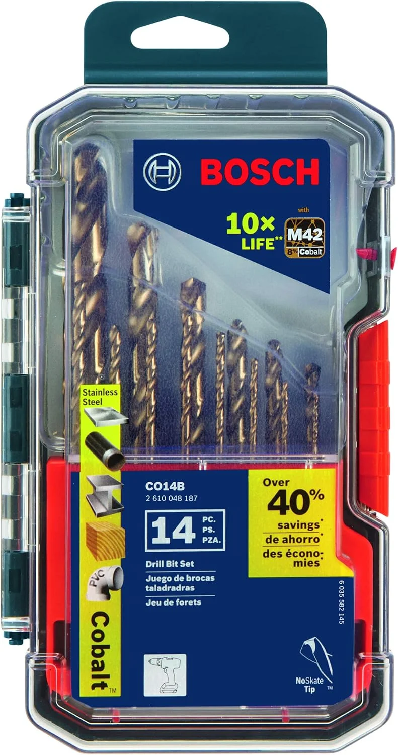
BOSCH CO14B 14-Piece Cobalt M42 Drill Bit Set
- Cobalt bits for tough alloys
- Hole prep before milling setups
- Three-flat shanks reduce slip
- Wide fractional coverage
- Shop staple for metalwork

Tap Magic Cutting Fluid
- Flood or apply at the cut zone
- Mandatory for aluminum milling
- Reduces heat on stainless
- Extends carbide tool life
- Shop standard for machining
Neiko Transfer Punch Set
- Transfer hole and layout marks
- Align workpieces on the mill
- Hardened punches for repeat use
- Essential for fixture setup
- Pairs with speed/feed planning
As an Amazon Associate, TestTalkHQ earns from qualifying purchases.
Why Your End Mills Keep Breaking
The four most common causes: too much radial engagement on the first pass (full slot milling with a worn or undersized end mill), running too slow in aluminum causing built-up edge and weld, running too fast in stainless causing work hardening, and poor workholding causing chatter that snaps carbide.
Carbide is hard but brittle — it doesn't flex, it snaps. Any vibration in the setup transfers directly to the tool. Fix workholding before changing speeds.
Number of Flutes — Does It Matter?
2-flute end mills have more chip clearance — they're ideal for aluminum where large chips need room to evacuate. 4-flute end mills are stiffer and produce better surface finish in steel but can clog in aluminum. 3-flute is a compromise that works well in both.
More flutes means higher potential feed rate (more teeth cutting per revolution) but less chip clearance. Match flute count to material: 2-flute for aluminum, 4-flute for steel and stainless, 3-flute for general purpose.
Cutting Fluid for Milling — What to Use and When
Flood coolant is ideal for production milling in steel and stainless — it removes heat, flushes chips, and extends tool life. For aluminum, WD-40 or a dedicated aluminum cutting fluid prevents built-up edge.
For cast iron, run dry — coolant causes thermal shock and actually reduces tool life on cast iron. For manual milling without flood coolant, a squeeze bottle of cutting oil applied at the cut zone works well for steel. Never use water-based coolant on cast iron or it will rust the workpiece and machine.
Surface Finish in Milling — How to Get It Right
Surface finish in milling is controlled by four factors: feed per tooth (lower chip load = better finish), cutter condition (sharp tools cut clean, dull tools rub and tear), radial runout (tool wobble creates scallops), and vibration (chatter leaves patterns on the surface).
For finishing passes, reduce chip load to 50% of roughing values, increase RPM 10–15%, and take a light radial cut. A sharp 4-flute carbide end mill at correct chip load should leave a finish that needs minimal hand work.