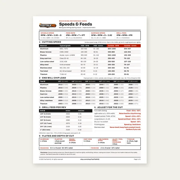
Machining Speeds & Feeds Card
One page. Speeds, chip load and drill feed, imperial and metric.
$3.99
BuySFM, RPM, chip load, and feed rate — how they connect, how to calculate them, and how to adjust when things go wrong.
RPM tells you how fast the spindle spins. SFM tells you how fast the cutting edge moves through the material. Start with the right surface speed for your material, convert to RPM for your tool diameter, then calculate feed rate from chip load.
Use the Chip Load Calculator for IPT-to-feed math, the Cutting Speed & Feed Rate Calculator for instant RPM and IPM, or work through the full guide below.

RPM tells you how fast your spindle is spinning. SFM tells you how fast the cutting edge is moving through the material. Those are not the same thing, and confusing them is one of the most common ways machinists wreck tools and workpieces.
Surface feet per minute (SFM) — also called surface speed or cutting speed — measures the velocity of the tool's cutting edge relative to the workpiece, expressed in feet per minute. It describes the physics of the cut: how much heat is generated, how quickly the tool wears, and whether the chip is forming correctly. Every material has an optimal SFM range based on its hardness, thermal conductivity, and abrasiveness. Run too fast and you burn the tool. Run too slow and you rub instead of cut, work-hardening the surface and still wearing the tool.
RPM, by contrast, is machine-dependent. A 1/4" end mill at 10,000 RPM and a 2" face mill at 10,000 RPM are doing completely different things at the cutting edge. The 1/4" tool has a tiny circumference, so its cutting edge barely moves per revolution. The 2" tool covers far more surface distance in the same revolution. That's why SFM — not RPM — is the fundamental parameter you work from when selecting speeds. You start with the recommended SFM for the material, then calculate the RPM your machine needs to run in order to achieve that SFM with the specific tool diameter you're using.
The conversion formula is straightforward:
RPM = (SFM × 3.82) ÷ Tool Diameter (inches)
The constant 3.82 comes from 12 ÷ π (12 converts feet to inches; π relates diameter to circumference). Some machinists use the approximation 12/π ≈ 3.82 directly. A few use 4 as a quick mental math shortcut — close enough for roughing estimates.
The exact derivation: Surface speed = circumference × RPM. Circumference = π × D (in inches) ÷ 12 (to convert to feet). So SFM = (π × D × RPM) ÷ 12. Solving for RPM: RPM = (SFM × 12) ÷ (π × D) = (SFM × 3.82) ÷ D.
Target SFM for aluminum (carbide): 500 SFM. Tool diameter: 0.500".
RPM = (500 × 3.82) ÷ 0.500 = 1,910 ÷ 0.500 = 3,820 RPM
Target SFM for mild steel (carbide): 100 SFM. Tool diameter: 0.750".
RPM = (100 × 3.82) ÷ 0.750 = 382 ÷ 0.750 = 509 RPM
Target SFM for stainless (carbide): 60 SFM. Tool diameter: 0.250".
RPM = (60 × 3.82) ÷ 0.250 = 229.2 ÷ 0.250 = 917 RPM
Notice how small-diameter tools require very high RPM to reach the same SFM as larger tools. This is why high-speed spindles (10,000–24,000 RPM) exist — they're necessary to correctly machine small-diameter cutters in softer materials. If your machine tops out at 4,000 RPM and you're running a 1/8" carbide end mill in aluminum (theoretical RPM: ~15,000+), you're severely underperforming the tool. Use the Cutting Speed & Feed Rate Calculator to instantly compute RPM and feed rate for any combination of material, tool diameter, and operation.
Once you have RPM, feed rate follows from three inputs: RPM, number of flutes on the cutter, and chip load (also called feed per tooth).
Feed Rate (IPM) = RPM × Number of Flutes × Chip Load (inches per tooth)
Chip load is the thickness of material each cutting edge removes per revolution. Too low a chip load produces rubbing and built-up edge. Too high produces chatter, deflection, and broken tools. Chip load values come from tooling manufacturers and vary by tool diameter and material — generally ranging from 0.0005" per tooth for small cutters in hard materials to 0.010"+ per tooth for large cutters in aluminum.
RPM: 3,820. Flutes: 3. Chip load: 0.004" per tooth (typical for a 1/2" carbide end mill in aluminum).
Feed Rate = 3,820 × 3 × 0.004 = 45.8 IPM
RPM: 509. Flutes: 4. Chip load: 0.002" per tooth.
Feed Rate = 509 × 4 × 0.002 = 4.1 IPM
Feed rate directly controls chip thickness, tool loading, and cycle time. Increasing feed rate improves productivity and chip formation as long as the tool and machine can handle the load. Decreasing it beyond a minimum threshold causes rubbing — the edge drags rather than cuts, generating heat without removing material efficiently.
These ranges apply to carbide tooling under normal machining conditions with adequate coolant or lubrication. Adjust downward for HSS, upward for ceramic or CBN where applicable. The lower end of each range suits roughing or interrupted cuts; the upper end suits finishing with light depths of cut.
Aluminum machines fast. Its low hardness and good thermal conductivity allow aggressive surface speeds. Most aluminum alloys run comfortably at 400–500 SFM with carbide. Higher SFM produces better surface finish and reduces built-up edge on the tool. Flood coolant or mist helps evacuate chips and prevents re-cutting. Alloys like 7075 sit toward the lower end versus easier-cutting 6061. Cast aluminum varies by silicon content — high-silicon alloys (like 380 casting alloy) are more abrasive and require lower SFM, closer to 200–350 SFM with uncoated carbide.
Low-carbon steel (1018, A36) runs at moderate speeds. Carbide holds up well across this range. At the upper end (110–120 SFM), you'll see faster tool wear if coolant is inadequate. At 80–90 SFM, roughing passes with heavy chip loads are more stable. Medium-carbon steels (1045, 4140 annealed) fall near 80–100 SFM. Pre-hardened steels drop further — treat them like stainless or hardened steel and reduce SFM accordingly.
Stainless is the problem child of common materials. It work-hardens instantly if you rub it — which happens when SFM is too low, chip load is too light, or you dwell in the cut. The solution is to keep the tool moving, maintain chip load, and stay in the 50–80 SFM range with sharp carbide. 304 stainless sits at 60–75 SFM. 316 runs a bit slower due to higher molybdenum content. Duplex and precipitation-hardened grades (17-4 PH) push down to 40–60 SFM. Always use flood coolant. Never let a stainless tool rub.
Gray cast iron cuts dry — it's self-lubricating due to graphite flake content. Coolant can cause thermal shock and cracking in some cast irons, so dry cutting or air blast is common. SFM range of 70–100 SFM works for most gray iron with carbide. Ductile (nodular) iron is tougher and sits at 60–80 SFM. White cast iron is extremely hard and abrasive; ceramic or CBN tooling is preferred and speeds vary by tooling manufacturer recommendation.
Titanium is slow for two reasons: it's strong, and it's a terrible conductor of heat. Heat generated in the cut stays in the tool instead of transferring into the chip or workpiece. At SFM above 50 with carbide, tool life collapses rapidly. Run at 30–50 SFM with sharp, uncoated or TiAlN-coated carbide, high chip load (to force heat into the chip), flood coolant at high pressure, and never stop feeding mid-cut. Titanium will work-harden almost as aggressively as stainless if you rub it. Grades like Ti-6Al-4V (Grade 5) are the most common in machining and sit firmly at 30–45 SFM with carbide.
Free-machining brass (360 brass) is one of the easiest materials to cut. It produces short, clean chips and tolerates high SFM. 200–250 SFM with carbide is common for finishing. Bronze alloys vary considerably — bearing bronzes with lead additions machine similarly to brass. Silicon bronze and aluminum bronze are tougher and sit closer to 100–150 SFM. Most brass work is done without coolant or with a light mist.
For a quick reference that also handles turning, drilling, and threading operations, use the Metal Cutting Speed Calculator to cross-check your SFM-to-RPM conversions against material-specific recommendations.
The recommended SFM isn't a single number — it's a range, and where you sit in that range depends on what the cut is doing.
Roughing: Use the lower end of the SFM range. Roughing involves larger depths of cut, higher chip loads, and more tool engagement. The goal is material removal rate, not surface finish. Running slower SFM with aggressive feed rates keeps tool temperatures manageable and reduces chatter. For heavy slotting (full-width engagement), drop SFM by 20–30% compared to peripheral milling.
Finishing: Use the upper end of the SFM range, reduce depth of cut, reduce chip load slightly, and prioritize surface finish over removal rate. Higher SFM on finishing passes improves surface speed relative to tool deflection and can produce a better finish. In aluminum especially, pushing SFM high on finishing passes reduces built-up edge and gives a near-polished result.
Drilling: SFM in drilling is calculated at the drill's outer diameter, same formula. Common SFM for drilling mild steel: 60–80 SFM with HSS, 80–120 SFM with carbide. Peck cycles become critical in deeper holes to evacuate chips.
Tapping: Use 20–40% of the recommended milling SFM for the material. Tapping is a constrained operation — the tool can't deflect, and any overload breaks the tap. Slower is almost always safer.
Turning (lathe): The same SFM formula applies, but diameter is the workpiece diameter, not tool diameter, and it changes as the part gets smaller. CNC lathes with constant surface speed (CSS) mode automatically vary RPM to maintain SFM as diameter decreases — a critical feature for facing operations.
Tool material is not a secondary consideration. It's one of the primary inputs to SFM selection because different tool materials handle heat, hardness, and abrasion resistance in fundamentally different ways.
High Speed Steel (HSS): Run at 30–50% of carbide SFM recommendations. HSS softens at around 1,000°F, so heat is its enemy. It's tougher than carbide (more resistant to chipping on interrupted cuts) and significantly cheaper. Good for low-volume work, manual machines with limited RPM, or when workpiece hardness is low. HSS spiral taps and drills remain common even in CNC shops because of their toughness and cost.
Cobalt HSS (M35, M42): Slightly higher heat resistance than standard HSS. Run at 10–15% higher SFM than standard HSS. Useful for stainless and high-temperature alloys where standard HSS wears too fast but carbide is overkill or too brittle for the setup.
Carbide (uncoated): The baseline for modern machining. Stays hard up to roughly 1,400°F. Run at the SFM ranges listed above. Uncoated carbide is preferred for aluminum and non-ferrous materials where coatings can cause built-up edge. C2/K10 grade for non-ferrous, C6/P30 equivalent for steel.
Coated Carbide (TiN, TiCN, TiAlN, AlTiN): Coatings add hardness, reduce friction, and increase heat resistance. TiAlN and AlTiN coatings allow 20–30% higher SFM in steels compared to uncoated carbide, particularly in dry or minimum quantity lubrication (MQL) machining. AlTiN is preferred for hardened steels and high-temperature alloys. Do not use TiN-coated tools in aluminum — the coating has an affinity for aluminum and promotes built-up edge.
Ceramic: Run at 3–10× the SFM of carbide, primarily for hardened steels and cast iron. Ceramic is brittle and cannot handle interrupted cuts or coolant (thermal shock). Dry cutting only. SFM for ceramic in hardened steel: 800–1,500 SFM. Requires rigid setups and high-speed spindles.
CBN (Cubic Boron Nitride): Used for hardened steels above 45 HRC. SFM: 300–800 SFM depending on hardness. CBN inserts replace grinding in many hard-turning operations and produce excellent surface finish on hardened bores and shafts.
The machine tells you when the parameters are wrong. Learn to read the signs rather than waiting for tool failure.
Running too fast: Tool heat is the primary indicator. A blue or discolored cutting edge after a pass means the tool exceeded its thermal limit. Chips that are blue, purple, or black indicate excessive cutting temperature (common in steel). Rapid tool wear — needing to change inserts or end mills after short run times — points to overspeed. In aluminum, a gummy buildup on the cutting edge (built-up edge) can indicate excessive heat despite the lower SFM range. Surface finish that looks burnished or smeared rather than cut is another indicator.
Running too slow: Chatter and vibration from rubbing rather than cutting. Work hardening on the surface of stainless or titanium — visible as a glazed, hard skin that makes subsequent passes even harder to cut. Poor chip formation: instead of clean, curled chips, you see powder or fine dust (common in rubbing scenarios). The sound changes — a cutting tool should produce a consistent hiss or hum; rubbing produces squealing or chatter. Tool wear still occurs because rubbing generates abrasive friction even without proper chip formation.
Feed rate too low (even at correct RPM): Thin, wispy chips. Heat stays in the tool rather than leaving with the chip. Surface finish may look better momentarily but tool life suffers. This is a common mistake on manual machines where operators slow down to "be safe" — they're actually increasing tool wear by reducing chip thickness.
Feed rate too high: Chatter, deflection, rough surface finish, tool breakage. The machine sounds labored. Chip evacuation becomes a problem — chips pack the flutes and re-cut, which damages both the tool and workpiece.
Most manual mills and lathes have fixed speed steps. CNC machines have a maximum RPM that may be insufficient for small-diameter tools. Here's how to work within those constraints.
When you can't go fast enough: Use a larger tool diameter if the geometry allows. A larger tool reaches target SFM at lower RPM. Alternatively, switch to a different operation — instead of a 1/8" end mill in aluminum at 15,000 RPM (which you don't have), rough with a 3/8" end mill at a manageable RPM and finish with a smaller pass. If the application demands a small tool, consider a high-speed spindle attachment.
When you can't go slow enough: This is rare on modern machines but common on older variable-speed mills. If your minimum RPM is still too high for the target SFM, switch to HSS tooling. Its lower SFM recommendation brings the math back into range. A 1" HSS face mill in mild steel targets 80 SFM (HSS) → RPM = (80 × 3.82) ÷ 1.0 = 306 RPM, more achievable on a Bridgeport-style machine than a carbide target of 120 SFM → 458 RPM.
Close enough is usually fine: SFM recommendations are ranges, not precise values. If your machine steps from 400 to 550 RPM and the calculation says 480 RPM, run 400 and adjust feed rate proportionally. Tool life may suffer slightly, but you won't destroy the tool. What matters more is staying within the SFM range for the material — being 10% off is manageable; being 200% off is not.
Reduce depth of cut instead: If running lower than ideal SFM due to machine limits, compensate by reducing depth of cut and radial engagement. Less material contact per revolution reduces heat and tool load at the lower speed. It trades cycle time for tool life and setup capability.
No. SFM (surface feet per minute) measures cutting edge velocity — how fast the tool contacts the workpiece. IPM (inches per minute) is feed rate — how fast the tool traverses across the workpiece. They're related through RPM: feed rate (IPM) = RPM × flutes × chip load. SFM drives RPM selection; IPM is calculated after RPM is determined. Both matter, but SFM comes first in the calculation chain.
Yes, significantly. Flood coolant allows 10–30% higher SFM in most ferrous materials by removing heat from the cutting zone. Dry machining requires reducing SFM to keep tool temperatures within limits — especially with uncoated carbide. Exception: cast iron and some ceramics should be cut dry because coolant causes thermal shock. For stainless and titanium, flood coolant is not optional — dry cutting these materials at even correct SFM leads to rapid tool failure.
RPM alone doesn't prevent breakage — feed rate, depth of cut, and radial engagement all contribute to tool load. The most common cause of end mill breakage (outside of crashes) is too low a feed rate combined with full slotting. Reducing chip load below the minimum causes the tool to rub, flex, and fatigue. Ensure you're running appropriate chip load for the tool diameter and material, and avoid full-width slotting passes unless the tool is specifically designed for it. Also check for runout — as little as 0.001" of runout on a 1/8" end mill can double the effective chip load on one flute and snap the tool.
Use diameter-based rules of thumb as a starting point. For end mills in steel, chip load typically falls between 0.5–1% of tool diameter per tooth. For aluminum, 1–2% of tool diameter per tooth. A 1/2" end mill in steel: start at 0.003–0.005" per tooth. A 1/2" end mill in aluminum: start at 0.004–0.008" per tooth. Adjust by listening: too light sounds like rubbing or squealing; correct sounds like a steady, firm cut with clean chip ejection. When in doubt, run conservatively and increase feed rate in 10% increments until cut quality, sound, and chip color confirm you're in range.
One page. Speeds, chip load and drill feed, imperial and metric.
$3.99
Buy
27 pages. Milling, drilling, tapping, turning and CNC routing.
$12.99
Buy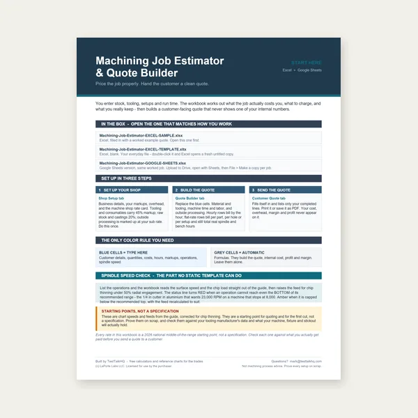
Quote shop work and check operations against your spindle's top speed.
Excel or Google Sheets. Best on a computer.
$29.00
Buy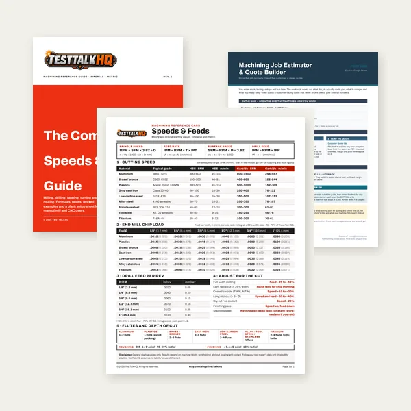
Card, 27-page guide and the estimator workbook. All six files.
Excel or Google Sheets. Best on a computer.
$34.99
$45.98 if bought separately — save $10.99
BuyCheckout opens in a new tab.
Measure tool diameter accurately, keep cutting zones cool, and protect toolholder threads

Measuring actual tool diameter before calculating RPM eliminates the errors that come from assuming nominal size. End mills and drills can vary from nominal by a few thousandths — enough to matter on precise speed calculations. The Starrett EC799A reads to 0.0005 inch and is the caliper serious machinists trust for tool and workpiece measurement.
Check Price
Running at correct SFM without cutting fluid in steel and stainless still produces built-up edge and poor surface finish. Tap Magic applied to the cutting zone reduces heat, prevents BUE, and extends tool life measurably in turning, milling, drilling, and tapping operations. The difference in tool life between dry and wet cutting in steel is not subtle.
Check Price
Anti-seize on toolholder threads, collet nuts, and arbor connections prevents galling and makes tool changes faster and cleaner. On any threaded connection that gets tightened repeatedly in a machine tool environment, anti-seize is standard maintenance practice that extends the life of toolholders and spindle components.
Check PriceAs an Amazon Associate, TestTalkHQ earns from qualifying purchases.
Most machinists set RPM directly on their machine and think in RPM terms. The problem is that RPM is only meaningful relative to tool diameter — 1,000 RPM on a 1-inch end mill is completely different from 1,000 RPM on a 1/4-inch end mill. SFM is the universal constant: the speed at which the cutting edge moves through material, regardless of tool size. Published cutting data is almost always given in SFM because it applies to any tool diameter once you convert. Once you understand the SFM-to-RPM conversion, you can work from any cutting data table and arrive at the correct spindle speed for whatever tool you have in the machine. RPM is the output; SFM is the input.
Running too fast shows up quickly: blue chips in steel, rapid tool wear, poor surface finish, and in severe cases, tool failure. The cutting edge overheats, loses hardness, and stops cutting — it starts rubbing instead, which accelerates heat and wear in a feedback loop. Running too slow is less dramatic but equally destructive over time: thick, heavy chips that overload the cutting edge, poor chip evacuation, excessive cutting forces, and deflection. In drilling, running too slow with too much feed pressure causes drill wander and oversized holes. The correct SFM range puts you in the window where the tool cuts cleanly, chips evacuate properly, and tool life is maximized. Outside that window in either direction, you’re spending money on tools faster than necessary.
Manual lathes and older mills often have fixed spindle speeds in steps rather than continuous variable control. When your calculated RPM falls between two available speeds, always choose the lower one — running slower than optimal costs you some productivity but doesn’t damage the tool. Running faster than optimal costs you tool life and surface finish. On a lathe with speeds of 300 and 450 RPM where the calculation says 380, use 300. The 20% reduction in surface speed reduces productivity slightly and has minimal effect on tool life. The alternative — running 18% fast at 450 — visibly shortens tool life in harder materials. Know your machine’s speed steps and build a reference card of what SFM each step produces at your most common tool diameters.
High-speed steel (HSS) and carbide are not interchangeable at the same cutting speeds. Carbide maintains its hardness at temperatures that would soften HSS immediately, which means carbide can run at 3 to 5 times the SFM of HSS in the same material. An operation running mild steel at 100 SFM with HSS can run at 300-400 SFM with carbide inserts or solid carbide end mills. The higher speed means faster material removal, better surface finish in many cases, and longer tool life — but only if the machine is rigid enough to handle the increased cutting forces without chatter. Carbide at high SFM on a loose or worn machine produces chatter and tool breakage. The tool material upgrade has to match the machine capability or you get the worst of both worlds.
Cutting Speed Troubleshooting for symptom diagnosis when SFM looks correct. Carbide vs HSS Tooling for tool-material decisions that change the speed window.