
Welding Reference Card
One page. MIG, TIG, stick and flux core settings by thickness.
$3.99
BuyAmperage, Air Pressure & Speed for Every Material
The complete reference for dialing in your plasma cutter on mild steel, stainless, and aluminum — from gauge sheet to 1-inch plate.
Every plasma cut is controlled by five variables working together. Change one without accounting for the others and your cut quality falls apart.
Amperage is your primary power setting. Higher amperage means more heat at the arc, which lets you cut thicker material or move faster through thinner material. The rule of thumb: run the highest amperage your consumables support for the thickness you're cutting, then dial in speed to match. Underpowering a thick cut forces you to slow down so much that dross builds up and the kerf gets sloppy.
Cutting speed (IPM) has the largest effect on cut quality of any variable you control in real time. Too fast and you get top-of-kerf spatter and an incomplete arc blow-through. Too slow and molten metal re-solidifies as hard bottom dross. The correct speed produces a clean exit arc that trails 5–15° behind vertical on the bottom of the cut — you can see this by watching the arc exit angle from the back side of the material.
Air pressure both sustains the plasma arc and blows the molten metal out of the kerf. Too low and the arc is weak and unstable. Too high and you cool the arc excessively, causing a rough, striated cut face. Pressure requirements scale with amperage — a 40A machine needs around 60–65 PSI; an 80A machine needs 70–80 PSI. CFM (volume) matters as much as PSI: a compressor that can't sustain the required flow will cause pressure sag mid-cut, which shows up as an irregular cut edge.
Standoff distance is the gap between the tip of the torch and the workpiece surface. Most handheld cutting uses a drag shield at zero standoff. When running without a drag shield, maintain 1/8" (3mm) for general cutting. Increase standoff on piercing to protect the tip from blowback. On CNC tables, standoff is typically 0.06"–0.12" and is controlled by an arc voltage height controller (THC).
Consumable condition is the variable most operators overlook. A worn electrode or enlarged tip orifice will degrade cut quality faster than any settings adjustment can compensate for. Inspect before every job and replace on schedule — not when the arc finally goes out.
Mild steel (A36, 1018, hot-rolled) is the most forgiving plasma cutting material. These settings apply to standard air plasma with a properly filtered, dry air supply.
| Thickness | Amperage | Air Pressure (PSI) | Cut Speed (IPM) | Standoff |
|---|---|---|---|---|
| 16 ga (0.060") | 20–30A | 55–60 PSI | 150–200 IPM | 1/16" |
| 14 ga (0.075") | 30–40A | 58–62 PSI | 120–160 IPM | 1/16" |
| 10 ga (0.135") | 40A | 60–65 PSI | 80–100 IPM | 1/8" |
| 3/16" (0.188") | 40–50A | 62–68 PSI | 45–65 IPM | 1/8" |
| 1/4" (0.250") | 60A | 65–70 PSI | 55–75 IPM | 1/8" |
| 3/8" (0.375") | 60–80A | 68–75 PSI | 30–45 IPM | 1/8" |
| 1/2" (0.500") | 80A | 70–78 PSI | 22–35 IPM | 1/8"–3/16" |
| 3/4" (0.750") | 80–100A | 75–80 PSI | 12–18 IPM | 3/16" |
| 1" (1.000") | 100A+ | 78–85 PSI | 8–12 IPM | 3/16" |
Stainless cuts at roughly 80–90% of the speed you'd use on mild steel of the same thickness at the same amperage. The cut face will have a blue heat-affected oxide zone — that is normal. If you need a bright, oxidation-free edge, switch to nitrogen as your plasma gas, though that requires a machine that supports alternative gases. With air plasma, reduce speed slightly versus mild steel and keep air pressure on the lower end of the range to minimize edge oxidation.
| Thickness | Amperage | Air Pressure (PSI) | Cut Speed (IPM) | Standoff |
|---|---|---|---|---|
| 16 ga (0.060") | 20–30A | 55–60 PSI | 120–160 IPM | 1/16" |
| 10 ga (0.135") | 40A | 60–65 PSI | 60–80 IPM | 1/8" |
| 1/4" (0.250") | 60A | 65–70 PSI | 40–55 IPM | 1/8" |
| 3/8" (0.375") | 80A | 70–75 PSI | 25–35 IPM | 1/8" |
| 1/2" (0.500") | 80A | 72–78 PSI | 14–20 IPM | 3/16" |
| 3/4" (0.750") | 100A | 75–82 PSI | 8–13 IPM | 3/16" |
Aluminum cuts faster than mild steel in thin gauges — the material melts and ejects cleanly because aluminum's low melting point means the arc doesn't have to work as hard. As thickness increases, aluminum becomes comparatively more demanding because it conducts heat away from the arc rapidly. Use higher amperage than you'd expect for the thickness. Aluminum also produces a rougher oxide layer on the cut edge than mild steel; a slightly higher air pressure helps blow it clear. Keep the torch moving — dwelling on aluminum scorches and warps the material quickly.
| Thickness | Amperage | Air Pressure (PSI) | Cut Speed (IPM) | Standoff |
|---|---|---|---|---|
| 1/8" (0.125") | 40A | 62–68 PSI | 150–200 IPM | 1/16"–1/8" |
| 3/16" (0.188") | 40–50A | 65–70 PSI | 100–140 IPM | 1/8" |
| 1/4" (0.250") | 60A | 68–72 PSI | 80–100 IPM | 1/8" |
| 3/8" (0.375") | 80A | 70–76 PSI | 40–60 IPM | 1/8" |
| 1/2" (0.500") | 80A | 72–78 PSI | 20–30 IPM | 3/16" |
| 3/4" (0.750") | 100A | 75–82 PSI | 10–16 IPM | 3/16" |
These are at-the-machine requirements — the pressure the regulator on your plasma cutter should read under load, not the tank or compressor output pressure. Set your compressor to deliver at least 20–25 PSI above these values so the regulator has headroom to maintain pressure during a long cut. A compressor that cannot sustain CFM will cause pressure sag, which shows up as a wandering arc and rough cut face. Most machines in the 60–80A range require a compressor rated for at least 6–8 SCFM at 90 PSI — check this against your compressor's spec plate, not the horsepower rating.
| Amperage Range | Required PSI (at machine) | Required CFM (SCFM) | Minimum Compressor |
|---|---|---|---|
| 20–30A | 55–65 PSI | 3.5–4.5 SCFM | 2–3 HP, 20-gal tank |
| 30–50A | 60–70 PSI | 4.5–6.0 SCFM | 3–5 HP, 30-gal tank |
| 50–70A | 65–75 PSI | 6.0–7.5 SCFM | 5 HP, 60-gal tank |
| 70–100A | 70–85 PSI | 7.5–10 SCFM | 5–7.5 HP, 80-gal tank |
| 100A+ | 80–95 PSI | 10–15 SCFM | 7.5–10 HP, 120-gal tank |
Moisture in the air supply destroys consumables and ruins cut quality. If you don't already have a desiccant dryer and coalescing filter inline between the compressor and the plasma cutter, install one. A wet air supply is the most common cause of premature electrode failure and erratic arc behavior in shop environments.
The dross left on a cut tells you exactly what went wrong before you make another pass.
Top spatter (top dross): Fine metallic spray on the top surface of the cut, sometimes fine enough to look like roughened paint. This means you are moving too fast for the amperage — the arc is not penetrating fully and the molten metal is being splashed back up. Fix: slow down or increase amperage. If you can't slow down (thin material warping), increase amperage first.
Bottom dross (slag): Globby, rounded beads of re-solidified metal stuck to the bottom edge of the cut. This is the most common dross type. It means the cut speed is too slow — the molten metal is dwelling in the kerf long enough to re-solidify before the air blast clears it. Fix: increase speed. Bottom dross from a slightly slow cut is relatively easy to knock off with a chipping hammer; bottom dross from a very slow cut welds itself to the edge and requires grinding.
Hard, fine bottom dross: A thin, flat fin of hard material bonded tightly along the entire bottom edge — harder to remove than standard bottom dross. This is high-speed dross caused by excessive speed combined with higher amperage. The arc is blowing through, but the swirl of the plasma gas is pushing the resolidified material to the bottom edge at an angle. Fix: reduce speed slightly and verify your air pressure isn't over the recommended PSI for your amperage.
The trailing arc angle check: Watch the arc exit from the bottom of the material as you cut. At correct speed, the arc trails 5–15° behind the torch direction. If the arc exits straight down (0°), you're moving too slow. If it trails more than 20–25° behind, you're moving too fast and the arc may not be fully penetrating.
Running worn consumables is the single most expensive mistake in plasma cutting. A $6 electrode that should have been changed an hour ago can produce $200 worth of bad cuts and potentially damage the torch body.
Electrode: Inspect the hafnium insert at the center of the electrode face. When the pit depth exceeds 1/16" (approximately 1.5mm), replace the electrode. Do not try to gauge this by eye — use a straightedge across the face and a feeler gauge, or compare to a new electrode. A pitted electrode causes a wandering, unstable arc that produces a wavy cut edge. On high-amperage machines or in high-production environments, change electrodes on a start-count schedule (typically every 500–800 starts) rather than waiting for visible wear.
Tip (nozzle): Inspect the orifice. It should be round and have clean, sharp edges. Replace the tip when the orifice is enlarged, oval, or shows pitting around the opening. An enlarged orifice reduces arc constriction, which widens the kerf and degrades cut squareness. Tips and electrodes wear together — change them as a pair. Replacing only one extends neither.
Swirl ring and shield: Inspect the swirl ring every two to three tip changes. Clogged swirl ring holes kill gas flow balance and cause the arc to wander. The shield cap takes blowback spatter on piercing — inspect it for blockage of the airflow holes and replace when it is heavily pitted or blocked.
For quick reference on settings for a specific thickness and material, use the TestTalkHQ Plasma Cutting Calculator or pull up the Plasma Cutting Settings Chart.
Rough or striated cut face: Usually caused by incorrect speed (most often too slow), worn consumables, or contaminated air supply. Check consumables first — this takes thirty seconds and eliminates the most common cause. If consumables are good, increase cut speed in 5–10 IPM increments until the face smooths out. If the problem persists at correct speed and with fresh consumables, install or replace the air dryer and filter.
Excessive bevel angle on cut edge: A small bevel (1–3°) is normal for plasma cutting — the kerf is slightly wider at the top than the bottom due to arc geometry. Bevel beyond 3–5° indicates torch tip angle (the torch is not perpendicular to the work), excessive standoff distance, or a worn tip allowing the arc to spread. Verify your torch is truly 90° to the material and reduce standoff. On CNC tables, bevel can also indicate incorrect cut direction relative to the swirl of the plasma gas — consult your machine manufacturer for the preferred cut direction.
Arc going out mid-cut: The arc extinguished and restarted, leaving a notch or restart mark in the cut. Most common causes: the cut speed was too fast and the arc blew out at a thick section; air pressure dropped (compressor can't maintain CFM); or the pilot arc timer on the machine timed out before the arc transferred to the work (typically on rusty or painted material). Check your compressor's actual sustained output, clean the material surface at the start point, and reduce speed if cutting variable-thickness plate.
Piercing blowback: Molten metal ejected upward from the pierce point that strikes and damages the tip. Blowback is the primary cause of premature tip failure on handheld work. Fix: pierce at the edge of the material whenever possible rather than in the center. When you must pierce in the middle, tilt the torch 30–45° at the start, let the pierce complete, then bring the torch to vertical and begin the cut. On thicker material (¼" and above), increase standoff distance to 3/8"–1/2" for the pierce, then return to normal standoff for the cut. Some machines have a pierce mode or pierce delay — use it.
For specific settings dialed to your exact thickness and material, use the TestTalkHQ Plasma Cutting Calculator to get amperage, speed, and pressure in one lookup. The Plasma Cutting Settings Chart covers a wider range of machines and materials in a printable format.
Comparing thermal processes? Use the Oxy-Fuel Cutting Tip Calculator, Oxy-Fuel Cutting Guide, Oxy-Fuel Troubleshooting, and Oxy-Fuel vs Plasma.
When settings matched the tables but cuts still failed, see Plasma Cutting Troubleshooting.
Gantry and CNC table operators should not copy these handheld amps and travel speeds into CAM. Use the CNC Plasma Pierce Height & Cut Speed Calculator for programmed pierce height, delay, cut height, and an IPM starting range, then coupon the nest. Dial-in order: CNC plasma guide.
PSI depends on your amperage setting. For machines in the 40–60A range, set the at-machine pressure to 60–70 PSI. For 60–80A, use 65–78 PSI. For 80–100A, 72–85 PSI. These are the pressures your machine's regulator should read under load — not the compressor tank pressure. Your compressor should deliver at least 20–25 PSI above these values so the regulator can maintain steady pressure during a long cut. Always verify with the specific spec sheet for your machine model, as recommended pressure varies between manufacturers.
Bottom dross (slag beads on the underside of the cut) is almost always caused by cutting too slowly for your amperage. The molten metal is dwelling in the kerf long enough to resolidify before the air blast can clear it. Increase your cut speed in 5–10 IPM increments until the dross disappears or becomes easy to knock off. If you are already at the top of the recommended speed range and still getting bottom dross, increase your amperage. Worn consumables can also cause dross even at correct settings — replace the tip and electrode and retest before chasing a speed adjustment.
Replace the electrode when the hafnium insert pit at the center of the electrode face exceeds 1/16" (1.5mm) deep — measure with a straightedge and feeler gauge rather than guessing by eye. Replace the tip (nozzle) when the orifice is no longer round, is visibly enlarged, or shows pitting around the opening. Change tips and electrodes together as a pair, since they wear at similar rates and replacing only one wastes the remaining life of the other. In production cutting, track by start count and change on schedule (every 500–800 starts is common) rather than waiting for visible failure.
Three main causes: (1) The cut speed is too fast and the arc lost transfer — slow down and ensure the arc has fully transferred to the work before moving. (2) Air pressure dropped mid-cut because the compressor can't sustain the required CFM — check your compressor's rated SCFM at the required PSI and compare it to your machine's air consumption spec. A tank that runs out mid-cut or a compressor that undersizes for your amperage will cause this. (3) Contaminated or painted material caused the arc to lose transfer at the start — grind or clean the area around the start point and increase standoff slightly on the pierce.
One page. MIG, TIG, stick and flux core settings by thickness.
$3.99
Buy
19 pages. Four processes, stainless and aluminum, symbols and inspection.
$12.99
Buy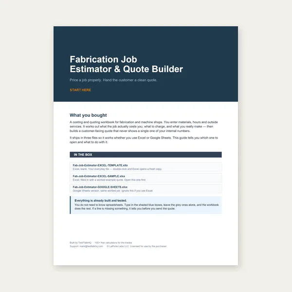
Price the job, then hand over a quote with no internal numbers.
Excel or Google Sheets. Best on a computer.
$29.00
Buy
Card, 19-page guide and the estimator workbook. All six files.
Excel or Google Sheets. Best on a computer.
$34.99
$45.98 if bought separately — save $10.99
BuyCheckout opens here — you stay on this page.