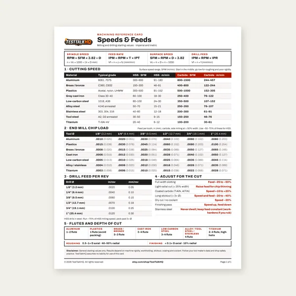
Machining Speeds & Feeds Card
One page. Speeds, chip load and drill feed, imperial and metric.
$3.99
BuyMinimum bend radius, springback, press brake setup, and K-factor explained
Getting a bend right the first time requires more than just setting an angle on the press brake. Material, thickness, radius, temper, grain direction, and springback all affect the outcome. This guide covers everything you need to know before you put metal in the brake — minimum bend radius by material, how to calculate and compensate for springback, air forming vs bottoming, and how press brake tooling selection affects your results.

Minimum bend radius is the tightest radius a material can handle without cracking on the outside of the bend. It's expressed as a multiple of material thickness. The table below covers the most common fab shop materials in soft, half hard, and full hard tempers.
| Material | Soft / Annealed | Half Hard | Full Hard |
|---|---|---|---|
| Mild Steel | 0.5× t | 1× t | 2× t |
| Stainless Steel | 1× t | 2× t | 3× t |
| Aluminum 5052 | 0.5× t | 1× t | 2× t |
| Aluminum 6061 | 1× t | 2× t | 4× t |
| Copper | 0.5× t | 1× t | 1.5× t |
| Brass | 0.5× t | 1× t | 2× t |
These are minimum values — always add a safety margin of at least 25% when possible. A 1×t minimum radius means if you're bending 0.060-inch steel, your inside radius should be no tighter than 0.060 inches. Going tighter risks cracking or fracturing the outer fiber of the material.
Grain direction matters more than most fabricators realize. Rolling direction creates a grain in the sheet. Bending perpendicular to the grain (across the rolling direction) can use a tighter radius. Bending parallel to the grain requires a larger radius — typically 50–100% larger than the cross-grain value. Mark your blanks for grain direction on critical parts. Use our Sheet Metal Bend Radius Calculator for exact minimum and recommended radii by thickness.
Springback is the elastic recovery that happens when the bending force is removed. Every metal has elastic memory — it wants to return to its original flat shape. The plastic deformation from bending is permanent, but the elastic portion springs back. The result is that your part opens up slightly after the punch retracts.
Springback varies by material strength and bend radius. High-strength materials spring back more. Tighter radii produce less springback because more of the deformation is plastic. The table below gives typical springback values per 90° of bend angle — scale linearly for other angles.
| Material | Springback per 90° Bend | Overbend To |
|---|---|---|
| Mild Steel | 2–5° | 85–88° |
| Stainless Steel | 5–10° | 80–85° |
| Aluminum 5052 | 3–6° | 84–87° |
| Aluminum 6061 | 8–15° | 75–82° |
| Copper | 1–3° | 87–89° |
| Brass | 2–4° | 86–88° |
Always run a test bend on scrap before production. Measure the actual springback, then dial in your overbend. Do not rely on published values alone — springback varies with tooling, material lot, and machine condition. The Sheet Metal Bend Radius Calculator estimates springback and overbend angles for your material and bend angle.
Air forming is the most common press brake method. The punch pushes the metal into the die but does not contact the bottom of the die — the metal bridges across the die opening. The bend radius achieved is approximately 16% of the die opening width, regardless of the punch nose radius. Air forming requires the least tonnage and is the most flexible method — one set of tooling can produce multiple radii by changing the die opening.
Bottoming (also called bottom bending) drives the punch until the metal contacts the bottom of the die, but does not fully squeeze the material. It produces a more consistent angle than air forming and reduces springback significantly because the material is more fully plastically deformed. Bottoming requires more tonnage than air forming — typically 3–5× more — and the punch nose radius must match the desired inside radius.
Coining fully plastically deforms the material between punch and die, essentially cold-working the metal into the tool shape. It produces the most accurate and consistent angles with the least springback, but requires 5–10× the tonnage of air forming and accelerates tooling wear. Coining is used in precision aerospace and electronics work where angle tolerance is critical.
One page. Speeds, chip load and drill feed, imperial and metric.
$3.99
Buy
27 pages. Milling, drilling, tapping, turning and CNC routing.
$12.99
Buy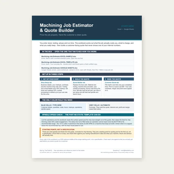
Quote shop work and check operations against your spindle's top speed.
Excel or Google Sheets. Best on a computer.
$29.00
Buy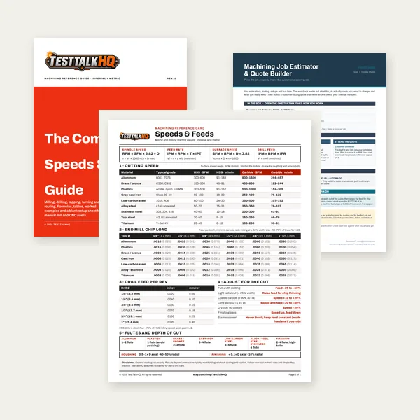
Card, 27-page guide and the estimator workbook. All six files.
Excel or Google Sheets. Best on a computer.
$34.99
$45.98 if bought separately — save $10.99
BuyCheckout opens in a new tab.
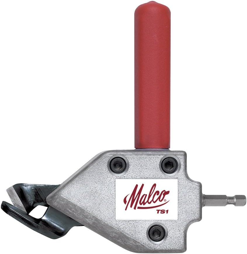
Radius gauges, cutting attachments, and cutting fluid for layout and press brake work


As an Amazon Associate, TestTalkHQ earns from qualifying purchases.
Tonnage required for air forming is calculated as: T = (575 × t² × L) / V where T is tons, t is material thickness in inches, L is bend length in inches, and V is the die opening in inches. This formula applies to mild steel — multiply by 1.4 for stainless, 0.5 for aluminum, and 0.5 for brass and copper. Use the Press Brake Tonnage Calculator for instant estimates and the Press Brake Tonnage Guide for air vs bottom bending.
Always stay within 80% of your press brake's rated tonnage. Exceeding rated tonnage damages the ram, bed, and tooling. For long bends on thick material, break the bend into multiple shorter strokes if your machine is undersized. Never place a short bend at the center of a long ram — the unsupported span creates a deflection bow that kills angle consistency.
The K-factor defines where the neutral axis sits within the material thickness during bending. It's a ratio between 0 and 0.5 — a K-factor of 0.5 means the neutral axis is at the center of the material. The neutral axis is the layer that neither stretches nor compresses during bending. Material on the outside of the bend stretches; material on the inside compresses; the neutral axis is where these cancel.
Bend allowance — the amount of flat material consumed in the bend zone — is calculated using the K-factor: BA = (π/180) × bend angle × (inside radius + K × thickness). Default K-factors: mild steel 0.44, stainless 0.44, aluminum 0.41, copper 0.43, brass 0.43. Use the Sheet Metal Bend Deduction Calculator for BD/K-factor flat patterns and the Sheet Metal Bend Allowance Calculator to compute flat pattern lengths once you have your radius and K-factor dialed in. Also see the Sheet Metal Bend Radius Calculator, Sheet Metal Gauge Chart, and Metal Gauge to Thickness Converter. Also see Tube Bending Calculator — CLR, Arc Length & Bend Deduction and Tube Bending Guide — CLR, Wall Thickness & Springback.
In air forming, the inside bend radius is determined by the die opening, not the punch nose radius. The rule of thumb is that the achieved inside radius equals approximately 16% of the die opening. A 2-inch die opening produces roughly a 0.32-inch inside radius.
This means you can change your bend radius without changing tooling — just change the die. Understanding this relationship is the key to flexible press brake setup.
6061-T6 is the standard structural aluminum but it's notoriously difficult to bend without cracking. Its low elongation (8–10%) means it can't handle tight radii. For any part that requires forming, 5052-H32 is the correct choice — it has 12–15% elongation and handles radii as tight as 0.5×t in the soft condition.
If 6061 must be bent, use the annealed (T0) condition and anneal the bend zone with a torch before forming.
Laser-cut and plasma-cut edges have a heat-affected zone and often a hardened edge that cracks more easily than the parent material. Always deburr and break the edge before bending — a sharp edge concentrates stress at the bend tangent line and initiates cracks even when the bend radius is within spec.
A quick pass with a file or deburring tool takes 30 seconds and prevents scrap parts.
Accurate bend line layout is essential for multi-bend parts. Mark bend lines with a scribe or fine marker — not a punch, which creates a stress concentration. On critical parts, use a digital angle gauge to verify each bend before moving to the next.
For production work, build a simple bend gauge or stop block to ensure repeatability. Never rely on the press brake's back gauge alone for the first article — always verify with a physical measurement.
When formulas look right but parts still fail, use Sheet Metal Bending Troubleshooting. When you need the BA vs BD workflow fork (not just the BA formula), use Bend Allowance vs Bend Deduction — Which to Use.
For developed cone, frustum, and lobster-back templates (printable PDF), use the Cone / Transition Flat-Pattern Generator, the usage guide, troubleshooting, and seam allowance by joining method.