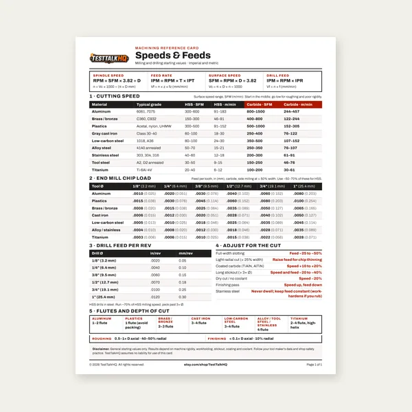
Machining Speeds & Feeds Card
One page. Speeds, chip load and drill feed, imperial and metric.
$3.99
BuyCLR, Bend Deduction, Wall Thickness & Settings for Round Tube & Pipe
Everything fabricators need to calculate centerline radius, bend allowance, minimum bend radius, and springback compensation for steel, aluminum, stainless, and chromoly tube.

Centerline radius (CLR) is the radius measured from the center of the bend arc to the centerline of the tube or pipe. It is the foundational dimension in all tube bending math — every other calculation, from bend allowance to die selection, starts here. CLR is not the inside radius and it is not the outside radius. It sits exactly in the middle of the tube wall, and that distinction matters when you're working to a print or fabricating a part that needs to match a pre-existing geometry.
To calculate CLR from a known inside radius: CLR = Inside Radius + (Tube OD ÷ 2). To work from the outside radius: CLR = Outside Radius − (Tube OD ÷ 2). In rotary draw bending, the CLR is set by the bend die you're using. A 2-inch CLR die on 1-inch OD tube produces a 2-inch centerline radius bend, a 2-to-1 D/t ratio (discussed below), and a specific arc length for any given angle.
When a fabrication drawing calls out a bend radius without specifying inside, outside, or centerline, clarify before cutting. In structural and mechanical drawings, most dimensions are given to the inside of the bend. In tube fabrication and roll cage work, CLR is the standard reference because it's the only radius that doesn't shift when you change wall thickness. A 2-inch CLR bend is a 2-inch CLR bend regardless of whether you're running 0.083-wall or 0.120-wall — the inside and outside radii both change, but the CLR doesn't.
Arc length — the actual length of tube consumed by the bend — is calculated as: Arc Length = (CLR × Bend Angle in Degrees × π) ÷ 180. For a 90° bend with a 3-inch CLR: (3 × 90 × 3.14159) ÷ 180 = 4.712 inches of tube consumed. This is critical for layout: if you don't account for arc length, your straight tangent lengths will come out short.
Bend allowance and bend deduction are the two methods fabricators use to reconcile the flat-layout length of a piece with its bent final shape. They measure the same reality from opposite directions, and confusing them is one of the most reliable ways to produce a part that's wrong in a way that's hard to diagnose.
Bend allowance is the length of material along the neutral axis that is consumed by the bend. The neutral axis is a theoretical line inside the tube where material is neither in tension (outer wall) nor compression (inner wall). For tube and pipe, the neutral axis sits at roughly 40–45% of the wall thickness from the inside of the bend, rather than exactly at the centerline. At tight bend ratios where the outer wall stretches and inner wall buckles significantly, the neutral axis shifts further inward.
For practical shop purposes, bend allowance is calculated as: BA = (π ÷ 180) × Bend Angle × CLR. This gives you the arc length at the centerline — a close enough approximation for most fabrication work. For tight-radius or precision aerospace work, you'd incorporate a K-factor to account for the neutral axis offset, but for structural tube bending, CLR-based arc length is the standard approach.
Bend deduction tells you how much shorter the total straight-line distance of the legs becomes once you add the bend. If you have a part with two straight legs and a 90° bend in the middle, the overall straight-line length of both legs does not add up to the total tube length required — the material consumed in the arc has to come from somewhere. Bend deduction = (2 × Tangent Length of Bend) − Bend Allowance. Tangent length for a 90° bend = CLR × tan(45°) = CLR × 1.0.
In practice, most tube benders work from bend allowance and mark tube layout directly: measure from the end of the tube to where the bend begins (the tangent point), make a reference mark, and load accordingly. Bend deduction becomes more important in sheet metal work where you're calculating blank lengths from finished dimensions, but it applies equally when you're figuring total tube length for a compound-bend assembly. Both values are accessible through a tube bending calculator when you input diameter, wall, CLR, and bend angle.
The D/t ratio — outside diameter divided by wall thickness — is the single most important number for predicting whether a bend will succeed or fail. A high D/t ratio means a thin-walled tube relative to its diameter. Thin-walled tubes are harder to bend cleanly because there's less material on the inner wall to resist compressive buckling, and the outer wall has less thickness to carry the tensile stress without thinning to failure.
A 1-inch OD tube with 0.065-inch wall has a D/t of 15.4 — a relatively thin wall. The same 1-inch tube in 0.120-inch wall has a D/t of 8.3. The thick-wall tube can be bent to a much tighter CLR without wrinkling or collapsing. General guidelines for minimum CLR as a multiple of OD:
For D/t ratios under 10 (heavy wall): minimum CLR is typically 1.5× to 2× OD. For D/t ratios 10–15 (medium wall): 2× to 3× OD minimum. For D/t above 15 (thin wall): 3× OD and above, often requiring a mandrel. These are starting points — material hardness, bend angle, and lubrication all shift the actual limit in practice.
Wall thinning on the outside of the bend is unavoidable. At the neutral axis the wall is undisturbed; outside of it, material stretches and the wall gets thinner. A general estimate for outer wall thinning: Thinning % ≈ (OD ÷ (2 × CLR)) × 100. For a 2-inch OD tube bent on a 3-inch CLR: (2 ÷ 6) × 100 = 33% wall thinning on the outside. That's extreme and would typically require a mandrel, heavy-wall tube, or a larger CLR die. For structural applications, keeping outer wall thinning under 20% is a reasonable guideline; pressure-carrying pipe is more restrictive.
The relationship between bend radius and cross-section deformation (ovality) follows a similar curve. Tighter CLR = more ovality. A tube that starts perfectly round will flatten into an ellipse during bending, especially without a mandrel to support the bore. Acceptable ovality limits vary by application: 5% for pressure applications, 8–10% for structural, higher for purely aesthetic bends.
The bending process determines what level of quality and precision is achievable. Each method has a domain where it performs best and a set of conditions where it fails. Using the wrong process for your tube and CLR combination is the most common root cause of bent-tube quality problems.
Rotary draw bending uses a fixed bend die matched to the CLR and OD of the tube, a clamp die that holds the tube against the bend die, and a pressure die that follows the tube and controls the feed side. A mandrel — a precision-ground steel plug or ball-and-shank assembly — inserts into the bore of the tube at the bend point and supports the inner wall from collapsing. A wiper die may be added at the tangent point to prevent wrinkling on the intrados.
Mandrel bending is the correct process for thin-wall tube, tight CLR bends (under 3× OD), and any application requiring consistent cross-section and surface finish across production quantities. It's the standard for automotive exhaust, roll cages, chassis tubing, aerospace ducting, and hydraulic line fabrication. The tradeoff is tooling cost: you need a matched die set for each OD/CLR combination, and mandrel positioning and lubrication are setup variables that require tuning per material and wall thickness.
On heavier-wall tube with generous CLR, mandrel-less rotary draw bending produces good results. The tube's own wall stiffness resists collapse, and the pressure die controls the feed without needing internal support. This is common for structural steel tube and pipe where the D/t is low (wall is heavy), and for mild steel DOM where some ovality is acceptable. It's faster setup than mandrel bending and eliminates the need for internal lubricant.
Compression bending holds one end of the tube fixed and pushes the other end around a stationary form die. The tube is wrapped around the outside of the die by a moving wiper or follower. It's the simplest and cheapest bending process — cheap tooling, no clamp die, no mandrel — but it produces the most distortion. The inner wall buckles and wrinkles under compression because nothing is restraining it. Compression bending is acceptable for thin-gauge conduit, decorative tube, and low-pressure fluid lines where ovality and inner-wall roughness don't matter. It's not suitable for structural chromoly, thin stainless, or any tube requiring clean bore geometry.
Three-roll bending uses a pyramid or variable-geometry arrangement of three rollers to progressively work the tube into a curved arc. It's the method for large-radius bends — sweeping curves on handrail, architectural tube, roll bar hoops with very large CLR, and pipe coils. It cannot achieve the tight radii that rotary draw bending can, and it produces more ovality per bend than mandrel draw bending. However, it has no practical upper limit on bend angle (you can make a full circle) and can handle very large diameter material that no draw bender can accommodate. For typical structural fabrication, roll bending is used when CLR exceeds about 8× OD.
Push bending adds a compressive axial force to the tube during bending — essentially pushing material into the bend zone from the trailing end to compensate for wall thinning on the outside. It's a more sophisticated variant used in CNC bending of thin-wall tube for exhaust and aerospace applications. The boost force keeps the outer wall from thinning as severely and reduces mandrel wear. It requires a machine capable of coordinating rotation and axial push simultaneously, which is not available on most manual or basic CNC benders.
Every material bends differently. The same CLR and wall thickness that produces a clean bend in mild steel will wrinkle in stainless, crack in hard aluminum, and springback excessively in chromoly. Knowing the behavior of your material before you set up the machine saves tooling, time, and tube.
Mild steel is the easiest material to bend. It's ductile, forgiving of moderate variations in speed and lubrication, and has relatively low springback at standard CLR ratios. ERW (electric resistance welded) mild steel tube is widely available and cheap, but the weld seam can be a point of weakness on the intrados. Position the weld seam at 90° to the plane of the bend — at the neutral axis — to avoid putting the seam into compression or tension. DOM (drawn over mandrel) mild steel is seamless or has a welded seam that's been cold-worked until the seam is indistinguishable from the parent material; it bends more uniformly than ERW and is preferred for structural applications. Minimum CLR for mild steel is typically 1.5× OD for heavy wall with mandrel support, 2× OD for standard wall in production bending.
DOM is a specific manufacturing process rather than a material grade — it's typically 1020 or 1026 steel. The drawing process cold-works the material, improving its mechanical properties above base ERW. DOM has better surface finish inside and out, tighter dimensional tolerances on OD and wall thickness, and more consistent ductility than standard ERW. For roll cage work, chassis fabrication, and any high-cycle or high-load application, DOM is the correct choice over standard ERW. It bends similarly to mild steel but with more consistent results part to part due to tighter material tolerances.
Aluminum is more difficult to bend than mild steel for several reasons. First, it has a lower elongation at fracture than mild steel — it cracks before it deforms as much as steel. Second, age-hardened alloys like 6061-T6 have a relatively narrow range between yield and ultimate tensile strength, meaning the material goes from elastic to fracture with less plastic deformation in between. Third, the oxide layer on aluminum has different friction characteristics than steel, and lubrication choice matters more.
For 6061-T6, minimum CLR is typically 3× OD with a mandrel; tighter bends are possible but risk cracking on the outer wall. 3003 and 6063 alloys are much more ductile and can be bent to 1.5× OD or tighter with proper support. If your application allows it, bending 6061 in the annealed (T0) condition and then age-hardening afterward produces much cleaner bends, though this requires access to a heat treatment process and careful temperature control. Springback in aluminum is significant — 5° to 15° or more depending on alloy and temper — and must be dialed in empirically for each setup.
Stainless is harder to bend than mild steel in every way: it's stronger, it work-hardens rapidly as it deforms, it galls against tooling without proper lubrication, and it springbacks more. The work-hardening characteristic of austenitic stainless (304, 316) means the material gets harder as you bend it, which progressively increases springback mid-bend on a slow or stalled bender. Bending stainless requires sharp, well-fitted tooling with minimal clearance, aggressive lubrication (chlorine-free for 316 to avoid pitting), and enough machine power to maintain consistent speed through the full bend angle without hesitation. Die clearances that work fine for mild steel will allow stainless to slip and wrinkle. Springback for 304 stainless is typically 5° to 12° at standard CLR ratios and must be characterized per setup.
4130 chromoly in the normalized condition is more ductile than its reputation suggests. It bends cleanly with proper support and lubrication and is commonly used in aircraft fuselage tube, race car roll cages, and high-strength chassis components. The key is wall thickness: chromoly is used in thinner walls than mild steel for equivalent strength, which means higher D/t ratios and more tendency to collapse without mandrel support. Minimum CLR for chromoly is typically 2× OD with mandrel; the SFI and FIA cage specifications for motorsport specify minimum bend radii for this reason. Post-bend normalizing is sometimes specified for 4130 to relieve residual stresses, particularly on tight-radius bends in critical structural applications, but in most fabrication shops this is skipped for tack-welded assemblies where the weld heat partially stress-relieves the adjacent material anyway.
A rotary draw bender has five tooling components: the bend die, the clamp die, the pressure die, the mandrel, and the wiper die. Getting the machine dialed in for a new tube and CLR combination requires setting all five correctly. A mistake in any one of them produces a defect that's often blamed on the wrong component.
The bend die sets the CLR and must match the OD of your tube. The groove radius in the die equals the tube OD divided by 2. The die should cradle the tube with the groove tangent to the tube surface — not a tight squeeze (which deforms the tube against the die) and not loose (which lets the tube shift and wrinkle). Die material matters: for mild steel tube, cast iron or steel dies are standard; for stainless and aluminum, consider chrome-plated or aluminum bronze dies to reduce galling.
The clamp die holds the straight section of tube against the bend die immediately behind the start of the bend. Clamp pressure must be sufficient to prevent the tube from slipping during the bend without crushing the tube OD. Too little clamp pressure and the tube walks forward during the bend, destroying the tangent-point reference and producing a longer, sloppier arc. Too much pressure and you crush the OD. Set clamping pressure to the minimum that prevents slippage — start conservatively and increase in small increments if slipping occurs.
The pressure die rides against the outside of the straight feed section and controls the tube as it feeds into the bend. Its job is to prevent the tube from lifting away from the bend die and to control the column load on the trailing end. Pressure die clearance (the gap between the die groove and the tube OD) should be approximately 5–10% of wall thickness — just enough to move freely without grabbing. Pressure die force should be set to hold the tube firmly but not so high that the die drags and causes the tube to stretch rather than bend.
The mandrel tip should be positioned at or just slightly ahead of the tangent line — the exact point where the straight section of tube begins to curve. If the mandrel is too far back (inside the straight section), the tube can wrinkle just past the tangent point where the mandrel provides no support. If the mandrel is too far forward (into the bend itself), it will kink the tube and potentially damage the mandrel or machine.
Mandrel type depends on D/t ratio and CLR. A plug mandrel (solid ball or cone) works for moderate wall thickness and generous CLR. A single-ball mandrel (a hinged ball on a shank) works for thinner wall and tighter CLR by providing support further into the bend radius. Multi-ball mandrels (two or more linked balls) are used for very thin wall or very tight CLR bends where support is needed well into the arc. Ball count: one ball for CLR ÷ OD ratios down to about 1.5; two balls for ratios approaching 1.0; three or more for extreme thin-wall aerospace tube.
The wiper die sits just upstream of the tangent point on the intrados side and prevents wrinkling by supporting the inner wall as it is put into compression. The wiper die tip should be positioned as close to the tangent line as possible without extending into the bend — the tip must be sharp (not radius-broken) and polished. A wiper die with a rounded tip or set back from the tangent will fail to catch wrinkles at the point where they start. Wiper dies require aggressive lubrication — this is where galling occurs most often in stainless and aluminum bending.
Mandrel and wiper die lubrication is critical. The mandrel moves through the tube as the bend is pulled, generating friction against the inner bore. Without lubrication, the mandrel drags, the outer wall thins unevenly, and the surface finish inside the tube is destroyed. Use a water-soluble mandrel lubricant applied to the mandrel shank and balls before each bend. For stainless, use a chlorine-free lubricant. For aluminum, a dedicated aluminum bending lubricant or clean petroleum-based oil prevents the galling that causes surface tearing. Wipe down the bend die groove and clamp die groove as well — contamination in the groove marks the tube OD.
Every metal has an elastic range — a zone of deformation that is recoverable. When you bend a tube to 90° and release it, the elastic portion of the deformation springs back and the finished angle is less than 90°. This is springback, and it's present in every bend in every material. The only question is how much.
Springback is driven by the ratio of the material's yield strength to its elastic modulus (Young's modulus). Higher yield strength relative to elastic modulus = more springback. This is why high-strength alloys like 4130 chromoly and 304 stainless springback more than mild steel: their yield strength is much higher, but their elastic modulus (approximately 29–30 million psi for all ferrous materials, 10 million psi for aluminum) is essentially the same. Harder temper aluminum alloys springback more than annealed or softer temper alloys for the same reason.
Springback also increases as CLR increases relative to tube diameter. Tighter bends — lower CLR/OD ratios — produce more plastic deformation relative to elastic deformation, so springback as a percentage of the total bend angle is smaller. At very tight radii (CLR = 1× OD), springback is minimal because the material has been plastically deformed so severely that little elastic recovery is possible. At large CLR/OD ratios (CLR = 5× OD and above), springback can be 10–15° or more and becomes the dominant challenge.
The standard approach is overbend: set the machine to bend past the target angle by the amount the material springs back, so the final rested angle hits the target. For a 90° bend in DOM mild steel at 2× CLR, springback might be 3–5°, so you set the stop at 93–95°. This springback value must be characterized empirically for each material-CLR-wall combination — reference charts give a starting point, but the actual value depends on specific material temper, wall thickness consistency, lubrication, and machine characteristics.
A calibration bend procedure: bend a test piece to 90°, release, measure the actual angle, and calculate the springback. Input that value as your overbend angle and run another test. Iterate until you're within ±0.5° of target. Document the springback for that setup so you don't have to re-characterize on future runs with the same tube and die combination.
Some CNC benders have springback correction built into their control software, which can store and apply per-material correction factors automatically. Even so, the machine's stored springback value requires periodic verification — material lots vary, worn tooling changes the bend characteristics, and lubrication condition shifts the results.
Most tube bending defects trace back to a small set of root causes. Understanding which defect maps to which cause gets you to the fix without wasting tube on speculative adjustments.
Wrinkles are caused by the inner wall buckling under compression. This is a tooling geometry or setup problem, not a material problem. The most common causes: wiper die tip set too far back from the tangent line, wiper die tip worn or radius-broken, insufficient wiper die pressure, or mandrel positioned too far back. Check the wiper die tip position first — it should be within 0.005–0.010 inches of the tangent line. If the tip is correctly positioned and wrinkles persist, check mandrel ball position and ensure the ball extends to the tangent point. Wrinkling in the middle of the arc (not just at the start) typically indicates insufficient mandrel length or missing additional balls.
Some ovality is unavoidable without a mandrel. Excessive ovality with a mandrel installed indicates the mandrel is undersized for the tube bore (worn balls or wrong mandrel), or the mandrel is positioned too far back. Measure mandrel ball diameter and compare to minimum bore specification — mandrel ball diameter should be within 0.005–0.010 inches of the tube ID. Ovality that worsens at the end of the bend often indicates mandrel balls that are too far forward or the wrong ball count for the CLR being run.
Excessive wall thinning on the extrados (outside of bend) is a material and CLR problem. The bend radius is too tight for the wall thickness and material elongation. Solutions in order of preference: increase CLR (use a larger bend die), increase wall thickness (use heavier-wall tube), or switch to a more ductile material. If you're already at the minimum acceptable CLR and can't change the material, add boost pressure if your machine supports it — compressive axial force reduces outer wall thinning. Cracking is the terminal result of excessive thinning — if cracks appear, the CLR is too tight for the material and no amount of mandrel adjustment will fix it.
Tube slippage shows up as a longer-than-specified arc at a given angle, a loss of tangent-point reference, and often marks or crushing on the tube OD where the clamp over-gripped in compensation. Increase clamp die pressure incrementally. If slippage persists at high clamp pressure, check the clamp die groove for contamination or wear. For stainless and aluminum, clamp die galling is common — a thin layer of tube material transfers to the die groove and reduces grip. Clean the die groove and apply a thin film of anti-seize to the die (not the tube surface) to prevent transfer.
If repeated bends on the same setup produce varying angles, the causes are: inconsistent material (lot-to-lot yield strength variation), inconsistent lubrication, or temperature variation in the machine (most relevant on production runs where the machine warms up and tool dimensions shift slightly). For production work, run a warm-up bend before the first production piece and re-verify the springback after every 20–30 bends or any machine stop of more than 15 minutes.
This section provides a condensed diagnostic framework for the three most common tube bending failures.
Symptom: Corrugated ridges on the inner wall of the bend.
Primary cause: Inner wall buckling under compressive load without adequate lateral support.
Check in order: (1) Wiper die tip position — advance toward tangent line. (2) Wiper die tip condition — sharpen or replace if worn. (3) Mandrel position — advance toward tangent. (4) Mandrel ball count — add a ball if wrinkles appear mid-arc. (5) Die fit — verify groove radius matches tube OD within tolerance. (6) If all tooling is correct and wrinkles persist, the CLR is too tight for the material and wall thickness.
Symptom: Cross-section deforms from round to elliptical through the bend.
Primary cause: Insufficient internal support.
Check in order: (1) Is a mandrel installed? For D/t above 12 and CLR below 3× OD, a mandrel is required. (2) Mandrel ball diameter — balls must fit the bore within 0.010 inches. (3) Mandrel position — too far back leaves the bend unsupported at start. (4) Number of mandrel balls — tight CLR requires multiple balls to support further into the arc. (5) If mandrel tooling is correct and ovality exceeds tolerance, increase CLR or wall thickness.
Symptom: The tube wall caves inward on the intrados at the bend, producing a severe, non-recoverable deformation.
Primary cause: Complete failure of the inner wall under compression — an advanced case of what wrinkles precede.
Check in order: (1) D/t ratio — if OD divided by wall thickness exceeds 20–25, the tube is highly collapse-prone and requires a mandrel with multiple balls and an aggressive wiper die. (2) Mandrel presence and condition — collapse without a mandrel on thin-wall tube is expected, not a defect. (3) Bend speed — too slow gives material time to buckle progressively; maintain consistent bend speed. (4) Lubrication — high friction on the inner bore creates resistance that can deflect the tube away from the bend die and into collapse. If the tube collapses with correct tooling, the CLR is below the material's minimum for that wall.
One page. Speeds, chip load and drill feed, imperial and metric.
$3.99
Buy
27 pages. Milling, drilling, tapping, turning and CNC routing.
$12.99
Buy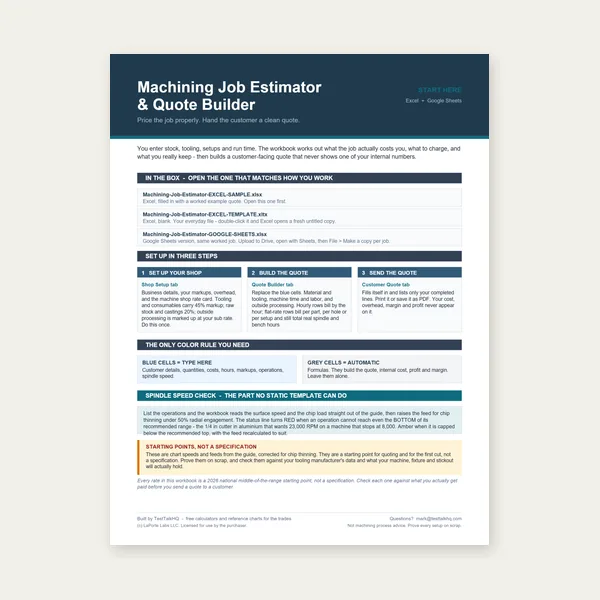
Quote shop work and check operations against your spindle's top speed.
Excel or Google Sheets. Best on a computer.
$29.00
Buy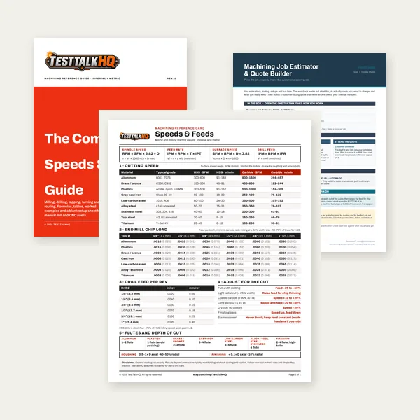
Card, 27-page guide and the estimator workbook. All six files.
Excel or Google Sheets. Best on a computer.
$34.99
$45.98 if bought separately — save $10.99
BuyCheckout opens in a new tab.
Deburring, measurement, lubrication, and PPE for tube and pipe fabrication


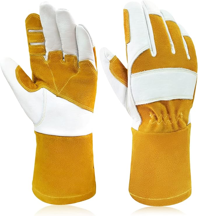
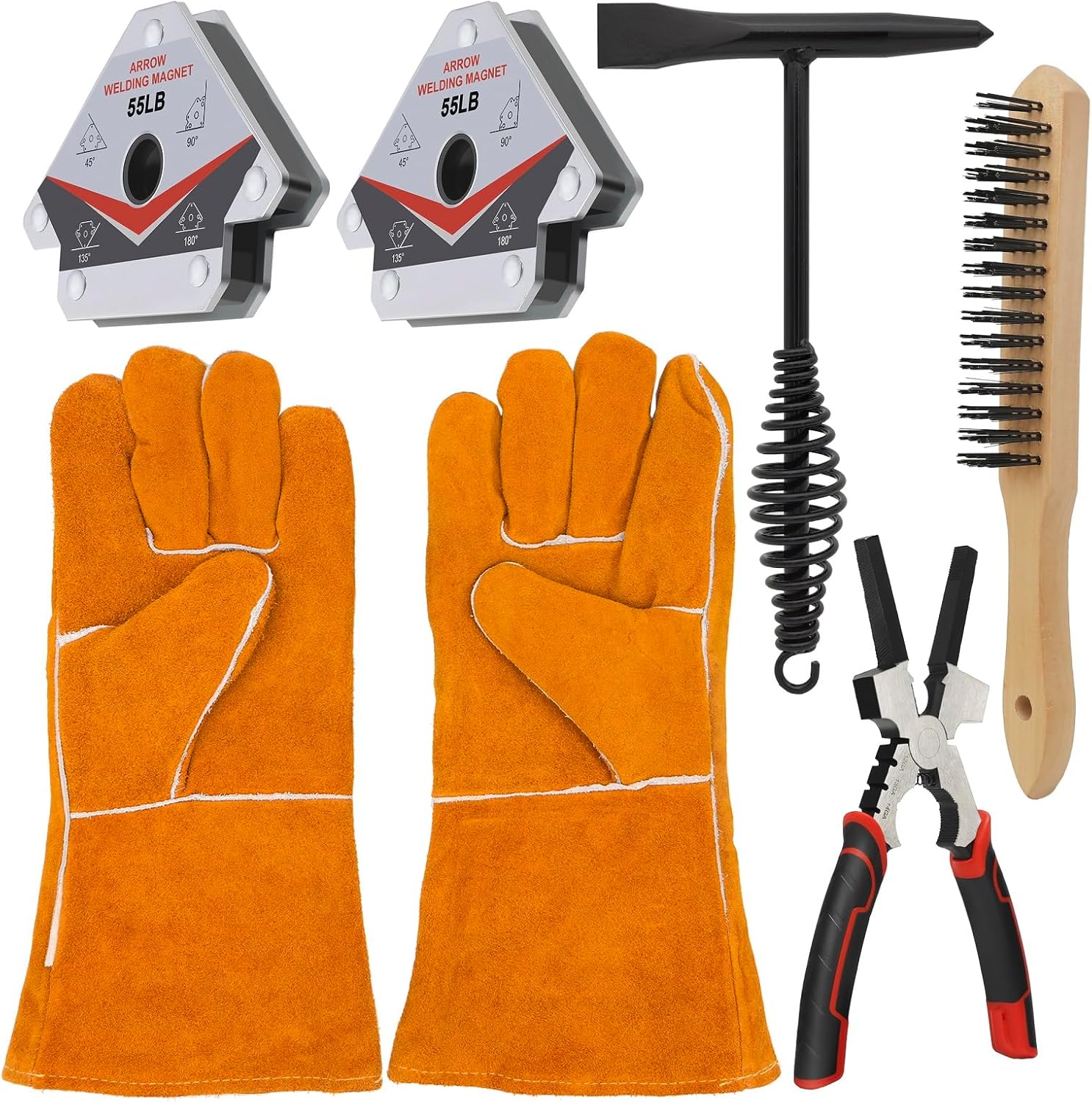
As an Amazon Associate, TestTalkHQ earns from qualifying purchases.
Centerline radius (CLR) is the starting point for every tube bending calculation. It sets the arc length your tube will consume, which directly determines how long your straight tangent sections need to be. Bend allowance — the length of material used in the arc — is calculated from CLR, not inside or outside radius. If you're working from a print that specifies inside radius, add half the tube OD to get CLR. Miss this step and every measurement downstream is wrong. Use a tube bending calculator to get accurate arc lengths and total blank lengths before you cut anything.
The bending process you choose determines what wall thickness, CLR, and material combinations are achievable. Rotary draw bending with a mandrel handles the widest range: thin wall, tight CLR, demanding materials like stainless and chromoly. Compression bending is cheaper to set up but produces more distortion — acceptable for conduit and decorative work, wrong for structural tube. Roll bending is the method for large-radius sweeps where draw bending tooling would be impractically large. Matching process to application is not a preference; it's the difference between parts that meet spec and parts that don't.
Every material bends differently, and springback is the most visible difference. Mild steel is forgiving; 304 stainless work-hardens as it bends and springs back 5–12°; 6061-T6 aluminum has a narrow plastic range and cracks before it wrinkles. Chromoly bends cleanly in normalized condition but needs more support than mild steel at the same wall thickness. Before you run production bends in any material, run a calibration piece, measure actual springback, and set your overbend accordingly. A reference chart gives you a starting point — the actual number comes from your specific tube lot, tooling, and machine.
Wrinkles, ovality, and wall thinning all look different but trace back to the same root causes: the CLR is too tight for the wall thickness and material, the tooling is wrong or worn, or the setup is incorrect. Wrinkles mean the inner wall lacks support — check wiper die position and mandrel tip first. Ovality means the bore is unsupported — check mandrel ball size and position. Excessive wall thinning means the outer wall is being stretched beyond its limit — the CLR needs to increase or the wall needs to get heavier. Fix the root cause; adjusting clamp pressure or bend speed won't cure a tooling geometry problem.
Minimum bend radius is the tightest CLR at which a given tube can be bent without wrinkling, collapsing, or cracking the outer wall. It depends on tube OD, wall thickness (expressed as the D/t ratio), material ductility, and whether a mandrel is used. A general starting point: minimum CLR ≈ 1.5× to 2× OD for heavy-wall mild steel with a mandrel; 3× OD for thin-wall or aluminum. To calculate more precisely, use the D/t ratio and the material's elongation percentage — higher D/t and lower elongation both push the minimum CLR upward. The reliable approach is to run a calibration bend at your target CLR, inspect for defects, and adjust. No formula substitutes for a test bend in the actual material and wall you're running.
Bend a test piece to your target angle, release the clamp, and measure the actual final angle with a digital angle gauge or protractor. The difference between the target and the measured angle is your springback. Set your machine's degree stop to (target angle + springback) and run another test piece. Repeat until the rested angle is within ±0.5° of target. Document this value for the specific tube OD, wall, material, and CLR combination — it will vary between setups. Springback is not a fixed material property; it shifts with lubrication condition, bending speed, tooling wear, and lot-to-lot variation in material yield strength, so verify periodically on long production runs.
Wrinkles form when the inner wall of the tube buckles under the compressive load of bending without adequate lateral support. The primary tooling controls are the wiper die and the mandrel. The wiper die tip must be positioned as close to the tangent line as possible — even 1/16 inch too far back creates an unsupported zone where the compression begins. The mandrel must extend to the tangent line and have enough ball length to support the arc. If both are correctly positioned and wrinkles persist, the CLR is too tight for the wall thickness and material — the solution is a larger bend die, a heavier wall tube, or a more ductile material, not further wiper die adjustment.
A mandrel is needed when the D/t ratio (OD ÷ wall thickness) exceeds approximately 10–12, when the CLR is below 3× OD, or when the application requires minimal ovality and clean bore geometry. Below those thresholds in mild steel or DOM, heavy-wall tube can often be bent without a mandrel with acceptable results. For material type: plug mandrels (solid) suit moderate wall and generous CLR; single-ball mandrels are for thin wall and tighter radii; multi-ball mandrels are for thin-wall tube at tight CLR where support is needed well into the bend arc. Ball count is determined by the arc length being supported — one ball covers roughly 30–45° of arc; add balls as CLR gets tighter relative to OD, since the same arc degree covers a shorter physical distance and the unsupported zone grows.