
Where each baseline reading comes from, the one that is nearly always taken wrong, and five complete jobs with the arithmetic done out loud
The arithmetic takes thirty seconds. Getting four honest numbers to put into it takes an hour, and that hour decides whether the answer is engineering or decoration. Below is what each of the four readings actually is, the specific way each one gets taken wrong, and then five complete changes — two of them lifted straight from the manufacturers’ own engineering guides — worked all the way through so you can follow every step.
Four numbers, and nothing else
A fan law calculation needs exactly four readings from the fan as it runs today, plus one statement of what you want to change. That is the entire input list.
| Reading | What it actually is | How it is usually got wrong |
|---|---|---|
| Airflow, CFM | What the fan is moving through this duct, right now | Taken from a nameplate or a blower table instead of measured |
| Static pressure, in. w.c. | What this duct demands at that airflow | Read with the filter out, or only on one side of the air handler |
| Fan speed, RPM | The speed of the wheel, not the motor | Assumed from the motor nameplate on a belt drive, where they differ by the sheave ratio |
| Power | Shaft power into the wheel, or the electrical watts that produce it | Calculated as amps times volts, which on an induction motor is not watts |
Two of those four have whole guides of their own on this site, and there is no point repeating them here. Taking a total external static pressure properly — where the probes go, which side of what, and what to do when the two readings disagree — is covered in the external static pressure guide and its troubleshooting companion. Turning a velocity reading and a duct area into a CFM figure is in the duct CFM guide, and the choice of instrument is settled in anemometer vs flow hood. What follows assumes you can take those two and concentrates on the two that are specific to fan law work: the speed, and the power.
The power reading, and the error that costs a third
This is where fan law calculations go wrong most often, and the error always runs in the same direction.
On an induction motor, apparent power — amps multiplied by volts — is not real power. The two differ by the power factor, which on a lightly loaded single-phase motor can sit at 0.6 or below and which changes with load. Use volt-amps where watts belongs and your computed power is too high, which in turn makes the fan look less efficient than it is. Work backwards from that figure to size a motor and the error propagates with the cube.
There are three honest routes to the power number, in descending order of how much you should trust them:
- Brake horsepower from the manufacturer rating table, read at your measured airflow and static pressure. This is the number the fan laws were written around. Twin City prints BHP in the same table as the RPM, so you read both at once.
- Measured true watts at the motor, de-rated by motor and drive efficiency. Shaft power is input watts times efficiency, divided by 746 watts per horsepower. Small PSC motors are poor — commonly 50 to 70 percent — and larger three-phase motors near full load are good, commonly 85 to 92. A belt takes a few more percent.
- An assumed fan static efficiency, which is a guess with a number attached. It is better than nothing and it is worth being clear about what it is.
The useful thing is that the third route also gives you a check on the first two. Twin City defines static efficiency as:
SE = CFM × SP × 100 ÷ (6356 × BHP)
Put your four readings in. If the answer comes out above 100 percent, the fan is producing more air power than it consumes, which it is not — one of the four numbers is wrong, and it is usually the power. If it comes out in single figures on a commercial fan, same conclusion. Small residential direct-drive blowers genuinely do run at poor static efficiencies, so a low figure there may be real, but it is worth a second reading either way.
Example A — Twin City’s own: 33,120 to 41,500 CFM
This one is worked in the Twin City Fan & Blower Engineering Resource Guide, so the published answer is there to check against. A 490 BC single-width fan is running at 33,120 CFM at 2.5 in. SP, turning 620 RPM and absorbing 20.01 BHP, on a 25 HP motor. The plant manager wants 41,500 CFM.
| Step | Working | Result |
|---|---|---|
| 1. The speed ratio | 41,500 ÷ 33,120 | 1.25302 |
| 2. New fan speed | 620 × 1.25302 | 777 RPM (published: 777) |
| 3. New static pressure | 2.5 × 1.25302 | 3.93 in. w.c. (published: 3.93) |
| 4. New brake horsepower | 20.01 × 1.25303 | 39.37 BHP (published: 39.39) |
| 5. Motor check | 39.37 against a 25 HP nameplate | 14.37 BHP over |
Read step 5 next to step 1. A +25.3 percent airflow increase produced a +96.7 percent power increase, and the source spells out the consequence: “The new performance increases the fan’s horsepower requirement from 25 HP to 50 HP. If the fan is sped up to 777 RPM the motor must be resized.” A quarter more air doubled the motor.
And then the instruction that is easy to skim past: “IMPORTANT NOTE: The new RPM should be checked to make sure it does not exceed the maximum allowable RPM for the fan that is installed.” Nothing in the three equations knows about that limit. It has to be looked up and checked separately, every single time.
Example B — the belt-drive air handler that cannot have what it needs
A commercial belt-drive air handler measures 1,200 CFM at 0.50 in. w.c., the wheel turns 900 RPM, and a true-power clamp reads 560 W into a 1/2 HP motor with a 1.15 service factor. The coil needs 1,400 CFM. The motor sheave is 2.8 in pitch diameter and the cataloged maximum safe speed is 1,200 RPM.
| Step | Working | Result |
|---|---|---|
| 1. Shaft power now | 560 W × 0.70 ÷ 746 | 0.5255 BHP |
| 2. Sanity check | 1,200 × 0.50 × 100 ÷ (6356 × 0.5255) | 18.0 percent static efficiency — low, but normal for this class |
| 3. The speed ratio | 1,400 ÷ 1,200 | 1.16667 |
| 4. New fan speed | 900 × 1.1667 | 1,050 RPM — inside the 1,200 limit |
| 5. New static pressure | 0.50 × 1.16672 | 0.681 in. w.c. |
| 6. New shaft power | 0.5255 × 1.16673 | 0.8344 BHP |
| 7. What the motor allows | 0.50 HP × 1.15 | 0.5750 BHP |
| 8. Verdict | 0.8344 needed, 0.5750 available | 0.2594 BHP short |
| 9. Sheave, if it were viable | 2.8 in × 1.1667 | 3.27 in pitch diameter |
This is the shape of the job that goes wrong quietly. Everything looks modest: +16.7 percent more air, a sheave two sizes up, the speed comfortably under the wheel limit. But the power went up +58.8 percent, from 0.53 to 0.83 BHP, and a half-horse motor with a 1.15 service factor tops out at 0.575. At the wall that is 560 W going to 889 W.
Fit the sheave and the fan will turn. The motor will draw over nameplate, run hot, and fail somewhere between a season and a couple of years later, by which time nobody connects the failure to the sheave. The honest options are a bigger motor alongside the drive change, or opening the duct up so the same airflow needs less pressure — which is what the duct sizing calculator is for.
Any trade

Contractor Job Estimator
Price remodels and GC work, then send a quote with no internal numbers.
Excel or Google Sheets. Best on a computer.
$29.00
BuyCheckout opens in a new tab.
What the five examples needed
Four of the five worked examples below start from numbers somebody had to go and take. None of them needs anything exotic, and only one of them — the power — has a trap in it serious enough to change the answer by a third.

NEIKO 20713A Digital Laser Tachometer
- The wheel RPM every one of these examples scales from
- Non-contact off a strip of reflective tape on the hub
- Fan speed and motor speed are different on every belt drive
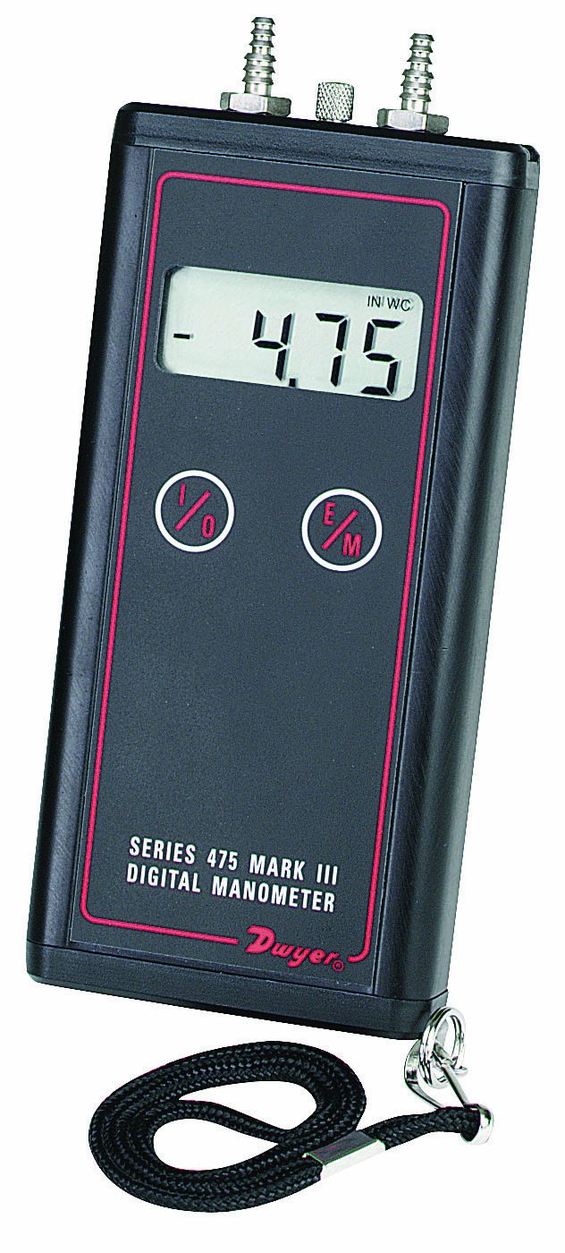
Dwyer Series 475 Mark III Digital Manometer
- The inches of water column the second fan law squares
- Supply and return added, with the filter in place
- Also the reading that says whether the duct is the real problem
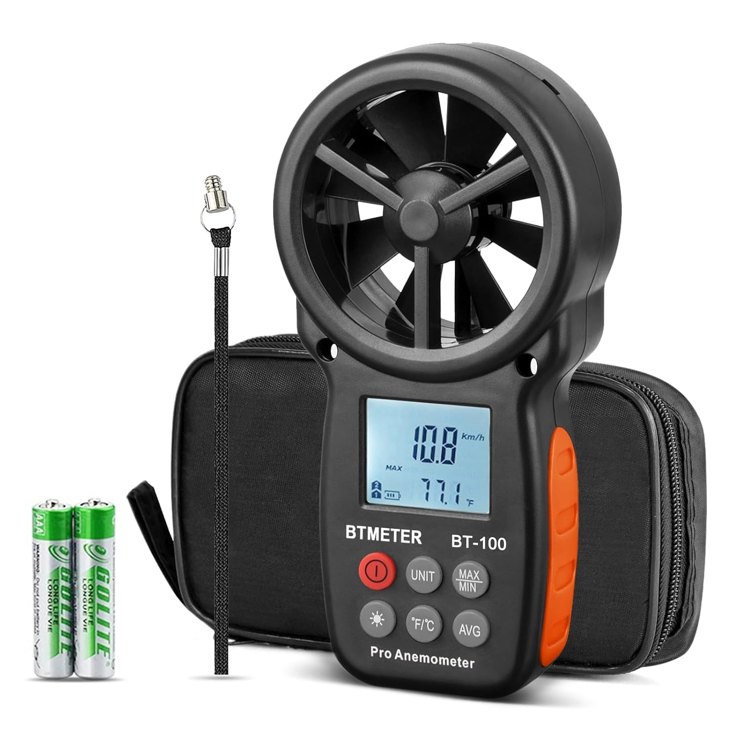
BTMETER BT‑100 Handheld Anemometer
- Face velocity at a grille, which becomes the CFM you scale
- A measured figure instead of a nameplate one
- And the way you confirm the new speed actually delivered
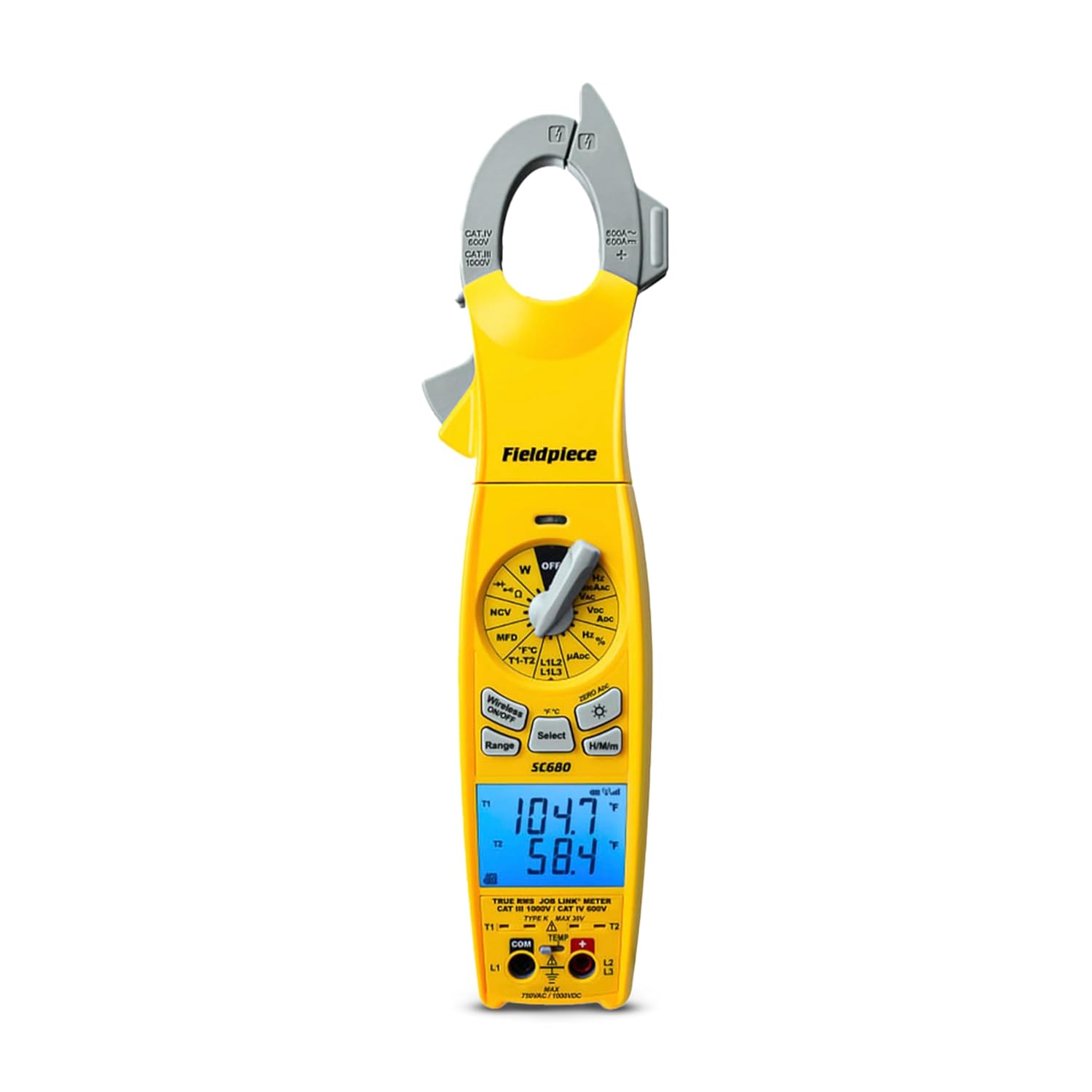
Fieldpiece SC680 Wireless Clamp Meter
- Running amps against nameplate is the motor headroom check
- Catches a motor already in its service factor before you start
- True RMS, so a drive output does not fool it
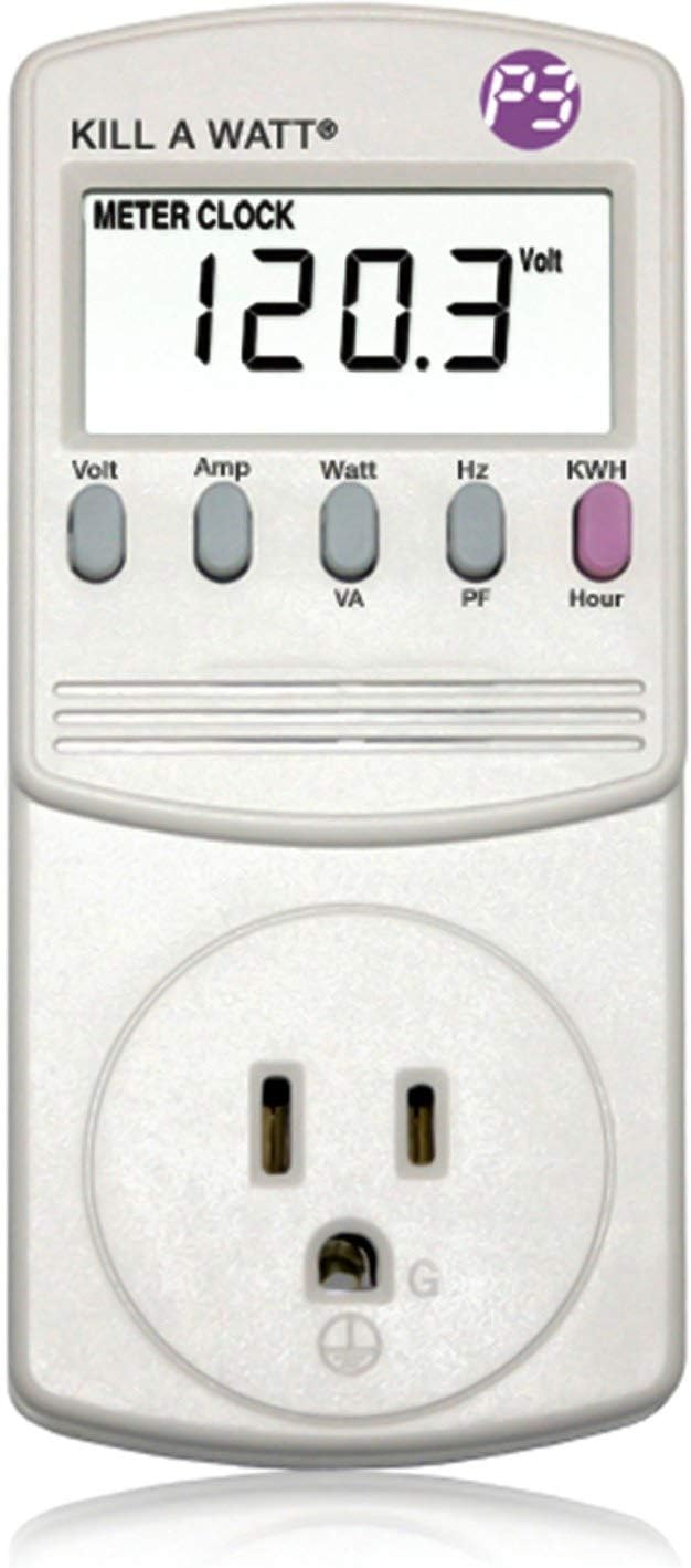
P3 P4400 Kill A Watt Energy Monitor
- True watts for a plug-in air handler, straight off the display
- Removes the volt-amps error that makes the power read high
- Cheap enough to leave in place across a before and after
As an Amazon Associate, TestTalkHQ earns from qualifying purchases. Prices and availability can change.
Example C — the same arithmetic, running the other way
A commercial fan moves 8,000 CFM at 1.5 in. w.c. at 1,150 RPM, absorbing 3.4 BHP on a 5 HP motor. The space is over-ventilated and the building wants it dialled back to 80 percent speed on the drive.
| Quantity | At 100 percent | At 80 percent | Change |
|---|---|---|---|
| Fan speed | 1,150 RPM | 920 RPM | -20.0 percent |
| Airflow | 8,000 CFM | 6,400 CFM | -20.0 percent |
| Static pressure | 1.500 in. | 0.960 in. | -36.0 percent |
| Brake horsepower | 3.400 | 1.741 | -48.8 percent |
| At the motor | 2,984 W | 1,528 W | 1,456 W saved |
A fifth off the airflow and almost half the power gone. The same exponent that makes speeding a fan up so expensive makes slowing one down so cheap, and this asymmetry is the whole argument for variable-speed control over the older habit of throttling a fan with a damper. A damper adds resistance and slides the operating point up a fan curve that is still being driven at full speed; reducing the speed moves the entire fan curve down, and the power follows the cube.
Example D — hot gas, and the start that burns the motor
Twin City works this one too, and it is the example that teaches the thing most people have never been told. A 365 BC fan has to handle 17,000 CFM at 2.5 in. SP, at 300°F and 3,000 ft. The rating table is printed for standard air at 70°F and sea level. What do you look up, and what motor do you buy?
| Step | Working | Result |
|---|---|---|
| 1. Correction factor | (530 ÷ 760) × (26.82 ÷ 29.92) | 0.6250 (chart: 0.624) |
| 2. Operating density | 0.075 × 0.6250 | 0.04688 lb/ft3 |
| 3. SP to look up | 2.5 ÷ 0.625 | 4.00 in. w.c. (published: 4″) |
| 4. Table gives, at 17,000 CFM and 4″ | interpolated in the source | 918 RPM and 14.34 BHP (published: 14.36) |
| 5. Power actually absorbed hot | 14.34 × 0.625 | 8.97 BHP (published: 8.96) |
| 6. Cold-start power | 14.34 × 0.896 (the factor at 3,000 ft and 70°F) | 12.86 BHP (published: 12.87) |
| 7. Size the motor on | the larger of 8.97 and 12.86 | 12.86 BHP |
Step 5 and step 6 are the whole lesson. Running hot, the fan absorbs 8.97 BHP. Starting cold, in dense air at the same altitude, it absorbs 12.86 — 43 percent more. A 10 HP motor is comfortable all day on the running figure and is nowhere near enough on the starting one.
Notice too that the airflow never changed. A fan is a constant-volume machine: it sweeps the same cubic feet per revolution whatever the air weighs. What changes with density is the pressure it develops and the power it absorbs, both in direct proportion. Thin air, same CFM, less pressure, less power — and less mass of air, which is what actually carries the heat.
Example E — a Denver rooftop and a sea-level catalog
Same physics, ordinary job. A rooftop unit at 5,280 ft handles 95°F return air. It is measured at 6,000 CFM at 1.10 in. w.c., turning 1,050 RPM and absorbing 2.2 BHP on a 3 HP motor with a 4.0 in motor sheave. It needs 6,600 CFM.
| Step | Working | Result |
|---|---|---|
| 1. Speed ratio | 6,600 ÷ 6,000 | 1.1000 |
| 2. New fan speed | 1,050 × 1.10 | 1,155 RPM |
| 3. New motor sheave | 4.0 in × 1.10 | 4.40 in pitch diameter |
| 4. New static pressure, in this air | 1.10 × 1.102 | 1.331 in. w.c. |
| 5. Correction factor | (530 ÷ 555) × (24.64 ÷ 29.92) | 0.7863 |
| 6. SP to take into the catalog | 1.331 ÷ 0.7863 | 1.693 in. w.c. |
| 7. New brake horsepower, absorbed | 2.2 × 1.103 | 2.928 BHP |
| 8. Cold-start power at 5,280 ft | 3.724 × 0.8234 | 3.066 BHP |
| 9. Motor check | 3 HP × 1.15 = 3.450 against 3.066 | fits, with 0.384 BHP spare |
Step 6 is the one that surprises people. The manometer on the roof says 1.33 in. w.c., but the number you take into a sea-level rating table is 1.69 — about 27 percent higher. Look up 1.33 in. instead and the table hands you a fan that will not do the job, and nobody will understand why, because the measurement was taken correctly.
The cold-start figure matters here too, for a different reason than in Example D: the air is only mildly warm, so the gap between 2.93 and 3.07 BHP is small. It is the altitude doing most of the work, and altitude does not go away at night.
The order to do the checks in
Having done this five times, the sequence that saves the most rework is:
- Take the four readings properly. Airflow and static pressure measured, speed measured on the wheel, power as true watts or from a rating table.
- Run the efficiency check. If the implied static efficiency is impossible, stop and re-measure. Everything downstream scales from the power figure.
- Ask whether the fan is the problem at all. High static pressure with low airflow is a duct complaint, not a fan complaint, and speeding a fan into a restriction buys noise. The static pressure against airflow comparison is the right tool for that call.
- Work the brake horsepower, then the motor. Before the sheave, before the drive, before anything is ordered.
- Check the maximum safe speed. Separately, from the catalog, every time.
- Correct for density if the air is far from 70°F at sea level, and size the motor on the cold-start figure.
- Then work out the sheave, the tap or the drive setting.
- Measure again afterwards. Sheaves come in steps, so what you fitted is near the target rather than on it, and three percent of speed is nine percent of power.
When the fan laws do not apply
They are a scaling rule for one fan on one unchanged system, and every one of those words is doing work.
- The system changed. A different filter, a cleaned coil, an opened damper, a length of duct added or removed, a different register. All of these move the system curve, and scaling from readings taken before the change describes a system that no longer exists.
- The fan is not on its own curve. New York Blower’s Engineering Letter 5 lists four causes — eccentric flow into the inlet, spinning flow into the inlet, improper ductwork at the outlet, and obstructions at either — and says plainly that the resulting losses “cannot be measured or even detected with field instruments.” A fan with an elbow on its inlet never makes its published numbers and no amount of arithmetic will say why.
- The density changed between your two points. The three laws hold density constant. If the air is colder at the new condition, correct for it explicitly rather than hoping.
- The motor sets the airflow rather than the speed. A constant-airflow ECM is deliberately doing the opposite of what these equations describe. Its speed is an output.
- You are past the wheel’s maximum safe speed. At which point the question is no longer about airflow.