
Contractor Job Estimator
Price remodels and GC work, then send a quote with no internal numbers.
Excel or Google Sheets. Best on a computer.
$29.00
BuySpeed a blower up or slow it down and find out what it really costs — new RPM, new static pressure, new brake horsepower, the sheave that gets you there, and whether the motor you already have can take it
The fan laws are three lines of arithmetic that decide whether a job goes right. Airflow moves in step with speed. Static pressure moves with the square of speed. Brake horsepower moves with the cube. That third exponent is the one that catches people: New York Blower puts it in one sentence — “if the fan speed is increased 10%… the flow through the system will increase 10%, the system resistance will increase 21%, and the fan BHP will increase 33%.” Scale the power linearly in your head and you will specify a motor that burns, a breaker that trips at the worst possible time, or a drive that throws belts in August. This page runs all three laws together on your numbers, converts the result onto the standard-air basis every manufacturer rating table is printed on, and tells you plainly whether the nameplate on the motor covers the answer.
Price remodels and GC work, then send a quote with no internal numbers.
Excel or Google Sheets. Best on a computer.
$29.00
BuyCheckout opens in a new tab.
This page is only as good as the four numbers you feed it, and every one of them is a measurement rather than a lookup. The speed is the one most often guessed and the easiest to get right; the power is the one most often got wrong, because amps times volts is not watts on an induction motor and the error runs in the optimistic direction.

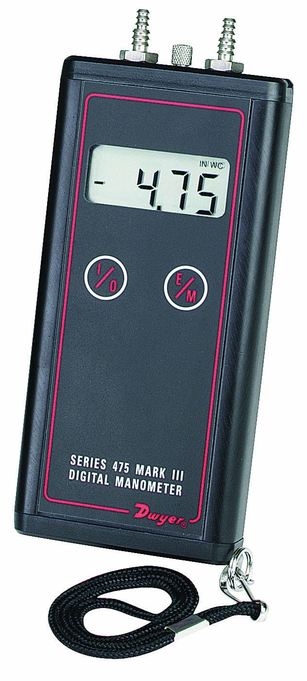
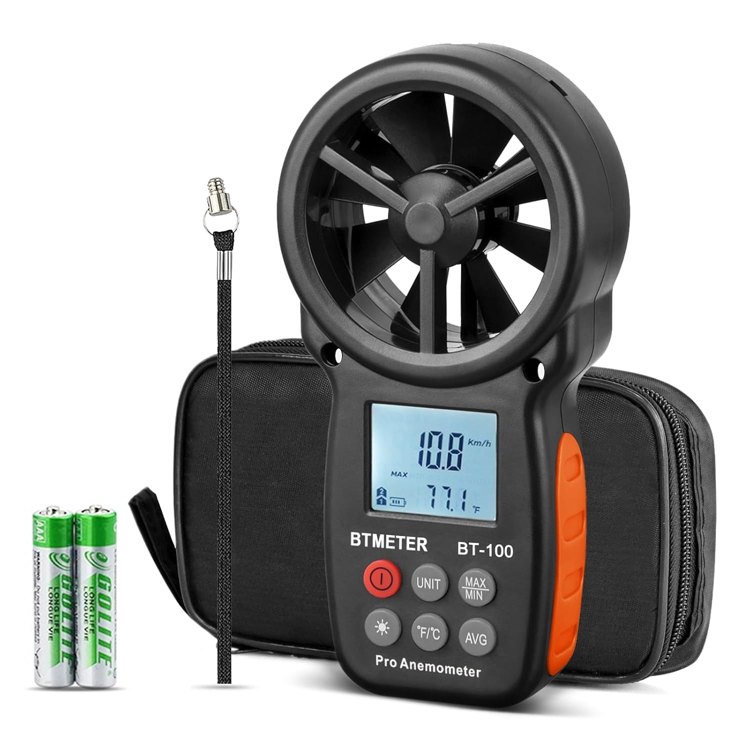
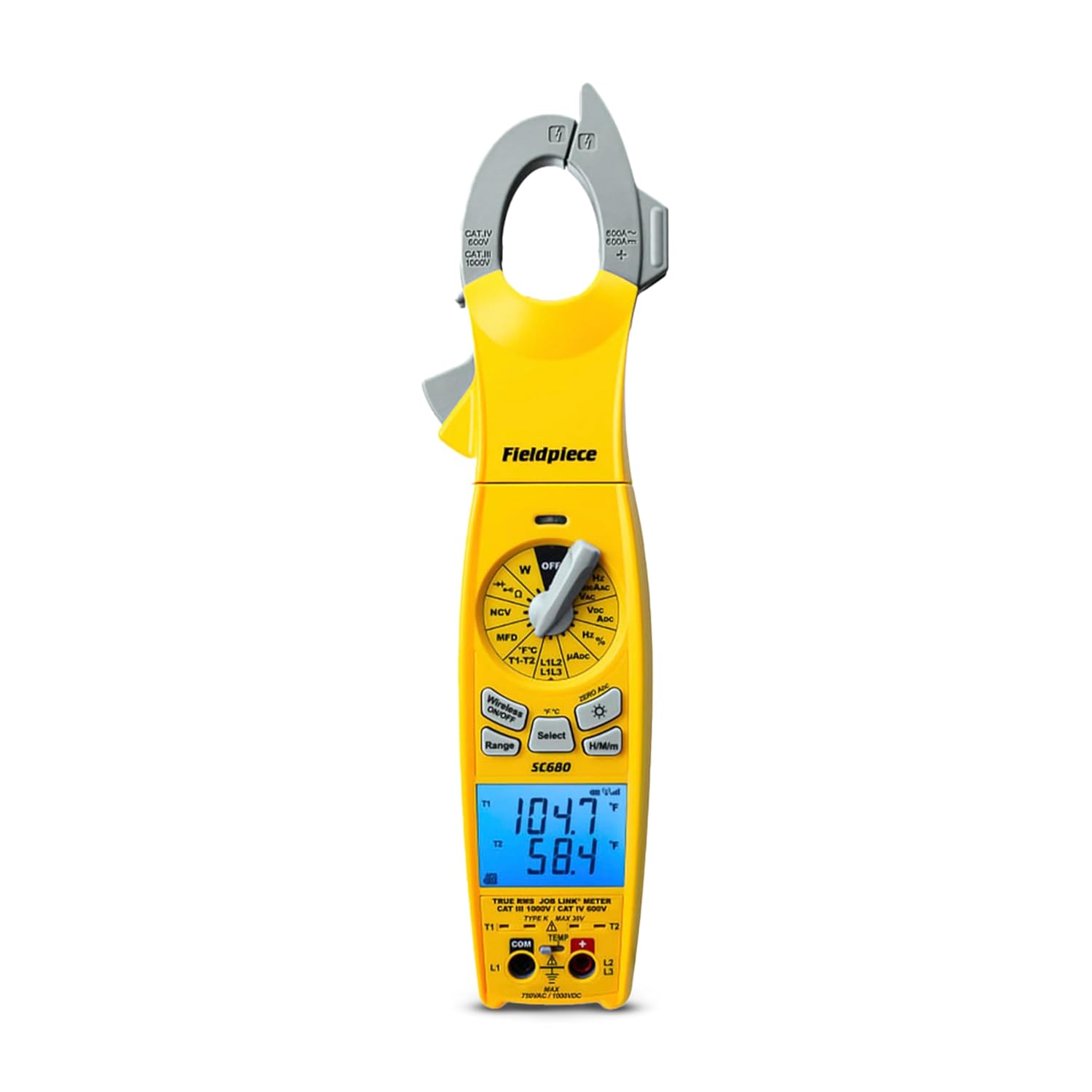
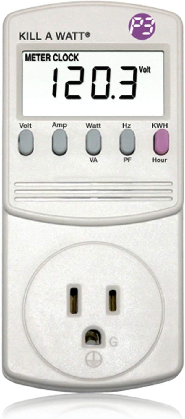
As an Amazon Associate, TestTalkHQ earns from qualifying purchases. Prices and availability can change.
Here are the fan laws as Twin City Fan & Blower prints them in its Engineering Resource Guide, with subscript 1 meaning the conditions you have and subscript 2 the conditions you want:
| Law | Equation | In words | Speed up 10 percent |
|---|---|---|---|
| 1. Airflow | CFM2 = (RPM2/RPM1) × CFM1 | Airflow follows speed, one for one | +10 percent |
| 2. Pressure | SP2 = (RPM2/RPM1)2 × SP1 | Static pressure follows the square of speed | +21 percent |
| 3. Power | BHP2 = (RPM2/RPM1)3 × BHP1 | Brake horsepower follows the cube of speed | +33 percent |
That last column is not our arithmetic — it is New York Blower’s, written out in Engineering Letter 5: “According to the fan laws, if the fan speed is increased 10% for a given system, the flow through the system will increase 10%, the system resistance will increase 21%, and the fan BHP will increase 33%.” Greenheck adds the companion warning from the other end of the range: “A 25% increase in rpm results in a 95% increase in horsepower. Considering this, initial fan selections should be sized with motor horsepowers greater than necessary if any increase in fan rpm is likely in the future.”
Two sentences that are easy to skim past and worth stopping on. The first is New York Blower’s: “The fan laws cannot be applied selectively, only simultaneously.” You do not get to take the extra airflow and leave the extra pressure and power behind. The second is Greenheck’s framing of what a fan law actually is: “we are not changing the system, only increasing fan speed. Therefore, we must remain on the system resistance curve.” Everything on this page depends on that.
A calculator is only worth trusting if it reproduces the examples its own sources print. These three come from three different manufacturers, and this page returns all three to the digits they published.
| Source | Starting point | The change | Published answer | This page |
|---|---|---|---|---|
| Twin City ERG100, p. 3 | 33,120 CFM at 2.5 in. SP, 620 RPM, 20.01 BHP | Raise to 41,500 CFM | 777 RPM, 3.93 in. SP, 39.39 BHP | 777 RPM, 3.93 in., 39.37 BHP |
| Greenheck Fan Fundamentals, p. 132 | 1,000 CFM at 0.25 in. Ps, 700 rpm | Raise to 2,000 CFM | 1,400 rpm, 1.0 in. Ps | 1,400 RPM, 1.000 in. |
| New York Blower, Engineering Letter 5 | Any fan on any fixed system | Speed up 10 percent | +10 percent flow, +21 percent resistance, +33 percent BHP | ×1.100, ×1.210, ×1.331 |
The Twin City example is the one worth reading to its conclusion, because the source does not stop at the arithmetic. Having found 777 RPM and 39.39 BHP, it says: “The new performance increases the fan’s horsepower requirement from 25 HP to 50 HP. If the fan is sped up to 777 RPM the motor must be resized.” A 25 percent airflow increase doubled the motor. And it closes with the instruction this page turns into an input of its own: “IMPORTANT NOTE: The new RPM should be checked to make sure it does not exceed the maximum allowable RPM for the fan that is installed.”
Two different curves get confused constantly, and the confusion is behind most misapplied fan law calculations.
The fan runs where the two cross, and nowhere else. The fan laws move the fan curve while holding the system curve still, which is exactly why they predict the new operating point so precisely — and exactly why they stop being true the moment the duct changes.
It is also why fan law 2 and the system curve equation are the same statement. Speed up 10 percent, airflow rises 10 percent, and the system demands 1.12 = 1.21 times the pressure. The fan supplies 1.21 times the pressure. They are not two coincidentally matching rules; they are one relationship written from either end, which is why this page prints the cross-check in the working numbers and why it always agrees.
There is a third thing that puts a fan off its published performance, and it is neither the fan nor the duct. New York Blower’s Engineering Letter 5 is entirely about it, and names four causes:
| Cause | What it looks like | What it costs |
|---|---|---|
| Eccentric flow into the fan inlet | An elbow landing straight on the inlet, a cramped inlet box | Uneven loading of the wheel; the published pressure never appears |
| Spinning flow into the fan inlet | Two elbows in different planes, a tangential entry, a cyclone upstream | Spin with rotation cuts capacity; spin against it raises BHP and noise |
| Improper ductwork at the fan outlet | No outlet duct, or a turn immediately at the discharge | Omitting the outlet duct costs half an outlet velocity pressure |
| Obstructions at the fan inlet or outlet | A fan sitting in a plenum, a big sheave in front of a double inlet, a cone stack cap | A stack cap alone can cost a full velocity pressure |
The reason this matters on a fan law page is the sentence New York Blower attaches to it: these losses “cannot be measured or even detected with field instruments because they are, in fact, a destruction of the fan performance characteristics.” They do not show up as extra static pressure on your manometer. They show up as a fan that will not make its numbers and nobody can see why.
The letter is blunt about the price of fixing it with speed: an inlet box, even with all its turning vanes installed, “could still easily represent losses of 10% to 15% of the required flow”, and recovering 10 percent costs 33 percent more power — “an obvious waste of energy due to an often avoidable system-related deficiency.”
Every manufacturer rating table is printed for standard air. Twin City defines it precisely: “dry air at 70°F at sea level (29.92 Hg barometric pressure)… equal to 0.075 lb./ft3 density.” New York Blower states the same figure independently.
Real air is frequently nowhere near that, and a fan responds to density in a very specific way. A fan is a constant-volume machine: it shifts the same cubic feet per minute whatever the air weighs, because the wheel sweeps the same volume per revolution. But static pressure and brake horsepower both scale directly with density. Thin air, same CFM, less pressure, less power.
The correction factor is simply the ratio of your air density to the standard 0.075. Twin City publishes it as a 276-cell chart of air temperature against altitude, and the whole chart is one expression — the absolute temperature ratio times the barometric pressure ratio:
| Air temperature | Sea level | 2,000 ft | 5,000 ft | 7,000 ft | 10,000 ft |
|---|---|---|---|---|---|
| 0°F | 1.152 | 1.071 | 0.959 | 0.889 | 0.792 |
| 70°F (standard) | 1.000 | 0.930 | 0.832 | 0.772 | 0.688 |
| 100°F | 0.946 | 0.880 | 0.787 | 0.730 | 0.651 |
| 150°F | 0.869 | 0.808 | 0.723 | 0.671 | 0.598 |
| 200°F | 0.803 | 0.747 | 0.668 | 0.620 | 0.552 |
| 300°F | 0.697 | 0.648 | 0.580 | 0.538 | 0.480 |
| 500°F | 0.552 | 0.513 | 0.459 | 0.426 | 0.380 |
Read the 70°F row across and you have the altitude story on its own: Denver, at 5,280 ft, runs at about 82 percent of sea-level density before anybody has heated the air. Read the sea-level column down and you have the temperature story: a furnace supply fan handling 150°F air is working in air at 87 percent of standard density.
Twin City gives the three rules that follow, and this page applies all three:
The fan laws tell you what speed you need. Getting there is a separate mechanical question with three answers.
| Method | How the speed changes | Where it fits | Catch |
|---|---|---|---|
| Belt drive sheave | Fan RPM = motor RPM × motor sheave pitch diameter ÷ fan sheave pitch diameter. Leave the fan sheave alone and the motor sheave scales with the speed ratio directly. | Most commercial air handlers and almost all older equipment | Sheaves come in discrete sizes; belt length changes with the ratio; an adjustable sheave gives a range but needs setting and locking |
| Motor speed taps | A multi-speed PSC motor has fixed taps, typically three or four. You get the tap, not a number you chose. | Residential direct-drive furnaces and air handlers | Coarse steps; moving up a tap can overshoot and lift static pressure and noise more than you wanted |
| Variable frequency drive | Speed follows frequency, so a percentage of base speed is a percentage of 60 Hz. | Anything three-phase; the standard answer on commercial retrofits | Motor cooling falls with speed on a shaft-mounted fan; low-speed operation needs an inverter-duty motor and attention to bearing currents |
The belt-drive case is the one this page does the arithmetic for, because it is the one where a wrong number means buying the wrong part. If the fan sheave is untouched, the required motor sheave is just the present one multiplied by the speed ratio — a 2.8 in pitch diameter at a ratio of 1.167 becomes 3.27 in. Buy the nearest standard size and come back to this page with the speed it actually produces, because that step may be 3 percent either way and 3 percent of speed is 9 percent of power.
The results panel reports a fan static efficiency you did not enter. It is computed from your own four baseline numbers using Twin City’s published definition:
SE = CFM × SP × 100 ÷ (6356 × BHP)
Its job is to catch bad input before you act on the output. If your measured airflow, static pressure and power imply an efficiency above 100 percent, the fan is producing more air power than it consumes, which it is not — one of the four numbers is wrong. In practice it is almost always the power, because amps times volts was used where true watts was needed; on an induction motor the power factor can be 0.6 or lower and that route reads high, which makes the computed efficiency read low. Reading implausibly high usually means the static pressure was taken with the filter out, or the airflow figure came from a nameplate.
The other thing it tells you is structural: a speed change leaves the efficiency exactly unchanged. That is not a coincidence, it is the assumption. Airflow times pressure is the ratio cubed, and power is the ratio cubed, so they cancel. The fan laws hold the fan at one point on its own efficiency curve, and that is the whole reason they are allowed to be this simple.
Several things a fan calculator could appear to offer are not derivable from these sources, so they are not here.
What are the three fan laws? For one fan on one unchanged system at one air density: airflow varies directly with fan speed, static pressure varies with the square of fan speed, and brake horsepower varies with the cube of fan speed. Twin City Fan & Blower prints them as CFM2 = (RPM2/RPM1) × CFM1, SP2 = (RPM2/RPM1)2 × SP1 and BHP2 = (RPM2/RPM1)3 × BHP1, and Greenheck prints the identical three relationships in its Fan Fundamentals guide. New York Blower adds that they cannot be applied selectively, only simultaneously — you do not get the extra airflow without the extra pressure and the extra power.
If I speed a fan up 10 percent, how much more power does it use? About 33 percent more. New York Blower states it directly: a 10 percent speed increase gives 10 percent more flow, 21 percent more system resistance and 33 percent more fan brake horsepower, because 1.13 = 1.331. This is the single most misunderstood number in fan work, and it is why a modest airflow increase so often means a new motor as well as a new drive.
How do I work out the RPM I need for a target CFM? Multiply the present fan speed by the ratio of the target airflow to the present airflow. Greenheck prints it as rpm2 = rpm1 × (cfm2/cfm1) and works the example: a fan at 700 rpm delivering 1,000 cfm at 0.25 in. needs 1,400 rpm for 2,000 cfm, at which point the static pressure has risen to 1.0 in. The present airflow must be a measured figure on the system you are actually scaling, not a nameplate value.
Do the fan laws still work if I change the ductwork? No, and that is the most common way they get misapplied. The fan laws move the fan curve while the system curve stays put, which Greenheck states as remaining on the system resistance curve. Change the filter, the coil, a damper, a length of duct or a register and the system curve moves, so a calculation scaled from measurements taken before the change describes a system that no longer exists. Measure the new baseline and start again.
What size motor sheave do I need to reach a new fan speed? Fan speed equals motor speed multiplied by the motor sheave pitch diameter divided by the fan sheave pitch diameter, so with the fan sheave unchanged the required motor sheave pitch diameter is the present one multiplied by the speed ratio. A 2.8 in pitch diameter sheave at a speed ratio of 1.167 becomes 3.27 in. Use pitch diameter rather than outside diameter, and note that standard sheaves come in steps, so you will land near the target rather than on it — recheck the speed after fitting, because a 3 percent speed error is a 9 percent power error.
Why does my fan move less air at altitude? It does not move less air. A fan is a constant-volume machine, so it still shifts the same cubic feet per minute — but the air weighs less, so it develops proportionally less static pressure and draws proportionally less power, and it delivers less mass of air, which is what actually carries heat. At 5,000 ft the correction factor is 0.832, so the same fan at the same speed makes 83 percent of its sea-level static pressure. If the job needs the pressure, the fan has to turn faster, and that follows the square law.
What is standard air density? Dry air at 70 degrees Fahrenheit at sea level, 29.92 inches of mercury barometric pressure, weighing 0.075 pounds per cubic foot. Twin City and New York Blower both state it in those terms, and every published fan rating table is built on it. The correction factor for any other condition is simply the operating density divided by 0.075, which is the absolute temperature ratio times the barometric pressure ratio.
What is cold-start brake horsepower, and why does it matter? It is the power the fan absorbs in cold, dense air at the site elevation, as opposed to the hot, thin air it will settle into. Twin City gives it as the brake horsepower at standard density multiplied by the correction factor at the required elevation and 70 degrees Fahrenheit. In their example the fan absorbs 8.96 BHP running at 300 degrees Fahrenheit but 12.87 BHP starting cold at the same altitude. Size the motor on the running figure and it will fail on a winter morning start.
Can I just use a bigger sheave to fix low airflow? Sometimes, and only after checking three things the fan laws do not know about. First, whether the motor can take the cubed power increase, including its service factor. Second, whether the new speed stays under the cataloged maximum safe speed for the wheel — New York Blower states that the fan speed should never be increased beyond it. Third, whether the airflow problem is actually the fan at all; if the static pressure is high because of a crushed flex duct or a loaded filter, speeding the fan up buys expensive noise and fixes nothing.
Why does slowing a fan down save so much energy? Because the cube law runs both ways. Dropping to 80 percent speed drops power to 0.83 = 51 percent, roughly halving it for a fifth less airflow. That asymmetry is the entire argument for variable-speed control over damper throttling: a damper adds resistance and moves the operating point up the fan curve, where the fan is still working hard, while reducing the speed moves the whole fan curve down and the power follows the cube.
Does a VFD change the fan laws? No. A variable frequency drive is just a way of setting the speed, and a fan on a drive follows the same three laws as a fan on a sheave. What a drive changes is what else you have to think about: motor cooling falls with speed on a shaft-mounted cooling fan, so continuous low-speed running wants an inverter-duty motor, and the drive itself has losses of a few percent. The arithmetic of airflow, pressure and shaft power is unchanged.
Do the fan laws apply to an ECM blower? Only if you are setting its speed. An electronically commutated motor running in constant-airflow mode deliberately does the opposite of what the fan laws describe: it varies its own speed to hold a programmed CFM as static pressure changes, so speed is an output rather than an input. The laws still govern the underlying machine — the ECM is paying the cube-law power cost of the speed it has chosen, which is why a constant-airflow blower in a restrictive duct draws so much more wattage — but you cannot use them to predict what it will do. Program the airflow table entry instead.
What is the difference between static pressure and total pressure for fan calculations? Static pressure is the potential energy of the airstream, acting equally in all directions; total pressure is static plus velocity pressure, which is the energy in the air’s motion. Twin City prints TP = SP + VP and VP = (V/1096.7)2 × density, which at standard density reduces to (V/4005)2. Velocity pressure needs the air velocity at the fan outlet, which needs the outlet area — a catalog dimension. Field static pressure readings are static, which is why this page works in static pressure and computes static rather than mechanical efficiency.
What is a fan service factor and can I use it? The service factor is a multiplier on motor nameplate horsepower that the motor manufacturer permits continuously, commonly 1.15 on open drip-proof motors, printed on the nameplate as SF. It is real headroom, so running at 1.1 times nameplate on a 1.15 SF motor is within specification. It is also heat: a motor in its service factor runs hotter and insulation life falls sharply with temperature. Treat it as a ceiling that must not be crossed rather than capacity you plan to use, and if a selection only fits by using it, pick the next motor up.