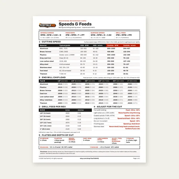
Machining Speeds & Feeds Card
One page. Speeds, chip load and drill feed, imperial and metric.
$3.99
BuyFeed rate and chip load per tooth — solve either direction from RPM and flute count
Enter spindle RPM, number of flutes, and either a target chip load to get feed rate (IPM), or your current feed rate to see actual chip load per tooth. Includes a reference chip-load table by material and tool diameter. SFM sets RPM; chip load sets feed at that RPM.
Need full SFM, RPM, and MRR? Use the Milling Speed and Feed Calculator. Read the Chip Load Guide for symptoms, rigidity factors, and CNC programming pitfalls.

One page. Speeds, chip load and drill feed, imperial and metric.
$3.99
Buy
27 pages. Milling, drilling, tapping, turning and CNC routing.
$12.99
Buy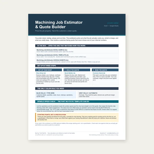
Quote shop work and check operations against your spindle's top speed.
Excel or Google Sheets. Best on a computer.
$29.00
Buy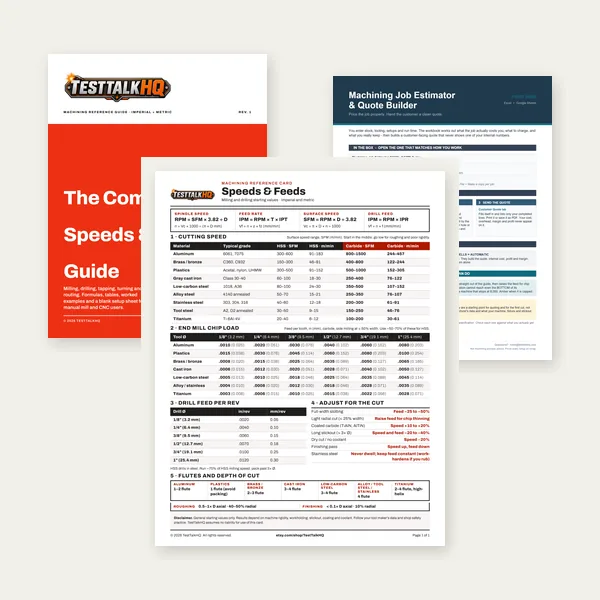
Card, 27-page guide and the estimator workbook. All six files.
Excel or Google Sheets. Best on a computer.
$34.99
$45.98 if bought separately — save $10.99
BuyCheckout opens in a new tab.
Carbide end mills for the IPT ranges on this page, plus measurement and Drilling / Machining catalog picks for setup and hole prep

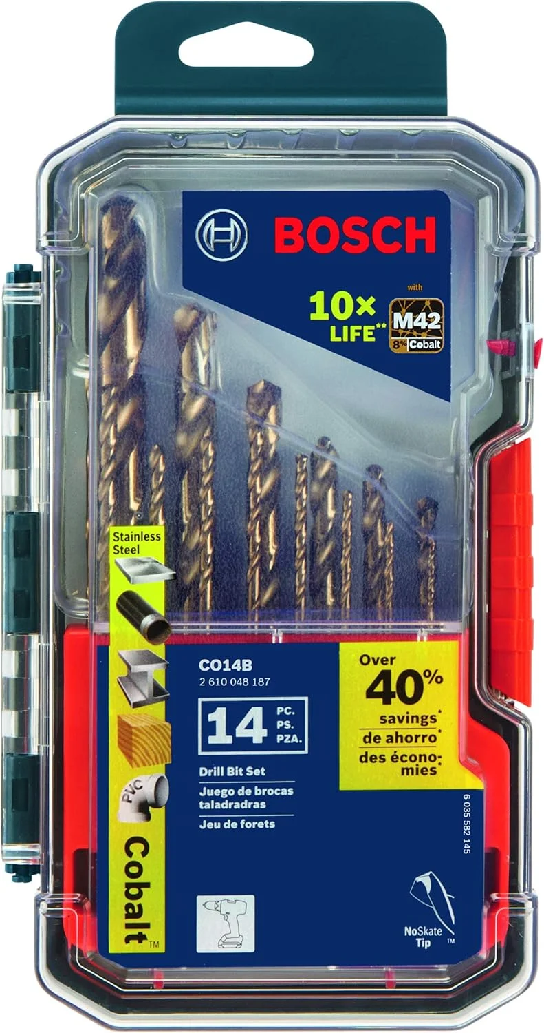
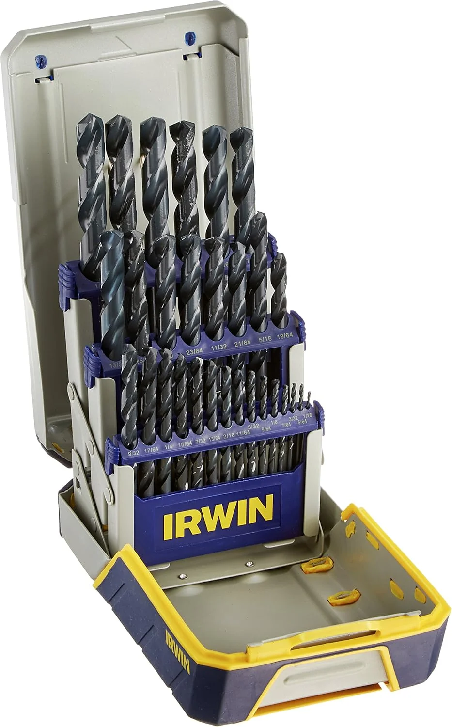

As an Amazon Associate, TestTalkHQ earns from qualifying purchases. Drilling / Machining had only two drill-bit SKUs before this end-mill set was added — remaining cards use Measurement and Shop Supplies picks that support chip-load setup.
Surface feet per minute (SFM) tells you how fast the cutting edge moves through the material — it drives spindle RPM based on cutter diameter. Chip load (feed per tooth, IPT) tells you how thick each chip is — it drives table feed rate based on RPM and flute count. You need both: first set RPM from SFM and diameter, then set feed from chip load, flutes, and that RPM. Running the right RPM with the wrong feed still produces rubbing or broken tools.
The Milling Speed and Feed Calculator handles the full SFM-to-RPM-to-feed chain when you are starting from material and cutter size. This calculator focuses specifically on the feed-rate side — either converting a target chip load into IPM, or checking what chip load your current feed actually produces.
Select your workpiece material and enter tool diameter to highlight the recommended chip-load range in the table. These values assume carbide end mills in a reasonably rigid setup. Aluminum allows roughly double the chip load of mild steel; stainless runs about 60% of steel values. Smaller diameters need proportionally thinner chips — a 1/8-inch end mill cannot run the same IPT as a 1/2-inch cutter without snapping.
Click a highlighted range as your starting point, then increase feed until chips look right: curled and consistent in steel, large shiny curls in aluminum, short tight curls in stainless. If you hear squealing or see powder, chip load is too low. If the tool chatters or chips are thick and blue, it is too high.
Too low a chip load causes rubbing instead of shearing — the edge skids across the workpiece, generating heat without efficient material removal. Signs include squealing, fine powder chips, rapid edge dulling, work hardening on stainless, and built-up edge on aluminum. Operators often slow feed to "be safe," which makes the problem worse.
Too high a chip load overloads the flute, causes deflection and chatter, and can chip or break carbide instantly. Signs include loud chatter, rough finish, broken corners, and blue or purple chips in steel. Full-width slotting and long tool stick-out require reducing chip load below chart values even when RPM is correct.
Textbook chip loads assume a rigid machine, short tool stick-out, and moderate radial engagement. Real shops violate those assumptions constantly. Reduce chip load 20–40% on manual mills with backlash, when using HSS instead of carbide, when slotting full width, when depth of cut exceeds half the cutter diameter, or when tool stick-out exceeds three times the diameter. CNC programs that use high-efficiency milling (small radial engagement, full axial depth) can often run higher feed rates because chip thinning keeps actual chip thickness manageable — but that is a CAM strategy, not a reason to ignore chip load on conventional toolpaths.
Chip welding, breakage from chip thinning, poor finish, premature wear, or charts that do not match: Chip Load Troubleshooting. Climb vs conventional (chip formation & machine risk): Climb vs Conventional Milling.