Voltage Drop Troubleshooting

Diagnose when measured drop fights the calculator, equipment underperforms despite a “passing” calc, long feeds still sag, multi-wire branch mistakes hide imbalance, and meters lie about where you probe

Not another how-to for V = I × R. Pair this page with the Advanced Voltage Drop Calculator when paper numbers look fine and the job still fails. For definition and formula walkthroughs use Voltage Drop Explained and How to Calculate Voltage Drop — this guide stays on diagnosis.

Diagnosing a flexible cord run? Start with the extension cord voltage drop guide, then test the actual AWG, length, and load with the extension cord voltage drop calculator.

Voltage Drop Problems Quick Answer

Use this when the lights dim, a motor stalls, or your DMM reading refuses to match the spreadsheet.

ProblemWhat it usually meansFirst fixNext tool
Measured drop >> calculatedExtra resistance not in the model — loose lugs, corroded Al, wrong gauge actually pulledIR / torque check terminations; verify AWG with mic/strip and panel scheduleAdvanced VD Calculator
Calc “passes” but equipment diesCalc used wrong current (nameplate, not inrush), ignored heat/ambient, or shared-neutral shiftRe-run at locked-rotor / peak amp; check ambient derate & MWBC loadingVD vs Ampacity
Long shop / pump / generator feed still sagsOne-way length entered as total, Al resistivity ignored, or feeder+branch stackedUse one-way feet × 2 for copper/Al formulas; model feeder then branchLong Runs Guide
One MWBC leg bright, other dull / odd NECsShared neutral overloaded or open; phases unbalancedClamp neutral & each hot under load; never share neutrals across different multiwire systems carelesslyNEC VD Notes
Panel looks fine, receptacle dies under loadYou measured source, not load end — or measured unloadedProbe hot–neutral at load while running; compare to panel hot–neutral same phaseHow to Calculate VD
Good voltage, tripped breaker / heat smellAmpacity / connection failure, not volt-drop mathStop chasing %VD — thermal path & torque firstVD vs Ampacity
Diagnose in 60 seconds: (1) load the circuit to real current, (2) measure line-to-neutral (or line-to-line) at the load and at the source on the same phase, (3) subtract for measured drop, (4) compare to calculator using the same amps and one-way length. If measured is much worse, hunt hardware resistance before you upsizing another AWG on paper.

1. Measured Voltage Drop Doesn’t Match the Calculator

What it looks like: Spreadsheet or the advanced calculator says ~2–3% on the design gauge. Under load your meter shows 6–10% at the receptacle, well pump, or welder outlet. Idle voltage looks almost normal.

Why it happens (extra R the formula never saw): Textbook drop is I × Rconductors. Real drop is I × (Rcopper/Al + Revery lug, splice, breaker, receptacle, and oxidised connection). Any series contact resistance that was ignored in the model shows up as “mystery” volts once current flows.

Likely causes checklist:

  • Loose set-screw or under-torqued lug — especially Al terminations and service/neutral bars. Heat cycles loosen them; resistance climbs without changing AWG.
  • Corroded aluminium or outdoor/marine terminations — white oxide and moisture raise contact R. Copper–Al mixes without listed connectors and inhibitor compound.
  • Wrong gauge actually installed — scheduled as 6 AWG, pulled as 8; or mixed colours left unmarked in long conduits. Strip and measure OD / read printing.
  • Undersized or shared neutral not in the model — calculator assumed dedicated return; field circuit returns on a skinny multiwire neutral.
  • Breaker / fuse holder / pin-and-sleeve contact resistance — source-side voltage healthy; load sees drop across a warm enclosure.

Fixes:

  • De-energise safely and retorque to manufacturer values; look for discoloration, fretting, or melted plastic behind devices.
  • On Al, clean, use listed connectors, and apply anti-oxidant where the listing requires it (Noalox-class inhibitor is common in those kits).
  • Verify conductor size against the schedule and the print on the jacket — then re-run the calculator with actual AWG.
  • Measure millivolt drop across suspect joints under load with a quality True-RMS meter when safe — high mV drop on a tight length of conductor is a contact story, not an ampacity chart story.
Misdiagnosis: Do not “fix” a contact problem by upsizing the entire run first. If lug resistance is the villain, bigger wire still lands on the same burned set-screw.

2. Circuit / Equipment Fails Even Though the Calc “Passes”

What it looks like: NEC-flavoured 3% / 5% recommendation is green on paper. Compressors hard-start, VFD trips on undervoltage, LED drivers flicker on tip-up cycles, welders bog only when other loads share the feeder.

What the calculator is not doing for you:

  • Inrush / locked-rotor amps — steady-state FLC may pass; motors draw multiple × FLC at start. Voltage collapses for a few cycles and the starter “chatters” or the drive protects.
  • Ambient / conductor temperature — hot attics and rooftops raise copper resistance (~0.4%/°C). Design calc often uses 75°C table R without field heat.
  • Harmonics / non-linear current — True-RMS current is higher than a cheap meter’s average sensing; electronic loads heat neutrals on MWBCs.
  • Shared neutrals and return paths — single-phase model ignores how return current shifts line-to-neutral volts on the weak leg.
  • Source stiffness — generator, soft utility, or heavily loaded transformer adds source impedance the branch calc never includes.

Fixes:

  • Re-run voltage drop at a realistic peak or start amp, not just nameplate continuous. Soft-starts / VFDs change the amp profile — still verify DC bus / undervoltage trip thresholds.
  • Separate ampacity derating from voltage drop; both must pass. Use Voltage Drop vs Ampacity when the conflict is heat vs resistance.
  • Measure source voltage under the same load condition as the load. A soft primary makes every “passed” branch calc look wrong at the tool.
Field rule: Change one variable at a time — peak amps in the calc, then source voltage, then connection R. Multiplying upsides hides which layer failed.

3. Long-Run Feeds Still Sag (Generators, Wells, Detached Shops)

What it looks like: Detached garage welder, barn pump, or generator transfer still brown-outs even after “we upsized.” Spreadsheet used 200 ft when the trench is 200 ft one-way — or Al feeders were treated like copper.

Common field errors unique to long work:

  • Entering round-trip length when the formula already multiplies by 2 (or vice versa).
  • Ignoring Al resistivity (~1.6× copper) on USE-2 / URD / multiplex.
  • Sizing only the final branch while the underground feeder eats most of the budget — stack feeder + branch in the advanced calculator’s combined mode.
  • Generator AVR struggling: voltage at the panel looks OK unloaded, collapses under large step loads.

Fixes:

  • Model feeder and branch separately; keep total within your design target (informational NEC notes cite ~3% branch / ~5% feeder+branch — verify with AHJ).
  • For wells / irrigation, include motor start amps and elevation if control boards are voltage-sensitive.
  • After upsizing, re-check conduit fill and ampacity derating — larger wire solves drop and can re-break bundling math. Details: long-run sizing guide.

4. Multi-Wire Branch Circuit Voltage Drop Mistakes

What it looks like: One countertop leg runs heaters fine; the other flats out or trips GFCI/AFCI. Neutral feels hot. Line-to-neutral volts unequal under load though both “circuits” share a handle-tied breaker.

Why MWBC math bites voltage drop: On a proper 240/120 MWBC, return currents partially cancel in the shared neutral. If phases land on the same leg, or a multiwire pair is broken into two unrelated circuits, the neutral carries more than the model assumed. Calculators that treat each 120 V circuit as an independent round-trip overcount or undercount depending on how you entered the neutral.

Likely causes:

  • Both ungrounds on the same phase (no 240 V potential, doubled neutral current).
  • Open or high-resistance shared neutral — line-to-neutral balloons on one leg (dangerous for appliances).
  • Treating MWBC as two full L–N–L loops in software without reflecting cancellation.

Fixes:

  • Verify opposite phases on a two-pole breaker; clamp neutral under simultaneous load.
  • Never land mixed MWBC neutrals on a single-pole discontinuity without a bonded handle and proper identification.
  • When diagnosing, measure each L–N at the load and L–L at the source — open-neutral signatures look like “voltage drop” until you see >120 V on one leg unloaded.
Safety: Open neutral on an MWBC can put 200+ V across 120 V gear. Treat unequal L–N readings as a wiring fault first, not an AWG upsizing opportunity.

5. Where to Measure — and How Meters Lie

What it looks like: “We checked voltage — it’s fine.” Probe was at the panel with tools plugged in far away, or measured unloaded receptacles. Calc and field numbers will never reconcile.

Correct differential method:

  • Energise the real load (rated tool, heater, motor).
  • Measure Vsource at the supplying breaker or feeder lugs (same phase).
  • Measure Vload at the equipment terminals or receptacle under that same load.
  • Drop ≈ Vsource − Vload. Percentage = drop / nominal (or / Vsource, be consistent).

Common measurement mistakes:

  • Probing hot-to-ground instead of hot-to-neutral on 120 V circuits (misses neutral drop).
  • Using an averaging meter on distorted waveforms — True-RMS matters for VFDs / welders.
  • Long meter leads inductive kick; hold probes steady; don’t compare different meter brands without a sanity check.
  • Recording panel voltage after the load staged off — soft sources recover and hide the sag.

Related how-to: formula and percent method live in How to Calculate Voltage Drop; code notes in NEC Voltage Drop Requirements.

Decision: Fix Drop, Fix Ampacity, or Both?

Undervoltage that clears when you upsize is a resistance problem. Heat, smell, breaker trips on continuous load with decent voltage are often ampacity / termination problems. Run both calcs — the larger conductor wins. Full walkthrough: Voltage Drop vs Ampacity.

Open Advanced Voltage Drop Calculator →

Electrical

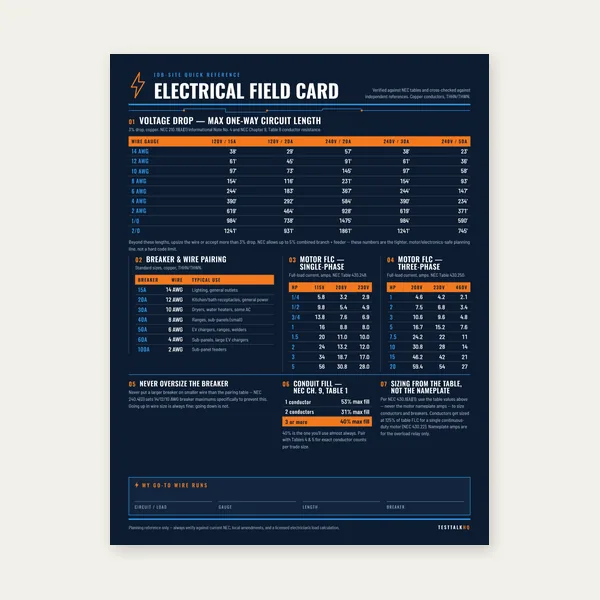
Electrical Reference Card

Electrical Reference Card

One page. Voltage drop lengths, breaker and wire pairing, motor FLC.

$3.99

Buy

Complete Electrical Reference Guide

Complete Electrical Reference Guide

15 pages. Ampacity, corrections, voltage drop, motor circuits, conduit fill.

$12.99

Buy
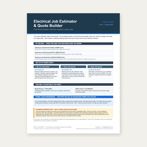
Electrical Job Estimator

Electrical Job Estimator

Quote electrical work and flag panel headroom before you price it.

Excel or Google Sheets. Best on a computer.

$29.00

Buy

BEST VALUE
Electrical Complete Bundle

Electrical Complete Bundle

Card, 15-page guide and the estimator workbook. All six files.

Excel or Google Sheets. Best on a computer.

$34.99

$45.98 if bought separately — save $10.99

Buy

See all Electrical products

Checkout opens in a new tab.

Tools for Diagnosing Real Voltage Drop

Six electrical picks from the TestTalkHQ affiliate catalog — meters, clamp, fish tape, stripper, and anti-oxidant for aluminium terminations

Ideal Industries 61-757 clamp meter

Ideal Industries 61-757 Clamp Meter

  • Confirm running / start amps
  • True RMS current for the calc
  • Clamp neutrals on MWBCs
View on Amazon →
Klein Tools MM420 multimeter

Klein Tools MM420 Digital Multimeter

  • Auto-ranging TRMS backup meter
  • Everyday receptacle / panel checks
  • Solid second tool for helpers
View on Amazon →
Greenlee stainless fish tape

Greenlee FTSS438-200 Fish Tape

  • Long pulls after upsizing
  • 200 ft stainless tape
  • Shop / trench conduit runs
View on Amazon →
Klein Tools 11047 wire stripper

Klein Tools 11047 Wire Stripper

  • Verify / prep correct AWG
  • Clean strips for good terminations
  • 10–18 AWG shop staple
View on Amazon →
Ideal Noalox anti-oxidant compound

Ideal Noalox Anti-Oxidant

  • Al termination resistance control
  • Use with listed Al connectors
  • Cuts oxide-driven mystery drop
View on Amazon →

As an Amazon Associate, TestTalkHQ earns from qualifying purchases. Always follow manufacturer torque and listing requirements — compound is not a substitute for the correct connector.

Frequently Asked Questions

Why is my measured voltage drop higher than the calculator?

Extra series resistance — loose lugs, oxidised aluminium, wrong installed gauge, device contacts — is outside most conductor-only models. Fix terminations and verify AWG before more upsizing.

Can voltage drop pass and the motor still struggle?

Yes. Steady-state amp assumptions miss locked-rotor / start current, soft sources, and ambient heat. Re-run at peak amps and measure under start.

Where should I put the meter probes?

Compare source and load on the same phase under the same load. Hot-to-neutral (120 V) or line-to-line (240 V). Source-only checks miss the run.

Do multiwire branch circuits change voltage drop?

Yes. Shared neutrals and wrong phasing alter return current. Clamp the neutral and confirm opposite phases before trusting a single-phase round-trip model.

When do I upsize for drop vs ampacity?

Both floors apply independently; install the larger required gauge. Walkthrough: Voltage Drop vs Ampacity.

Are NEC 3% and 5% hard limits?

They are informational notes in many editions, not automatic Chapter 2 absolute mandates. Design to them for equipment performance; confirm your AHJ / project spec: NEC voltage drop notes.

General Ampacity Diagnosis

If the conductor, breaker, temperature column, neutral count, or final derated result still disagrees with the field, use Wire Ampacity Troubleshooting. Re-run the numbers with the Wire Ampacity & Derating Calculator and review the method in Wire Ampacity and Derating Explained.