Welding Wire Size Chart Guide: How to Choose the Right MIG Wire Diameter
Pick the wrong MIG wire diameter and thin sheet blows through—or thick plate stays cold and spattery. This page gives you a shop-floor quick chart (thickness → wire → amps → IPM), then the full breakdown: flux-core vs solid, contact tips, welder limits, and mistakes to avoid.
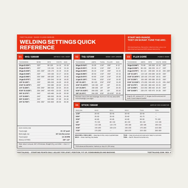
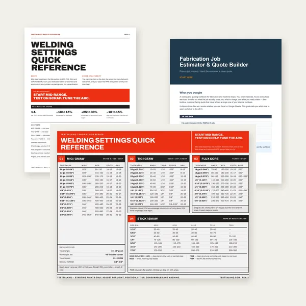
Ballpark starting points for short-circuit MIG with typical 75/25 or CO2 setups. Tune on scrap—machine charts, gun length, and joint type all move the window.
Material
Wire
Amps
IPM
Notes
24–22 ga (≤0.030″)
.023″
40–70
120–220
Lowest heat; spool gun or short gun helps feeding.
20–18 ga
.030″
50–90
100–180
Great for auto body / thin HVAC.
16 ga (0.060″)
.030″ or .035″
70–110
110–220
Overlap zone—.030″ if gaps or vertical.
14 ga
.035″
90–130
145–210
Typical fab “daily driver” thickness.
11 ga / 1/8″
.035″
110–160
175–260
Single-pass fillets common at mid-amps.
3/16″
.035″ or .045″
140–220
225–360
.045″ when you have stable 180A+ available.
1/4″
.045″
180–230
300–380
.035″ works multi-pass, slower.
3/8″+
.045″–.052″
220–300+
360–480+
Thick plate: verify on scrap; rule tapers at high current.
IPM ranges follow the same burn-off factors used in our wire feed speed guide (thickness in thousandths × factor by wire diameter). Your readout may differ—measure 6 seconds of feed with a ruler if in doubt.
Need the numbers, not the lecture?
Use the calculators below when you want settings, wire size, gas flow, or wire usage without guessing.
Wire diameter isn’t just how thick the electrode looks—it sets what you can weld, how fast you can deposit metal, and whether you get penetration or blow-through. Thinner wire (.023″–.030″) keeps 24-gauge sheet alive; thicker wire (.045″–.052″) lays down heavy plate in fewer passes. You can’t “turn down” a .045″ wire to act like .023″: the diameter itself sets a minimum stable heat band.
The Three Critical Effects of Wire Diameter
1. Amperage range (heat output)
Each diameter has a stable operating band:
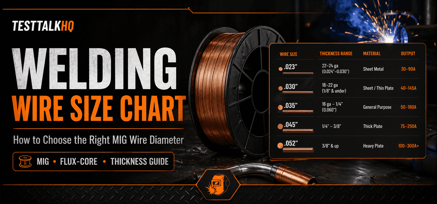
.023″ wire: 30–90 amps (thin materials)
.030″ wire: 40–145 amps (sheet through light structural)
.035″ wire: 50–180 amps (general fab)
.045″ wire: 75–250 amps (structural to heavy plate)
.052″ wire: 100–300+ amps (industrial heavy plate)
Running .045″ at 60 A gives a stubby, cold arc; .023″ at 200 A melts back into the tip.
2. Deposition rate
.030″ @ ~100 A: roughly 3–4 lb/hr
.035″ @ ~130 A: roughly 5–6 lb/hr
.045″ @ ~180 A: roughly 8–10 lb/hr
More deposition speeds thick work but drives more heat into thin sheet.
3. Penetration depth
.030″ @ 100 A: about 1/16″–3/32″ penetration (16–18 ga territory)
.035″ @ 100 A: about 3/32″–1/8″ (14 ga–1/8″)
.045″ @ 100 A: wrong band—too harsh for thin sheet, still light for thick plate
Real-world example: 1/8″ brackets
.030″ too small: may need 140+ A for fusion → burn-back, spatter, slow passes.
.045″ too large: stable arc wants ~120+ A → holes in thin spots, huge puddle.
.035″ right-sized: 110–140 A, controllable bead, good fusion.
Wire Sizes Explained (.023″ to .052″)
MIG wire comes in five common diameters, each aimed at thickness ranges and welder output.
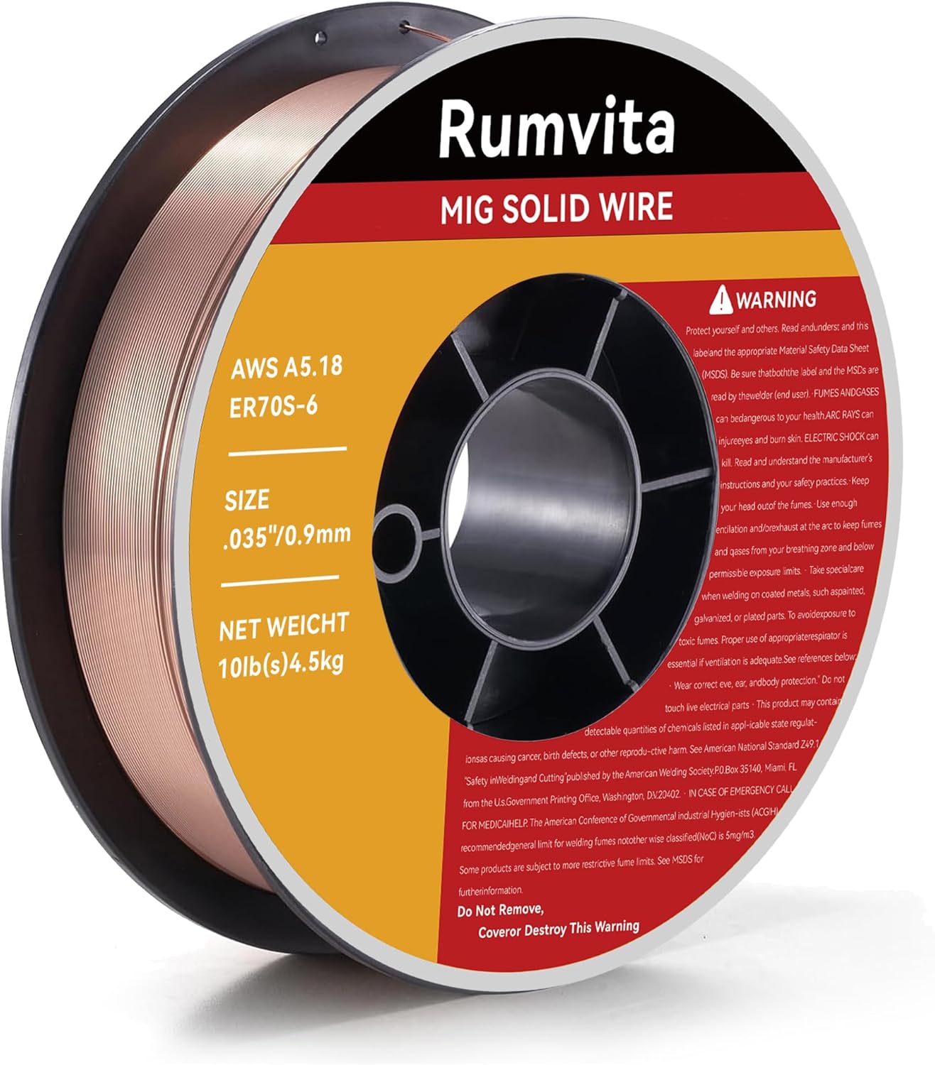
.023″ wire (0.6 mm) – ultra-thin sheet
Best for: 22–24 ga (0.024″–0.030″), auto body, HVAC, precision thin work.
Typical: 30–90 A; 120V machines and spool guns; 100% CO2 or 75/25.
Traits: very low heat; needs clean steel; often 200–400 IPM; short leads or spool guns.
Limits: about 1/16″ max practical; not every alloy; higher cost per lb.
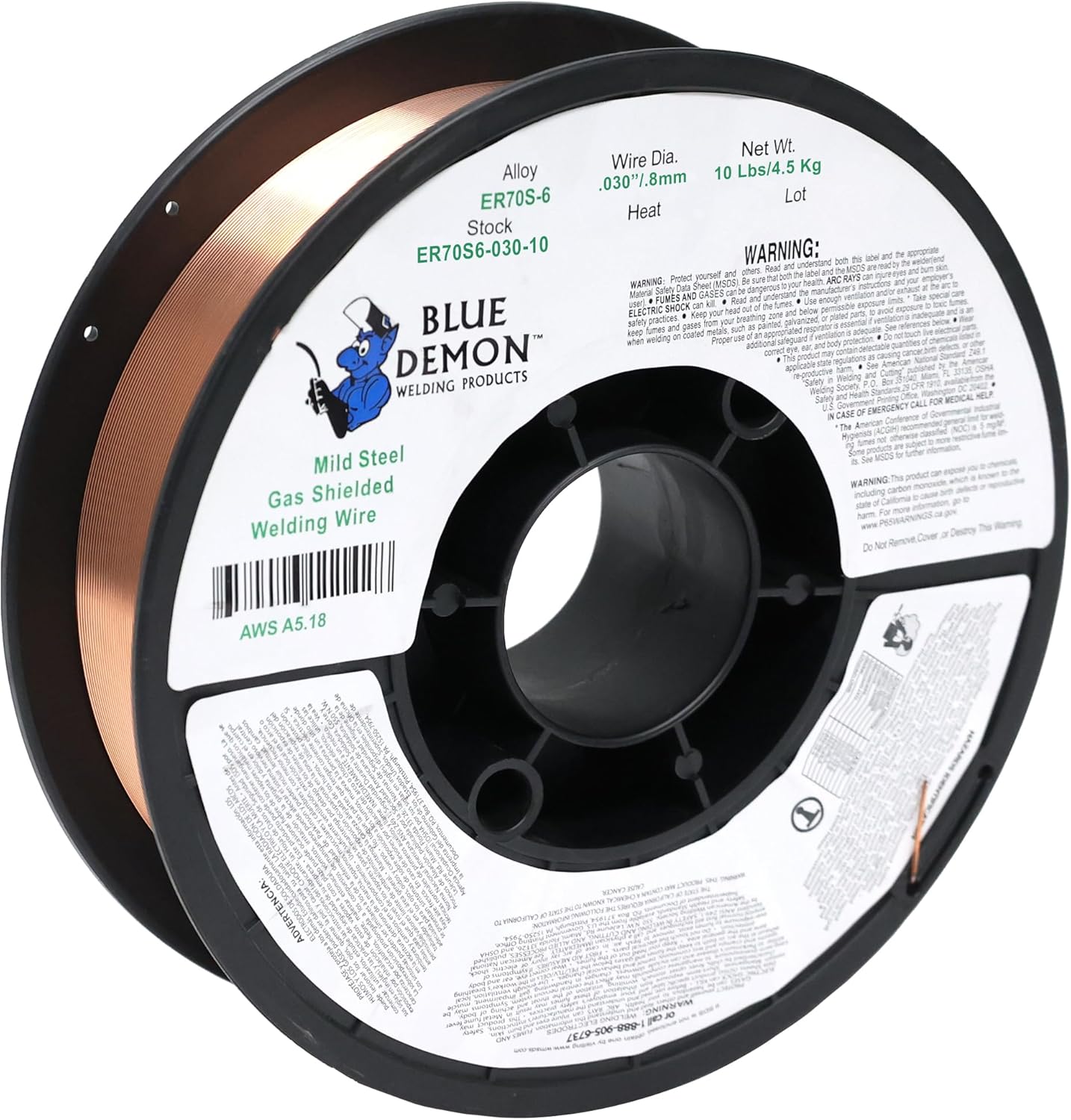
.030″ wire (0.8 mm) – light sheet & thin plate
Best for: 18–22 ga through about 1/8″ single-pass; auto repair, light fab.
Typical: 40–145 A; 120V or 240V to ~180 A; 75/25 preferred.
Traits: low heat, smooth arc, good vertical/overhead, feeds well on 10–15 ft guns.
Sweet spot: 20 ga–1/8″; can reach 3/16″ in multiple passes.
.035″ wire (0.9 mm) – “general purpose”
Best for: 16 ga (~0.060″) through about 1/4″; frames, brackets, most fab.
Typical: 50–180 A; 240V class machines; 75/25 or 90/10 for cleaner arc.
Traits: widest single-wire thickness window; all common alloys; good value.
Limits: usually too hot under 18 ga without care; slower than .045″ on heavy plate.
.045″ wire (1.2 mm) – structural & plate
Best for: 3/16″–1/2″; trailers, heavy frames, production flat/horiz.
Typical: 75–250 A; 180–250+ A class machines; 75/25 or 90/10.
Traits: high deposition, deep penetration, tolerates light rust better than small wire.
When over .035″: routine 1/4″+, production speed, enough machine headroom.
Limits: practical floor near 1/8″; bigger puddle for out-of-position work.
.052″ wire (1.4 mm) – heavy industrial
Best for: 3/8″–1″+ plate, shipbuilding, SAW-style workflows.
Typical: 100–300+ A on industrial three-phase gear.
Note: most shops never need it—equipment and volume must justify the spool.
Wire Size by Material Thickness
Thickness is the primary selector for wire diameter.
Complete material thickness chart
Material thickness
Gauge (sheet)
Best wire
Alternative
0.024″–0.030″
24–22 ga
.023″
.030″ (light touch)
0.030″–0.048″
22–20 ga
.030″
—
0.048″–0.060″
20–18 ga
.030″
.035″ (careful)
0.060″–0.075″
18–16 ga
.030″ or .035″
Either works
0.075″–0.105″
16–14 ga
.035″
.030″ (slow travel)
1/8″ (0.125″)
11 ga
.035″
.045″ (high heat)
3/16″ (0.1875″)
—
.035″ or .045″
Either works
1/4″ (0.25″)
—
.045″
.035″ (multi-pass)
5/16″ (0.3125″)
—
.045″
—
3/8″ (0.375″)
—
.045″ or .052″
.035″ (many passes)
1/2″ and up
—
.052″
.045″ (production)
Single-pass vs. multi-pass
Thicker plate with smaller wire means more passes. Example on 1/4″ steel: .045″ near 180–200 A often single-pass; .035″ at 140–160 A may need 2–3 passes; .030″ at 120–130 A may need 3–4+.
Thin-material overlap (16–18 ga)
Both .030″ and .035″ can work. Choose .030″ for uneven thickness, gaps, or vertical; .035″ for tight fit-up and flat/horizontal speed.
Wire Size by Amperage Range
Outside each wire’s band, the arc gets unstable or the wire burns back.
Wire
Min A
Optimal
Max A
.023″
30
40–75
90
.030″
40
60–120
145
.035″
50
80–160
180
.045″
75
120–220
250
.052″
100
150–280
300+
Matching wire to welder output
120V (about 80–140 A): favor .023″–.030″; .035″ only on thin stock; skip .045″.
240V light (140–180 A): .030″–.035″ sweet spot; .045″ only if you accept lower end of its range (≈3/16″ comfort).
240V pro (200–250 A): .035″ and .045″ cover most fab; optional .030″ for sheet.
Use the MIG Welding Calculator for starting volts, IPM, and gas flow once wire is chosen.
Solid Wire vs. Flux-Core Sizing
Flux-core is tubular—less metal cross-section than solid at the same labeled diameter—so it often runs one size larger than solid for the same job. See our solid vs flux-core comparison for process tradeoffs.
Thickness
Solid
Flux-core
18–20 ga
.030″
.030″ or .035″
16 ga
.030″ or .035″
.035″
14 ga–1/8″
.035″
.035″ or .045″
3/16″–1/4″
.035″ or .045″
.045″
5/16″–3/8″
.045″
.045″ or .052″
Self-shielded flux-core runs hotter and spatterier—generally avoid ultra-thin sheet. Gas-shielded flux-core is cleaner and common in .035″ / .045″ / .052″.
Contact Tip Selection
Tips must match wire size exactly (.030″ wire → .030″ tip). Oversized tips rattle and wander; undersized tips jam.
Wire
Typical tip life (rule of thumb)
Cost ballpark
.023″
10–20 lb wire
$3–5 ea
.030″
20–35 lb
$2–4 ea
.035″
35–50 lb
$1.50–3 ea
.045″
50–75 lb
$1.50–3 ea
Replace when the bore goes oval, arc gets erratic, or burn-back increases. Buy 10-packs so you always have the right bore.
Tip materials (quick)
Standard copper tips are cheap and fine for most work. Heavy-wall copper lasts longer on hot jobs. Chrome–zirconium tips cost more but can survive high-duty cycles—choose when tips are becoming a line-item on production lines.
Matching Wire Size to Welder Capacity
Your machine ceiling caps usable wire. On 120V, plan around .030″ as the “do everything reasonable” choice; on 240V 200A+ class, pairing .035″ + .045″ covers most structural ranges without fighting the feeder.
As an Amazon Associate, TestTalkHQ earns from qualifying purchases.
Aluminum Wire Sizing (Different Rules)
Aluminum conducts heat away faster—plan roughly 20–30% more current than steel for similar thickness. Feeding is the other battle: soft wire kinks in long liners, so spool guns and push-pull systems dominate.
Common wires: 4043 general (3003, 6061, 6063); 5356 higher strength / marine alloys (5052, 5083, 5086, 6061). Size the wire to thickness first, then verify alloy requirements on the WPS.
5 Common Wire Size Mistakes
1. “.035″ is universal”
It’s general-purpose for roughly 14 ga–1/4″. Outside that, you fight burn-through or crawl with multi-pass heat.
2. Wrong contact tip bore
“Close enough” tips cause wander, stubbing, and porosity. Match bore to wire.
3. Running wire outside its amp band
Big wire at low amps sputters; small wire at high amps burns back. Fix the diameter, not just the knob.
4. Using steel rules for aluminum
More amps, different feeding, and usually argon—revisit the aluminum table above.
5. Never changing spools
Yesterday’s .035″ on today’s 20 ga is a hole punch. Change wire when thickness class jumps.
When to Switch Wire Sizes
Worth a spool change: thickness changes ~50%+, batches of similar parts, quality-critical work, chronic burn-back/spatter from being outside the band.
Maybe skip: one quick repair, thickness still inside the wire’s happy range, time beats perfection.
Typical change sequence: run out or save partial spool → install spool → change tip to match → set drive tension → feed, trim, tune volts/wire speed on scrap (5–10 minutes).
Frequently Asked Questions
What is the most common MIG wire size?
.035″ is the default in many fab shops because it spans 14 ga–1/4″ well. Auto-focused shops often lean .030″; heavy structural shops lean .045″. Stock for what you weld most.
Can I use .030″ instead of .035″?
Yes—often better under ~1/8″. Tradeoff: lower deposition on thicker sections (more passes). The wire gauge calculator helps sanity-check.
What wire for 1/8″ steel?
.035″ at about 110–160 A is the usual first choice; .030″ near 120–140 A if you need a smaller puddle out-of-position; .045″ is usually unnecessary unless you are pushing speed with enough machine.
Does wire diameter affect amperage?
Yes—each diameter has a stable melt rate band. Wire speed sets delivered amps in short-circuit MIG; diameter shifts the whole curve.
What contact tip do I need?
Match the tip designation to the wire—no oversize “for slag” on solid MIG.
Thick steel with thin wire?
Possible with multiple passes and discipline; slower than correct-diameter wire and easier to overheat the wire itself if you chase amps.
Is .035″ really “general purpose”?
For the mid-thickness fab band, yes. It is not a free pass on 24 ga or 1/2″ plate without process changes.
Flux-core wire size?
Often step up one size versus solid for similar thickness; self-shielded runs hot—avoid ultra-thin sheet.
Penetration vs wire size?
At the same current, larger wire can change arc energy distribution and puddle volume—still need enough total heat for joint mass.
Stock multiple sizes?
If you bounce between thin sheet and 3/16″+ regularly, a .030″ + .035″ or .035″ + .045″ pair saves more time than fighting one spool.
Conclusion: choose wire by thickness and machine headroom
Match diameter to the material you actually weld, keep tips and drive rolls aligned with that diameter, and respect each wire’s amp band. Use the quick chart at the top for mild steel starting points, then refine with the MIG Welding Calculator, IPM guide, and scrap coupons—not guesses in the joint.