MIG Welding Settings Chart: Wire Speed & Voltage Guide
Stop guessing your MIG settings. Here’s exactly how to dial in wire speed, voltage, and gas flow for clean welds on any material thickness—plus a free calculator that does the math for you in seconds.
The Problem With Guessing MIG Settings
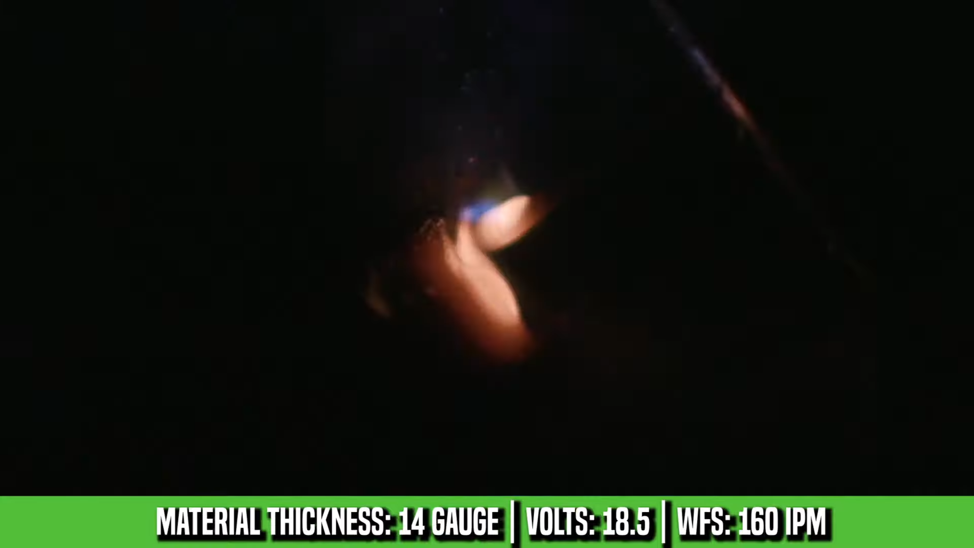
You know the drill. You’re standing in front of your welder with a piece of 1/8″ steel, and you’re trying to remember: was it 18 volts or 20? Wire speed at 280 IPM or 320? And what about the gas—15 CFH or 20?
So you take a guess, run a bead, and it looks like garbage. Too cold and you get a rope of BB’s sitting on top. Too hot and you burn through. Spatter everywhere. Now you’re wasting material trying to dial it in, and that’s assuming you even figure it out before you give up and move on.
I’ve been there. Ten years of metal fabrication, and I still see experienced welders struggling with this. The charts on the inside of your welder door help, but they’re generic. They don’t account for your specific material, your wire diameter, your shielding gas, or whether you’re welding flat, vertical, or overhead.
That’s why I built the MIG Welding Calculator. No more guessing. No more wasted material. Just plug in your specs and get the exact settings you need.
Why MIG Settings Actually Matter
Here’s what most people don’t understand: MIG welding is all about heat balance. Too much heat and you burn through. Too little and you don’t get penetration. The “right” setting is the narrow window where you get full fusion without destroying your base material.
Three things control your heat input:
- Wire Feed Speed (IPM) – How fast wire feeds through your gun. This is your primary amperage control on a MIG welder.
- Voltage – Controls your arc characteristics and how wide your bead spreads.
- Gas Flow Rate (CFH) – Protects your weld pool from contamination.
Get any one of these wrong and your weld suffers. Too much voltage with low wire speed? You get a flat, wide bead with poor penetration and excessive spatter. High wire speed with low voltage? The wire stubs into the puddle and you get a narrow, convex bead that might not fuse properly.
And that’s just for mild steel. Switch to stainless or aluminum and the whole game changes.
Master MIG Settings Chart: Mild Steel Reference
Here’s your quick reference chart for mild steel using 0.035″ wire and C25 gas (75% argon, 25% CO2). These are baseline settings for flat position welding.
| Material Thickness | Wire Speed (IPM) | Voltage | Gas Flow (CFH) |
|---|---|---|---|
| 16 gauge (0.060″) | 180-220 | 16-17 | 18-20 |
| 14 gauge (0.075″) | 200-240 | 16-18 | 18-20 |
| 1/8″ (0.125″) | 280-320 | 18-20 | 18-22 |
| 3/16″ (0.1875″) | 340-380 | 20-22 | 20-24 |
| 1/4″ (0.250″) | 380-420 | 22-24 | 20-24 |
| 3/8″ (0.375″) | 420-480 | 24-26 | 22-26 |
| 1/2″ (0.500″) | 480-550 | 26-28 | 24-28 |
Need settings for different wire sizes, materials, or positions? Use the MIG Welding Calculator for precise recommendations based on your exact setup.
The Rule of Thumb (And Why It’s Not Enough)
Most welders learn the basic rule: 1 amp per 0.001″ of material thickness for steel. So 1/8″ steel (0.125″) needs roughly 125 amps.
That’s a starting point. But it assumes you’re using 0.035″ wire, welding in flat position, using C25 gas, working with clean material, maintaining proper stick-out, and traveling at a reasonable speed.
Change any of those variables and the rule falls apart.
Welding 1/8″ steel in vertical? You need to drop your settings 15-20% or the puddle sags. Switching to stainless? You need about 10-15% less heat than mild steel. Using pure argon on aluminum? You need 25-30% MORE heat because aluminum conducts heat away so fast.
This is where most people get lost. The calculator handles all of these adjustments automatically.
How to Use the MIG Welding Calculator
I designed this tool for speed. You shouldn’t have to read a manual to figure out welding settings.
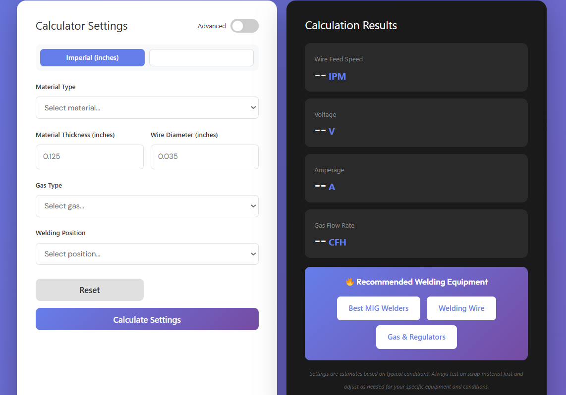
Step 1: Select Your Material Type
Choose from mild steel (most forgiving), stainless steel (needs lower settings, conducts heat poorly), or aluminum (requires higher settings and pure argon gas). The calculator adjusts all recommendations based on this selection.
Step 2: Enter Material Thickness
Type in your actual material thickness in inches. Be accurate here—the difference between 0.125″ and 0.1875″ is significant in terms of heat input needed.
If you’re welding two different thicknesses together (say, 1/8″ to 1/4″), use the thinner material’s thickness and increase your settings slightly. The thin material is what will burn through first.
Step 3: Select Wire Diameter
Common sizes: 0.023″ for super thin material, 0.030″ for general purpose work, 0.035″ as the industry standard, and 0.045″ for thicker material and heavy fabrication.
The wire diameter dramatically affects your settings. Thicker wire requires higher voltage and slower wire speed to maintain the same heat input. The MIG calculator accounts for this automatically.
Step 4: Choose Your Shielding Gas
Your options: C25 (75% Ar / 25% CO2) is the industry standard for mild steel. Pure CO2 gives deep penetration with more spatter. Pure Argon is required for aluminum. Tri-Mix is premium gas for stainless steel.
Gas selection affects both your arc characteristics and your required flow rate. The calculator adjusts for this.
Step 5: Select Welding Position
Position matters more than most people realize. Flat (1G) allows maximum heat input and fastest travel speed. Horizontal (2G) needs 5% reduction from flat. Vertical-Up (3G-Up) requires 15% reduction. Vertical-Down (3G-Down) needs 25% reduction and only works on thin material. Overhead (4G) needs 20% reduction from flat.
Why? Gravity. In flat position, gravity helps hold your puddle. In vertical or overhead, you need less heat or the puddle sags and runs.
Step 6: Get Your Results
The calculator instantly gives you wire feed speed range, voltage range, and gas flow rate. Start in the middle of each range and adjust based on what you see in the puddle.
Position-Specific Settings Adjustments
Here’s how to modify your flat position settings for other positions. These percentages apply to both wire speed and voltage.
| Position | Adjustment from Flat | Travel Technique | Common Issues |
|---|---|---|---|
| Flat (1G) | Baseline (100%) | Straight stringer or slight weave | Undercut if too fast, excessive buildup if too slow |
| Horizontal (2G) | Reduce 5% | Slight upward angle to fight sag | Bottom edge undercut, top edge cold lap |
| Vertical-Up (3G) | Reduce 15% | Tight side-to-side weave or triangles | Puddle sag, undercut on edges |
| Vertical-Down (3G) | Reduce 25% | Fast travel, thin material only | Poor penetration, cold lap |
| Overhead (4G) | Reduce 20% | Small circles or tight weave, fast travel | Puddle drops, excessive spatter |
Example: If your flat settings are 300 IPM at 19V, vertical-up would be approximately 255 IPM at 16V. Always start conservative and work your way up.
Material-Specific Settings Guide
Mild Steel (Carbon Steel)
Mild steel is the most forgiving material for MIG welding. It has good thermal conductivity, consistent melting characteristics, and works well with C25 or pure CO2 shielding gas.
Best Gas: C25 (75% argon, 25% CO2) for smooth arc and low spatter. Pure CO2 if you want deeper penetration and don’t mind more cleanup.
Wire Type: ER70S-6 is your standard choice. The silicon content helps the weld wet out smoothly.
Common Mistake: Not cleaning mill scale, rust, or paint before welding. Even though MIG can burn through some contamination, you’ll get better results with clean metal.
Stainless Steel (304, 316)
Stainless conducts heat poorly compared to mild steel, which means it holds heat longer. You need to reduce your settings by 10-15% compared to mild steel of the same thickness.
Best Gas: Tri-mix (90% helium, 7.5% argon, 2.5% CO2) for production work. Pure argon works but gives a ropier bead. C25 will work in a pinch but you’ll get more spatter.
Wire Type: Match your filler metal to your base metal. ER308L for 304 stainless, ER316L for 316 stainless. Use 309L when welding stainless to mild steel.
Common Mistake: Using the same settings as mild steel. You’ll overheat the material, get excessive warpage, and potentially sensitize the stainless (causing corrosion issues later).
Settings Adjustment: For 1/8″ stainless, if mild steel calls for 300 IPM at 19V, drop to 255-270 IPM at 16-17V.
Aluminum (5052, 6061)
Aluminum is tricky. It conducts heat extremely well, which means it sucks heat away from your puddle fast. You need 25-30% MORE heat than mild steel of the same thickness, and you absolutely must use pure argon.
Best Gas: Pure argon only. No exceptions. C25 or CO2 will oxidize aluminum instantly and ruin your weld.
Wire Type: ER4043 for general purpose (contains silicon, better for castings). ER5356 for structural work (higher strength, better for 5xxx and 6xxx series aluminum).
Common Mistake: Not removing the oxide layer before welding. Aluminum forms an oxide coating that melts at 3,700°F while the base aluminum melts at 1,200°F. Wire brush with a stainless steel brush (not one you’ve used on steel) right before welding.
Settings Adjustment: For 1/8″ aluminum, if mild steel calls for 300 IPM at 19V, bump to 375-390 IPM at 22-24V. Use a push technique (torch angle away from the puddle) to prevent porosity.
For precise settings on any material, use the MIG Welding Calculator and select your material type. It handles all the math automatically.
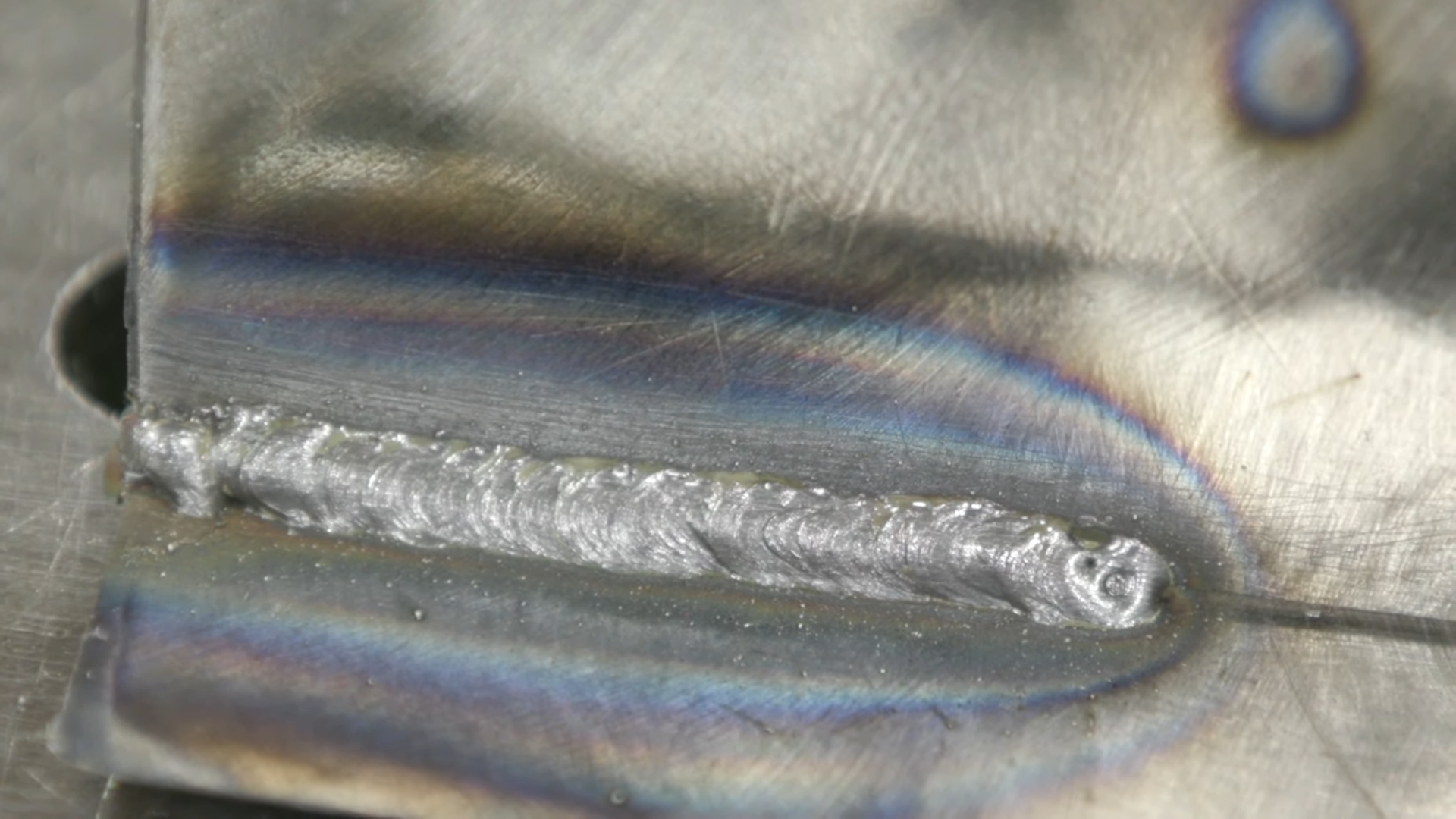
Troubleshooting Guide: What Your Weld Is Telling You
Your weld bead is giving you feedback. Here’s how to read it and fix problems.
Problem: Excessive Spatter
Symptoms: BBs of metal everywhere, cleanup takes longer than welding, spatter sticking to nozzle.
Causes:
- Voltage too high for your wire speed
- Wrong shielding gas (pure CO2 creates more spatter than C25)
- Contaminated base metal (oil, paint, rust)
- Wire stick-out too long
- Welding on dirty or galvanized steel
Fixes:
- Drop voltage by 1-2V and test
- Switch from CO2 to C25 gas if possible
- Clean your material with wire brush or grinder
- Reduce stick-out to 3/8″ to 1/2″
- Apply anti-spatter spray to nozzle and surrounding metal
Problem: Porosity (Holes in the Weld)
Symptoms: Small holes or voids visible on weld surface or in cross-section, weld looks like a sponge.
Causes:
- Gas flow too low (not enough shielding)
- Gas flow too high (creates turbulence, pulls in air)
- Contaminated gas line or empty cylinder
- Welding in windy conditions without protection
- Base metal contamination (moisture, oil, zinc coating)
- Dirty wire or contact tip
Fixes:
- Check gas flow rate (should be 18-22 CFH for most applications)
- Verify gas cylinder isn’t empty or contaminated
- Use welding screens or shields if working outdoors
- Clean base metal thoroughly before welding
- Replace worn liner, contact tip, or nozzle
- On aluminum, use push technique and ensure oxide layer is removed
Problem: Undercut (Groove Along Weld Edges)
Symptoms: Depression or groove along one or both edges of weld bead, looks like the base metal was carved away.
Causes:
- Travel speed too fast
- Voltage too high
- Arc too long
- Wrong torch angle
Fixes:
- Slow down your travel speed
- Reduce voltage by 1-2V
- Keep tighter arc length (wire closer to puddle)
- Adjust torch angle—should be 10-15° push angle in flat position
- Use slight side-to-side weave to fill edges properly
Problem: Cold Lap (Poor Fusion at Edges)
Symptoms: Weld bead sits on top of base metal without fusing into it, visible line where weld meets base metal.
Causes:
- Travel speed too fast
- Not enough heat (wire speed too low or voltage too low)
- Wrong torch angle pushing puddle away from edges
- Base metal too cold
Fixes:
- Slow down travel speed
- Increase wire speed by 20-30 IPM
- Increase voltage by 1V
- Use slight side-to-side motion to ensure edge fusion
- Preheat material if welding in cold shop (below 50°F)
Problem: Burn-Through (Holes in Base Metal)
Symptoms: Holes melt through base metal, molten metal drips through backside.
Causes:
- Settings too hot for material thickness
- Travel speed too slow
- Gap too large in joint fit-up
- Poor joint design for material thickness
Fixes:
- Reduce wire speed by 30-50 IPM
- Reduce voltage by 2-3V
- Speed up travel significantly
- Use stitch welding (short beads with gaps) instead of continuous bead
- Add backing bar or use pulse welding if available
- Switch to smaller wire diameter (0.030″ instead of 0.035″)
Problem: Ropey or Convex Bead
Symptoms: Bead sits tall on material with rope-like appearance, looks like stacked pennies.
Causes:
- Voltage too low for wire speed
- Travel speed too fast
- Arc too short (wire too close to work)
Fixes:
- Increase voltage by 1-2V
- Slow down travel speed
- Increase stick-out slightly (1/2″ from contact tip)
- Watch your puddle—should spread and wet out, not pile up
Problem: Excessive Buildup or Sagging Puddle
Symptoms: Too much weld metal deposited, bead droops or sags especially in vertical or overhead.
Causes:
- Travel speed too slow
- Wire speed too high
- Voltage too high causing fluid puddle
- Wrong position settings (using flat settings in vertical)
Fixes:
- Speed up travel significantly
- Reduce wire speed by 30-50 IPM
- Reduce voltage by 2V
- For vertical/overhead, reduce both wire speed and voltage by 15-20%
- Use tighter weave pattern with faster movement
Wire Size Selection Chart
Choosing the right wire diameter makes a huge difference. Here’s when to use each size.
| Wire Diameter | Best For | Material Thickness Range | Pros | Cons |
|---|---|---|---|---|
| 0.023″ | Sheet metal, automotive bodywork | 24ga – 16ga | Very low heat input, minimal burn-through risk | Hard to find, limited to light material, lower deposition rate |
| 0.030″ | Sheet metal, light fabrication, automotive | 18ga – 1/8″ | Good for thin material, widely available, less burn-through | Slower on thick material, more wire changes |
| 0.035″ | All-around fabrication, structural steel | 16ga – 1/4″ | Industry standard, most versatile, good balance | Can burn through very thin material if not careful |
| 0.045″ | Thick material, heavy fabrication, production | 3/16″ – 1/2″+ | High deposition rate, fewer wire changes, deeper penetration | Requires more powerful welder, not suitable for thin material |
Most hobbyist and light fabrication welders run 0.030″ or 0.035″ wire. If you’re only buying one spool, get 0.035″—it’s the most versatile.
Gas Flow Rate: Finding the Sweet Spot
Gas flow is one of those things people either ignore completely or massively overthink. Here’s what actually matters.
Standard Flow Rate: 18-22 CFH for most applications. That’s cubic feet per hour, which you set on your regulator.
Too Low (under 15 CFH): You get porosity because there’s not enough shielding gas protecting your puddle. Atmospheric oxygen and nitrogen contaminate the weld.
Too High (over 25 CFH): You create turbulence that actually PULLS in atmospheric contamination. Plus you’re wasting expensive gas.
When to Adjust:
- Increase to 22-25 CFH if welding outdoors with light breeze, using a larger nozzle, or welding at very high amperages
- Decrease to 15-18 CFH if welding in confined space, using small nozzle, or if you’re seeing turbulence in the puddle
- Overhead welding: Increase by 2-3 CFH because gravity works against gas coverage
Use the CFM Calculator if you need to convert between flow rate units or calculate gas consumption for job costing.
Advanced Settings: Fine-Tuning Your Technique
Once you have your basic settings dialed in with the calculator, here are the technique factors that separate good welds from great welds.
Travel Speed
Too fast and you get a narrow, ropey bead with poor penetration. Too slow and you get excessive buildup and potential burn-through. Watch your puddle—if it’s getting too big, speed up. If it’s too small, slow down.
A good baseline is 8-12 inches per minute for most flat welding. Vertical-up is slower (4-8 IPM), overhead is faster (10-15 IPM).
Stick-Out Distance
Keep 3/8″ to 1/2″ of wire extending from your contact tip. Longer stick-out reduces your effective amperage because the wire preheats from resistance. Shorter stick-out can overheat your contact tip and cause wire feeding problems.
On aluminum, you want stick-out on the shorter side (3/8″) because aluminum wire is softer and can bird-nest more easily with excessive stick-out.
Travel Angle
For flat and horizontal, use a 10-15° push angle (drag technique). Push angle gives you better visibility, less spatter, and better gas coverage. The exception is aluminum—always use push angle on aluminum to prevent porosity.
For vertical-up, use a slight drag or perpendicular angle. For overhead, perpendicular or slight push works best.
Torch Position and Work Angle
Keep your torch perpendicular to the work in terms of side-to-side. Tilting left or right causes uneven heat distribution and can create undercut on one side.
For fillet welds (T-joints or lap joints), split the angle equally. On a 90° corner, hold your torch at 45° to both pieces.
When to Adjust Settings Beyond the Calculator
The calculator gives you a starting point based on ideal conditions. Here’s when you’d adjust from there.
Increase Settings If:
- Your material is dirty, rusty, or painted (needs more heat to burn through contamination)
- You’re traveling faster than normal (need more heat to compensate)
- You’re doing root passes on thick material (need extra penetration)
- Your material is cold (winter welding in unheated shop below 50°F)
- You’re welding cast iron or other high-carbon materials
Decrease Settings If:
- You’re working with very thin material (16ga or thinner)
- You’re tack welding (short stitch beads, not continuous)
- You’re worried about warpage (heat-sensitive applications)
- You’re welding a corner joint where heat sinks into both pieces
- You’re doing cover passes where penetration isn’t critical
These are judgment calls based on your specific situation. But starting from the calculator’s recommendations means you’re already in the ballpark instead of completely guessing.
Common MIG Welding Mistakes (That the Calculator Prevents)
Mistake #1: Using Stick Welding Settings for MIG
Stick welding and MIG are completely different processes. That 1 amp per 0.001″ rule from stick doesn’t directly translate because wire feed speed—not a dial—controls your amperage in MIG. The calculator converts material thickness into actual wire speed recommendations.
Mistake #2: Ignoring Position Adjustments
Someone dials in perfect flat settings, then tries to weld vertical with the same numbers. The puddle runs, they get undercut, and they blame the welder. The calculator automatically adjusts for position—if you’re going vertical, it drops your recommended settings 15% automatically.
Mistake #3: Wrong Gas Flow Rate
“More gas is better, right?” Wrong. Excessive gas flow creates turbulence that actually pulls in atmospheric contamination. You end up with porosity despite flowing way too much expensive gas. The calculator gives you the optimal flow rate for your specific setup.
Mistake #4: Not Accounting for Material Type
Stainless and aluminum don’t weld like mild steel. Stainless conducts heat poorly, so it holds heat and needs lower settings. Aluminum conducts heat excellently, so it sucks heat away and needs higher settings plus pure argon. The calculator handles these material-specific adjustments automatically.
Mistake #5: Wrong Wire Size for the Job
Using 0.045″ wire on sheet metal is asking for burn-through. Using 0.030″ wire on 3/8″ plate means you’ll be there all day. Match your wire size to your material thickness range and let the calculator adjust settings accordingly.
How Different Welders Vary
Every welder is a little different. A Lincoln MIG might read slightly different voltage numbers than a Miller or Hobart. This is why the calculator gives you ranges instead of single numbers.
Start in the middle of the recommended range, run a test bead, and adjust. Once you know how your specific machine behaves, you’ll start hitting the sweet spot faster.
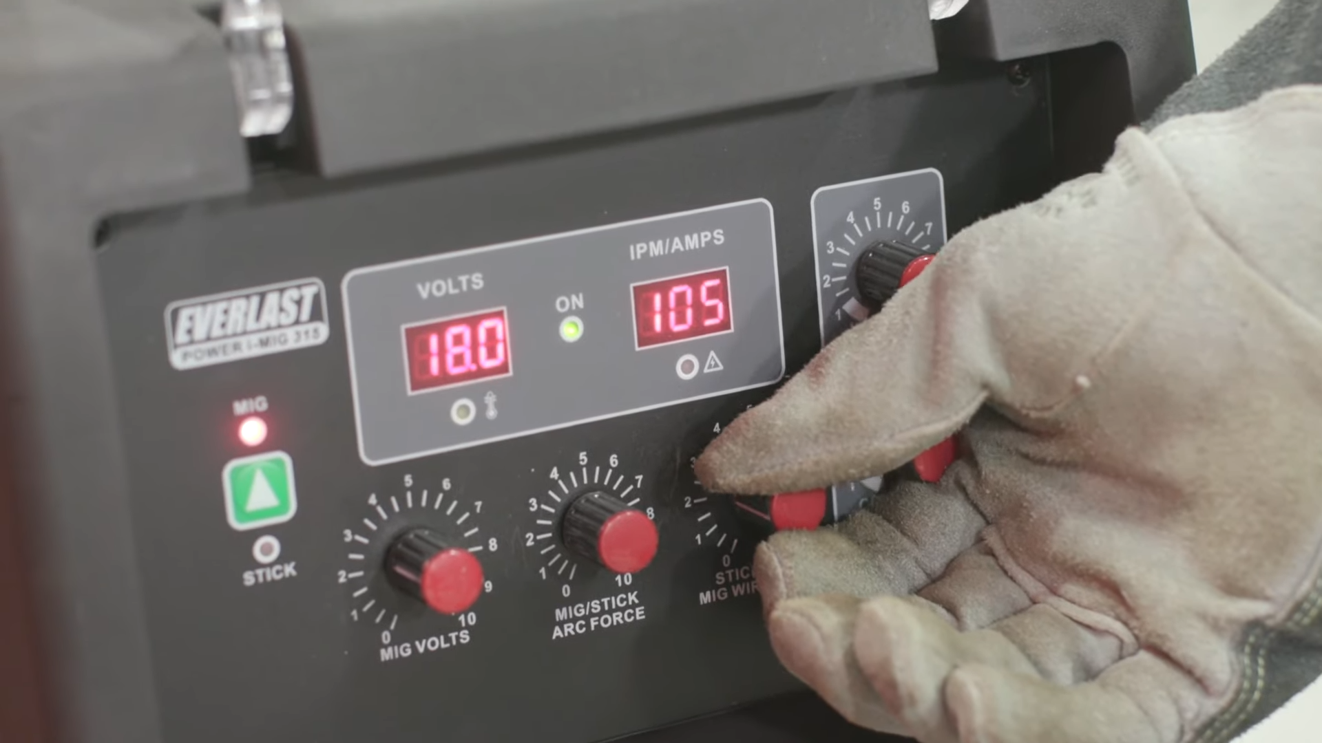
If your welder has a voltage dial that goes 1-10 instead of showing actual voltage numbers, you’ll need to correlate the calculator’s voltage recommendation to your dial settings. Most 120V welders max out around 20V, so if the calculator says 19V, you’re probably around 7-8 on a 1-10 dial.
For more help with calculating other welding parameters, check out the Heat Input Calculator to ensure you’re staying within procedure specifications.
Real-World Application: Step-by-Step Setup
Let’s walk through a complete setup for a common job: welding 1/8″ mild steel plate in flat position.
Step 1: Measure material thickness accurately. It’s 0.125″ (1/8″).
Step 2: Check what’s in your welder. You have 0.035″ ER70S-6 wire and C25 gas.
Step 3: Go to the MIG Welding Calculator and enter: Mild steel, 0.125″ thickness, 0.035″ wire, C25 gas, flat position.
Step 4: Calculator recommends wire speed 280-320 IPM (start at 300), voltage 18-20V (start at 19), gas flow 18-22 CFH (set at 20).
Step 5: Set your welder to these specs. Set gas flow with regulator while triggering gun.
Step 6: Run a 3-4″ test bead on scrap material same thickness as your job.
Step 7: Evaluate the bead. Too hot? Drop to 280 IPM and 18V. Too cold? Increase to 320 IPM and 20V. Just right? Write down these settings.
Step 8: Weld your actual joint using the dialed-in settings.
This whole process takes 2-3 minutes instead of 15-20 minutes of trial and error.
Why I Built This Calculator
I got tired of watching fabricators—good fabricators—struggle with something that should be simple. MIG welding isn’t rocket science, but the setup process is unnecessarily complicated when you’re trying to remember formulas and adjust for different variables.
I wanted a tool that takes 30 seconds to use, accounts for all the variables (material, thickness, wire, gas, position), gives you professional-grade settings every time, and doesn’t require you to be a welding engineer to use.
That’s what this calculator does. It’s free, it’s fast, and it works.
Additional Resources and Related Tools
For comprehensive welding resources, visit the Welding Calculators and Tools hub page for access to all available calculators and guides.
Related calculators that complement MIG settings:
- TIG Welding Calculator – Amperage, tungsten size, and gas flow for TIG welding
- Stick Welding Calculator – Rod size and amperage for SMAW processes
- Stick Welding Rod Chart – Complete electrode selection guide
- Heat Input Calculator – Calculate and verify welding heat input for code work
- Metal Weight Calculator – Calculate material weight for estimation and shipping
The Bottom Line
Stop wasting time and material guessing your MIG settings. Use the MIG Welding Calculator, get accurate recommendations in 30 seconds, and start welding instead of troubleshooting.
Whether you’re welding 1/16″ sheet metal or 1/2″ plate, mild steel or aluminum, flat or overhead—the calculator handles it. Get your settings right the first time, every time.
Disclaimer: Always follow manufacturer recommendations, welding procedures, and safety protocols. This guide is for educational purposes. For critical applications, consult qualified welding engineers and follow applicable codes. See our full disclaimer.
Go deeper than the chart: The MIG Welding Settings Guide explains how the MIG Welding Calculator builds voltage, wire speed, and gas flow from these baselines — plus puddle judgment, transfer mode, and troubleshooting.

MIG Settings Chart
Both sizes - 8.5x11 and the 18x24 shop poster. $5.99.