Wire feed speed sets amperage in short-circuit MIG—and amperage sets penetration. Start from IPM (material thickness in thousandths × burn-off factor), then tune voltage for arc sound. This page is the chart + the method; the calculators turn it into numbers for your machine. If you’ve ever stood in front of a MIG welder with the wire feed speed dial in one hand and a piece of scrap metal in the other, wondering where to start, you’re not alone. Most welders are taught to “dial it in by sound”—adjust wire speed and voltage until you hear that bacon-frying sizzle. That works if you’ve got unlimited scrap metal and time to burn through practice runs. But what if you could calculate the exact wire feed speed you need before striking an arc? Wire feed speed directly controls amperage in MIG welding, which means it determines penetration depth, heat input, and whether you blow through thin material or fail to fuse thick plate. Set it too low and you get cold welds with poor penetration. Set it too high and you burn through, create excessive spatter, and waste wire. The difference between a good weld and a failed joint often comes down to 50-100 inches per minute of wire speed. This guide gives you the complete wire feed speed chart for MIG welding, explains the calculation formula that works for any material thickness, and shows you exactly how wire diameter (.023″, .030″, .035″, .045″) affects the settings you need. You’ll learn how to set wire speed first based on material thickness, then adjust voltage by ear—a method that gets you dialed in fast no matter what machine you’re running. Use our free MIG Welding Calculator to get instant wire feed speed and voltage recommendations for your specific material and wire size. Short-circuit MIG, .030″ ER70S-6 mild steel, typical 75/25 or CO2. IPM from the same burn-off factors as the full charts below—then set volts by arc. Verify IPM with the 6-second test; dials and readouts drift. For other wire diameters, use the and full charts below, then sanity-check with the MIG Welding Calculator and wire size guide. Need the numbers, not the lecture? Use the calculators below when you want wire speed, voltage, gas flow, or wire usage without guessing. Wire feed speed is how fast electrode wire feeds through your MIG gun, measured in inches per minute (IPM). When you increase wire feed speed, you’re pushing more wire into the arc per minute, which requires more current (amperage) to melt that wire. When you decrease wire feed speed, less wire enters the arc, requiring less current. Here’s the critical relationship: Wire feed speed controls amperage. Amperage controls penetration. This is why wire feed speed is the FIRST setting you adjust when dialing in a MIG welder. It determines how much heat you’re putting into the weld, how deep you penetrate the base metal, and how much filler metal you’re depositing. Voltage (which we’ll cover later) primarily affects bead width and arc characteristics, but wire speed is what gets you in the ballpark for proper penetration. MIG welders measure wire feed speed in IPM rather than feet per minute or meters per minute because it’s easier to visualize and measure. If you trigger your gun for exactly 6 seconds and measure the wire that came out, you get inches in 6 seconds. Add a zero, and that’s your IPM. Example: Trigger gun for 6 seconds → 15 inches of wire came out → Wire feed speed is 150 IPM This method works because rulers don’t lie. Digital readouts on cheaper MIG welders can be off by 10-30%, but a tape measure is always accurate. This is the fastest way to verify your machine’s actual wire feed speed versus what the dial claims. More wire feeding into the arc = more amperage required to melt it. The relationship is nearly linear up to about 250 amps. This is why the “one amp per thousandth of material thickness” rule works so well for calculating wire feed speed. Example: Once you know the amperage you need, you can calculate the exact wire feed speed required to deliver that amperage—which is where the formula comes in. Here’s the formula that lets you calculate wire feed speed for any material thickness and wire diameter: Wire Feed Speed (IPM) = Material Thickness (thousandths) × Wire Burn-Off Factor Scenario: Welding 1/8″ steel plate with .030″ wire Step 1: Convert material thickness to thousandths Step 2: Find burn-off factor for .030″ wire Step 3: Calculate wire feed speed Result: Set your MIG welder to 250 inches per minute for 1/8″ steel with .030″ wire. Step 1: Convert thickness Step 2: Find factor for .035″ wire Step 3: Calculate The burn-off factor represents how much wire of that diameter can be melted per amp of current. Smaller wire (.023″) has a higher factor (3.5) because thin wire melts faster—you need more wire speed to achieve the same amperage as thicker wire. Larger wire (.045″) has a lower factor (1.2) because thick wire melts slower and carries more current per inch of wire. This formula is based on the “one amp per thousandth” rule, which holds true from about 50 amps up to 250 amps. Beyond 250 amps (welding 1/4″ plate and thicker), the relationship becomes less linear, but the formula still gets you close enough to dial in by sound from there. Here’s the complete reference chart showing recommended wire feed speeds for common material thicknesses across all four standard MIG wire diameters: Note: .023/.024″ wire is best for sheet metal and thin gauge work. It’s very forgiving on low voltage settings and less likely to blow through thin material. *Note: Beyond 1/4″, the one-amp-per-thousandth rule breaks down. Use 300 amps for 3/8″ material. Use .045″ wire for: Heavy structural steel, thick plate fabrication, and applications requiring deep penetration and high deposition rates. One page. MIG, TIG, stick and flux core settings by thickness. $3.99 19 pages. Four processes, stainless and aluminum, symbols and inspection. $12.99 Price the job, then hand over a quote with no internal numbers. Excel or Google Sheets. Best on a computer. $29.00 Card, 19-page guide and the estimator workbook. All six files. Excel or Google Sheets. Best on a computer. $34.99 $45.98 if bought separately — save $10.99 Checkout opens in a new tab. Consumables that keep feeding honest—liners, tips, gas, and wire that match what the charts assume As an Amazon Associate, TestTalkHQ earns from qualifying purchases. Wire diameter dramatically changes the wire feed speed you need for the same material thickness. Understanding why helps you choose the right wire for your application and troubleshoot problems. Burn-off factor: 3.5 Characteristics: Best for: Automotive body panels, HVAC ductwork, thin gauge fabrication, anything under 1/8″ thick. Drawback: Thin wire kinks easily. You MUST reduce drive roll tension to allow slight slippage, or you’ll get constant bird-nests when the wire welds to the contact tip. Burn-off factor: 2.0 Characteristics: Best for: General fabrication, if you only want to keep one wire size on hand, this is it. Handles 80% of shop welding tasks. Why it’s popular: .030″ wire strikes the perfect balance—thick enough to resist bird-nesting, thin enough not to overpower sheet metal, and available everywhere. Burn-off factor: 1.6 Characteristics: Best for: Structural steel, 3/16″ to 3/8″ plate, agricultural equipment repair, trailer fabrication. Trade-off: Too much heat for thin material. You’ll blow through 18 gauge sheet with .035″ wire before you can blink. Burn-off factor: 1.2 Characteristics: Best for: 1/4″ plate and thicker, heavy equipment repair, earth-moving equipment, mining machinery. When to use it: When you need to weld 3/8″ to 1/2″ plate and want maximum penetration with fewer passes. .045″ wire deposits metal FAST. Wire feed speed and voltage are NOT independent—they work together to create a stable arc. Set one wrong and the other becomes nearly impossible to dial in. Here’s how they interact: Wire speed controls: Wire speed does NOT control: Voltage controls: Voltage does NOT control: Imagine you set wire feed speed to 250 IPM (correct for 1/8″ steel with .030″ wire). Here’s what happens at different voltages: Voltage too low (15-16V): Voltage just right (18-19V): Voltage too high (22-24V): Here’s what happens when you change wire feed speed by 100 IPM while holding voltage constant: Baseline: 271 IPM at 19V on 3/16″ material (recommended setting) Reduced to 171 IPM (100 IPM lower): Increased to 371 IPM (100 IPM higher): This is why you set wire speed FIRST (based on material thickness), THEN adjust voltage to get a stable arc. This method gets you dialed in fast, even on an unfamiliar machine with worn-off dial markings. Here’s the step-by-step process: Use the formula: Wire Speed = Material Thickness (thousandths) × Burn-Off Factor Example: 1/8″ steel (.125″) with .030″ wire Most MIG welders max out around 700-800 IPM. Use this to your advantage: If your machine’s wire speed maxes at 700 IPM: For 250 IPM on a 700 IPM max machine, set the dial to approximately 35-40%. Don’t trust the dial—verify actual wire speed: Example: 15 inches came out in 6 seconds = 150 IPM actual wire speed If you wanted 250 IPM but only got 150 IPM, turn the dial up and test again. Digital readouts can be off by 20-30%, but rulers don’t lie. Set voltage to the LOWEST setting on your machine. This ensures you won’t burn through on your first test weld. Make a short test weld (2-3 seconds). You’ll hear one of three things: Popping, stuttering, wire stubbing: Voltage too low. Increase one notch. Smooth bacon-frying sizzle: Perfect! You’re done. Loud crackling, excessive spatter: Voltage too high. Decrease one notch. Keep adjusting voltage one notch at a time until you hear that smooth sizzle. Wire speed stays locked in—you’re ONLY adjusting voltage. Settings calculated above work for flat and horizontal welding. For vertical or overhead: Example: Welding 1/4″ vertical? Use settings for 3/16″ or 1/8″ material instead. Here are complete settings (wire speed AND voltage) for common material thicknesses using .030″ wire: Wire speed: 96 IPM Common mistake: Going too slow causes burn-through. Move fast! Wire speed: 120 IPM Wire speed: 150 IPM Wire speed: 250 IPM This is the “sweet spot” for .030″ wire—everything just works. Wire speed: 376 IPM (round to 380) Wire speed: 500 IPM Note: 1/4″ is near the upper limit for .030″ wire. Consider switching to .035″ or .045″ for better results. Causes: Fix: Prevention: Never touch the contact tip to the workpiece when starting. Arc should start in free air, then move to the joint. Causes: Fix: Cause: Digital readouts and dials on cheaper machines are often inaccurate. Fix: Use the 6-second test to verify actual wire speed. Adjust dial until 6-second test gives the IPM you calculated. Ignore what the dial says—trust the measurement. Causes: Fix: Cause: Flat welding settings are too hot for vertical. Fix: Reduce wire speed by selecting settings for 1-2 thickness steps LOWER than actual material. Example: Welding 1/4″ vertical? Use settings for 1/8″ or 3/16″ instead. Vertical welding needs less heat because gravity slows the puddle. This page already functions as the Chart deliverable: it contains wire-diameter burn-off factors, four diameter-specific IPM tables, thickness/voltage settings, and complete setup prose. For stubbing, bird-nesting, burn-back, feed-path restriction, spatter, and bad bead symptoms, use Common MIG Welding Problems and Solutions. For amperage symptoms across MIG, TIG, and Stick, use Welding Amperage Troubleshooting. For the calculator logic and set-WFS-first puddle technique, use the MIG Welding Settings Guide. Convert a known value directly with the Wire Feed Speed to Amps Calculator. For 1/8″ steel (125 thousandths thick), wire feed speed depends on wire diameter: .023″ wire needs 438 IPM, .030″ wire needs 250 IPM, .035″ wire needs 200 IPM, and .045″ wire needs 150 IPM. The most common choice is .030″ wire at 250 IPM, which delivers approximately 125 amps—perfect for 1/8″ material. Use the 6-second test: Hold the MIG trigger for exactly 6 seconds and measure how much wire came out with a tape measure or ruler. Take that measurement in inches and add a zero—that’s your wire feed speed in IPM. For example, if 15 inches of wire came out in 6 seconds, your wire speed is 150 IPM. This method is more accurate than most digital readouts. .030″ wire requires higher wire feed speed than .035″ wire for the same material thickness because thinner wire melts faster. For 1/8″ steel, .030″ wire needs 250 IPM while .035″ wire only needs 200 IPM. The burn-off factors are different: 2.0 for .030″ wire versus 1.6 for .035″ wire. Thicker wire carries more current per inch, so you need less speed to achieve the same amperage. Always set wire feed speed FIRST based on material thickness, then adjust voltage to get a stable arc. Wire speed controls amperage and penetration—the foundation of your weld. Voltage just fine-tunes arc characteristics and bead shape. If you set voltage first, you’re guessing blindly. Calculate the correct wire speed using the formula (thickness × burn-off factor), set it on the machine, then dial in voltage by sound until you hear a smooth bacon-frying sizzle. Bird-nesting with .023/.024″ wire happens because the wire is so thin it kinks easily when drive roll tension is too tight. If the wire welds to the contact tip or sticks to the workpiece, the drive rolls keep pushing but the wire can’t move forward—so it kinks and tangles behind the drive rolls. Fix this by reducing drive roll tension to allow slight slippage, checking for wire welded inside the contact tip, and never starting with the contact tip touching the workpiece. No, vertical welding requires lower wire feed speed (and lower heat) than flat welding on the same material thickness. Gravity pulls the molten puddle downward in vertical position, so too much heat causes the weld to sag and run. Reduce wire speed by selecting settings for material 1-2 thickness steps thinner than what you’re actually welding. For example, welding 1/4″ plate vertically, use settings for 3/16″ or 1/8″ material instead. Aluminum MIG welding requires higher wire feed speeds than steel because aluminum has higher thermal conductivity and melts at lower temperatures. For 1/8″ aluminum with .035″ ER4043 wire, you typically need 300-350 IPM (versus 200 IPM for steel). The exact setting also depends on whether you’re using spray transfer (higher speed) or short circuit transfer (lower speed). Aluminum is less forgiving than steel—use our calculator for precise recommendations. Wire feed speed directly controls penetration because higher wire speed = more amperage = more heat = deeper penetration. In penetration tests, reducing wire speed by 100 IPM produces noticeably shallower penetration, while increasing wire speed by 100 IPM creates significantly deeper penetration. This is why wire speed is set based on material thickness—you need enough penetration to fuse the joint properly without burn-through. Too-high wire feed speed delivers excessive amperage, causing burn-through on thin material, excessive spatter, a tall convex bead profile with too much reinforcement, and an unstable “poppy” arc that’s hard to control. You’ll also waste wire and shielding gas. If you’re burning through or seeing excessive buildup on top of the weld with poor tie-in to the base metal, reduce wire feed speed by 50-100 IPM and test again. Yes, the same wire feed speed formula works for stainless steel MIG welding using the same burn-off factors (.030″ wire = 2.0, .035″ wire = 1.6, etc.). However, stainless steel requires 10-15% less heat than carbon steel due to lower thermal conductivity, so reduce your calculated wire speed slightly. For 1/8″ stainless with .030″ wire, start at 220 IPM instead of 250 IPM and adjust from there. Stainless also benefits from slightly higher voltage for a smoother arc. The fastest way to dial in any MIG welder is to calculate wire feed speed based on material thickness and wire diameter, set that speed on the machine, then adjust voltage by ear until you hear a smooth arc. This method works on any machine, even if the dial markings are worn off or the digital readout is inaccurate, because you verify actual wire speed with the 6-second test using a ruler. Key takeaways: Next step: run your thickness and wire through the tools—then confirm on scrap. Also useful: Weld Cost Calculator for wire and gas burn on a job. Got questions about wire feed speed settings? Drop a comment below or reach out—we’re here to help!
Wire Gauge Calculator for Welders
Electrode/Wire Consumption Calculator
Shielding Gas Flow Rate Calculator
MIG Wire Feed Speed Quick Answer
Material
Wire
Volts
IPM
Notes
18 ga sheet (0.048″)
.030″
14–15
96
Fast travel; easy burn-through on thin edge.
16 ga (0.060″)
.030″
15–16
120
Steady travel; slight push angle.
14 ga (0.075″)
.030″
16–17
150
Can slow slightly vs 18 ga.
1/8″ plate (0.125″)
.030″
18–19
250
Sweet spot for .030″ on carbon steel.
3/16″ (0.188″)
.030″
19–20
376 (≈380)
Slower travel; watch undercut on edges.
1/4″ (0.250″)
.030″
20–22
500
Near upper limit for .030″—consider .035″/.045″.

What is Wire Feed Speed and Why It Matters
Why Inches Per Minute (IPM)?
Wire Speed Directly Controls Amperage
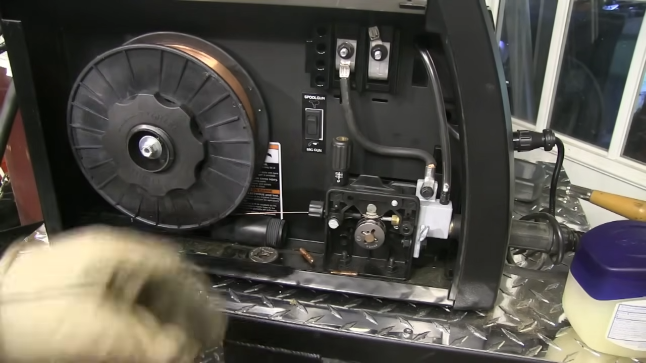
The Wire Feed Speed Calculation Formula
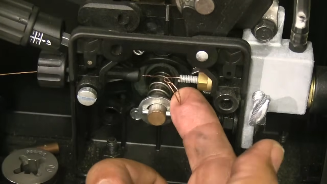
Wire Burn-Off Factors by Diameter
Wire Diameter
Burn-Off Factor
.023″ / .024″
3.5
.030″
2.0
.035″
1.6
.045″
1.2
Step-by-Step Calculation Example
1/8″ = 0.125″ = 125 thousandths
Burn-off factor = 2.0
Wire speed = 125 × 2.0 = 250 IPMAnother Example: .035″ Wire on 3/16″ Plate
3/16″ = 0.1875″ = 187.5 thousandths (round to 188)
Burn-off factor = 1.6
Wire speed = 188 × 1.6 = 300 IPMWhy This Formula Works

Complete Wire Feed Speed Chart (All Wire Sizes)
Wire Feed Speed Chart – .030″ Wire (Most Common)
Material Thickness
Thousandths
Amps Needed
Wire Speed (IPM)
18 gauge
48
48
96
16 gauge
60
60
120
14 gauge
75
75
150
1/8″
125
125
250
3/16″
188
188
376
1/4″
250
250
500
Wire Feed Speed Chart – .023/.024″ Wire (Thin Material)
Material Thickness
Thousandths
Amps Needed
Wire Speed (IPM)
18 gauge
48
48
168
16 gauge
60
60
210
14 gauge
75
75
263
1/8″
125
125
438
Wire Feed Speed Chart – .035″ Wire (All-Purpose)
Material Thickness
Thousandths
Amps Needed
Wire Speed (IPM)
1/8″
125
125
200
3/16″
188
188
301
1/4″
250
250
400
3/8″
375
300*
480
Wire Feed Speed Chart – .045″ Wire (Thick Material)
Material Thickness
Thousandths
Amps Needed
Wire Speed (IPM)
3/16″
188
188
226
1/4″
250
250
300
3/8″
375
300
360
1/2″
500
350
420
Welding
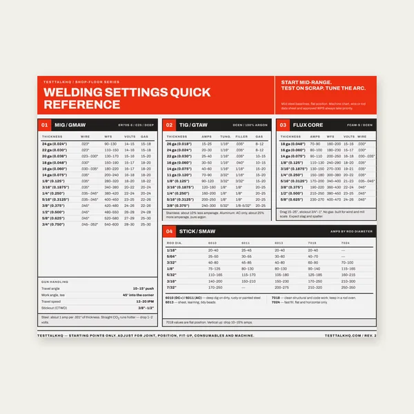
Welding Reference Card

Complete Welding Settings Guide
Welding Job Estimator
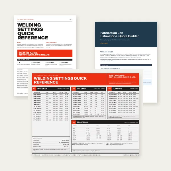
Welding Complete Bundle
Recommended MIG wire & accessories
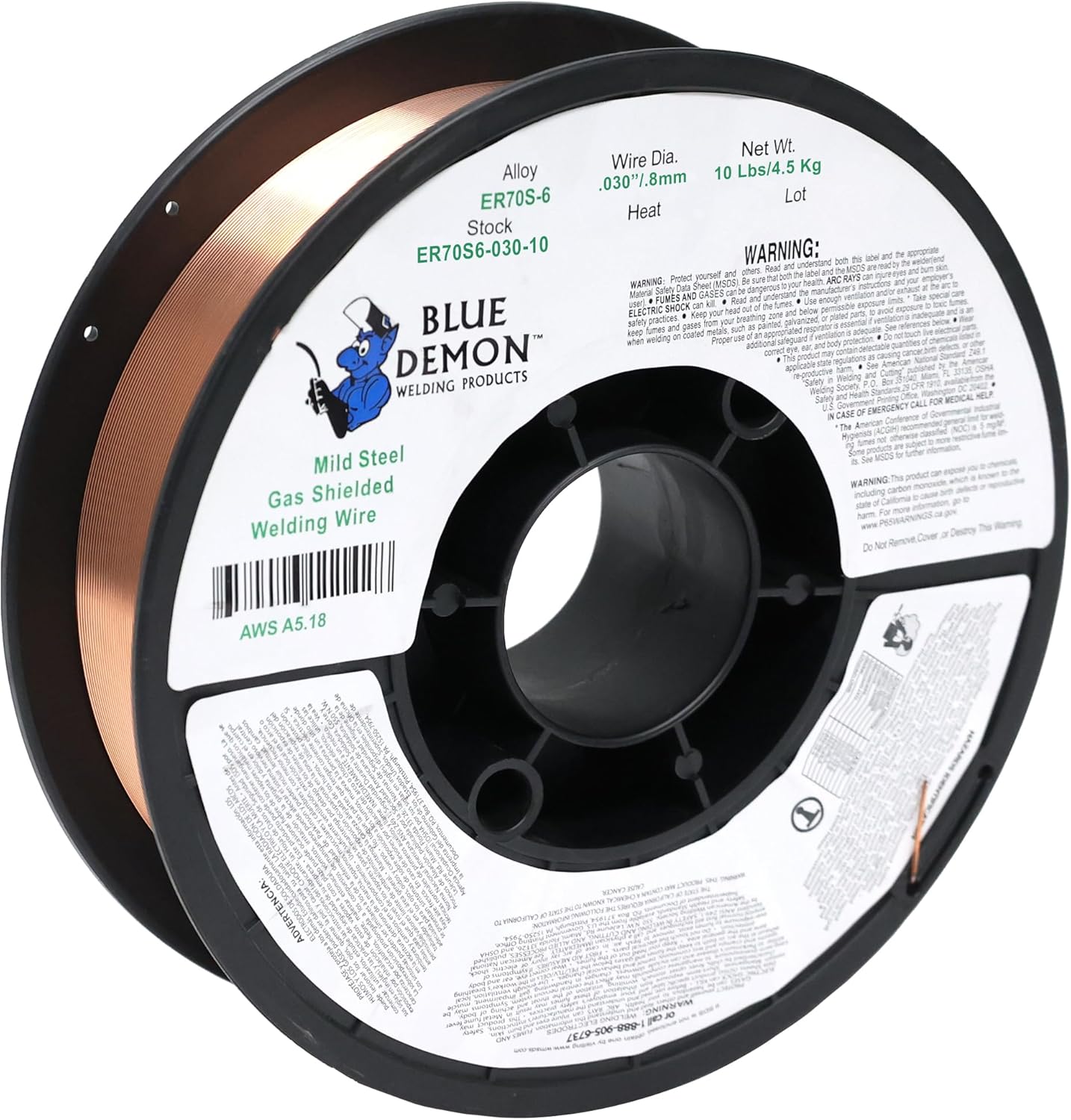
Blue Demon ER70S-6 .030″ Wire 10lb
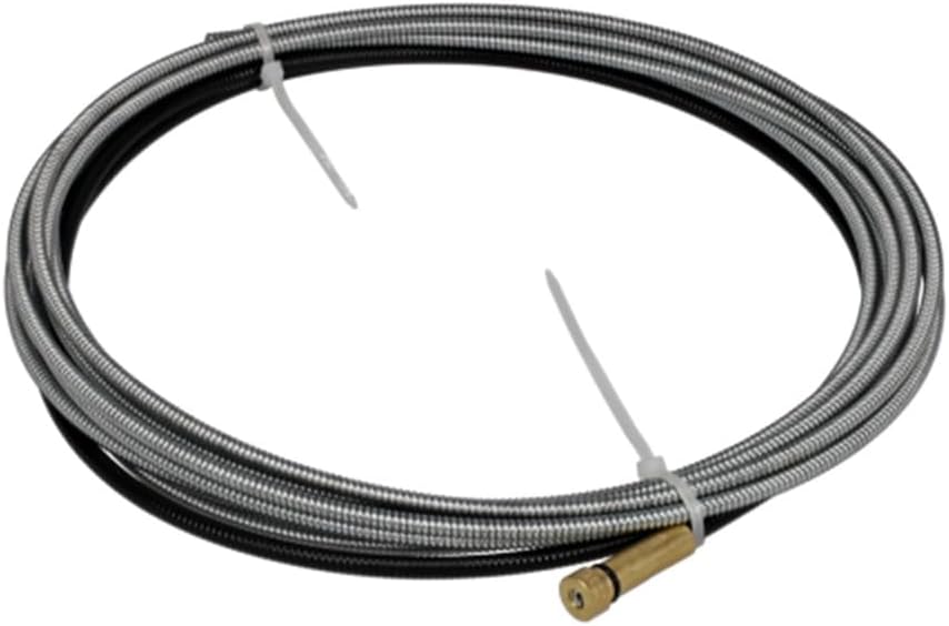
Startech Weld MIG Wire Liner Kit
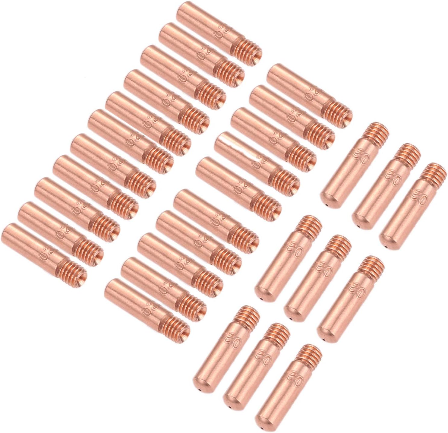
MIG Contact Tips Multi-Size Pack
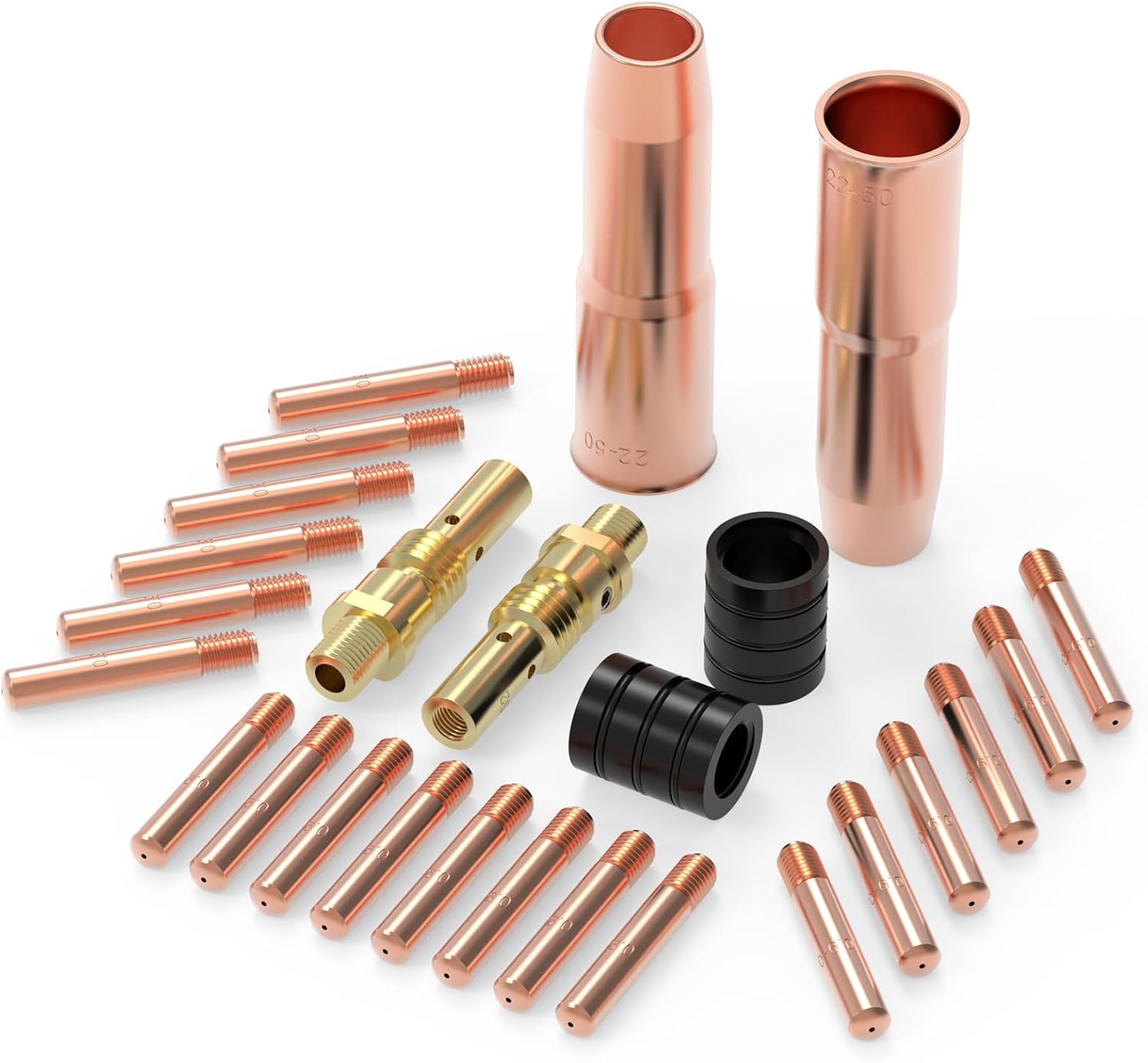
Yeswelder MIG Gun Complete Kit
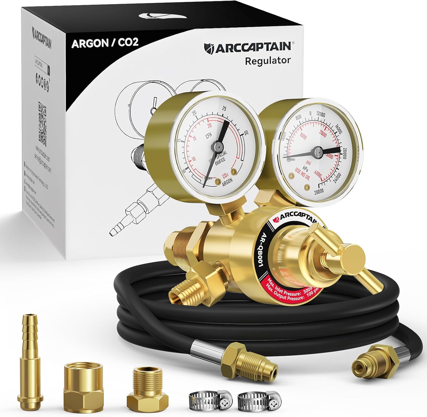
ARCCAPTAIN Argon/CO2 Regulator Kit
How Wire Diameter Affects Speed Settings
.023″ / .024″ Wire – Thin Material Specialist
.030″ Wire – The Universal Choice
.035″ Wire – Heavy Fabrication Standard
.045″ Wire – The Thick Plate Specialist
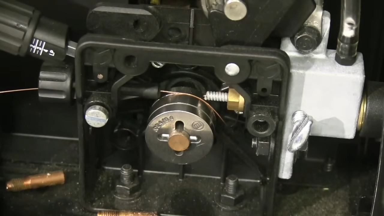
Wire Speed vs. Voltage: The Critical Relationship
What Wire Feed Speed Actually Controls
What Voltage Actually Controls
The Interaction: Why You Can’t Set One Without the Other
Practical Test: Changing Wire Speed While Voltage Stays Constant
The Set-Wire-Speed-First Method
Step 1: Calculate Wire Feed Speed
125 thousandths × 2.0 = 250 IPMStep 2: Set Wire Feed Speed on Machine
Step 3: Verify With the 6-Second Test
Step 4: Start Voltage VERY Low
Step 5: Weld, Listen, Adjust Voltage Up
Step 6: Fine-Tune for Position
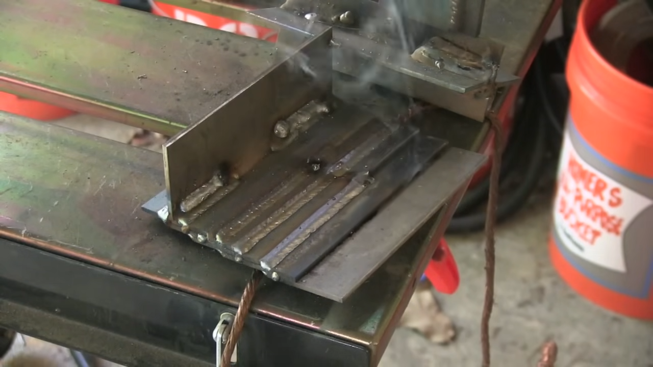
Recommended Settings by Material Thickness
18 Gauge Sheet Metal (0.048″)
Voltage: 14-15V
Amperage: ~48A
Gas flow: 15-20 CFH
Technique: Fast travel speed, push angle, minimal dwell time16 Gauge Sheet Metal (0.060″)
Voltage: 15-16V
Amperage: ~60A
Gas flow: 15-20 CFH
Technique: Steady travel, slight push angle14 Gauge Sheet Metal (0.075″)
Voltage: 16-17V
Amperage: ~75A
Gas flow: 18-22 CFH
Technique: Can slow down slightly, less burn-through risk1/8″ Plate (0.125″)
Voltage: 18-19V
Amperage: ~125A
Gas flow: 20-25 CFH
Technique: Standard travel speed, slight weave acceptable3/16″ Plate (0.188″)
Voltage: 19-20V
Amperage: ~188A
Gas flow: 22-25 CFH
Technique: Slower travel, watch for undercut on edges1/4″ Plate (0.250″)
Voltage: 20-22V
Amperage: ~250A
Gas flow: 25-30 CFH
Technique: May need preheat in cold weather, watch for incomplete fusionCommon Wire Speed Problems and Fixes
Problem: Bird-Nesting (Wire Tangled Behind Drive Rolls)
Problem: Inconsistent Wire Feed (Stuttering, Pulsing)
Problem: Wire Speed Seems Wrong vs. Dial Reading
Problem: Excessive Spatter Even at Correct Settings
Problem: Can’t Get Settings to Work for Vertical Uphill
Diagnostics and Technique Destinations
Frequently Asked Questions
What wire feed speed do I need for 1/8″ steel?
How do I measure wire feed speed without a digital readout?
What’s the difference between .030 and .035 wire feed speed?
Should I set wire speed or voltage first?
Why does my wire bird-nest with .023 wire?
Can I use the same wire speed for vertical as flat welding?
What wire feed speed do I need for aluminum MIG welding?
How does wire feed speed affect penetration?
What happens if wire feed speed is too high?
Can I calculate wire feed speed for stainless steel?
Conclusion: Wire Speed First, Voltage Second
Wire Gauge Calculator for Welders
Electrode/Wire Consumption Calculator
Shielding Gas Flow Rate Calculator
Wire Feed Speed Chart: Complete MIG Welding Settings Guide

MIG Welding Calculator
BEST VALUE
Best value
Essential
Consumable
Gun kit
Gas
MIG Welding Calculator