Calculators & guides only — no articles or blog noise.
Copper Pipe Expansion Loop Calculator
How far the run grows, and the developed length of tube that has to absorb it — from the Copper Development Association formula and Table 14.8
Embed this calculatorFree · no API key · keep the attribution link
Copy the snippet below to embed this calculator on your site. The attribution link must stay intact and dofollow (no rel="nofollow"). Browse all embeddable calculators
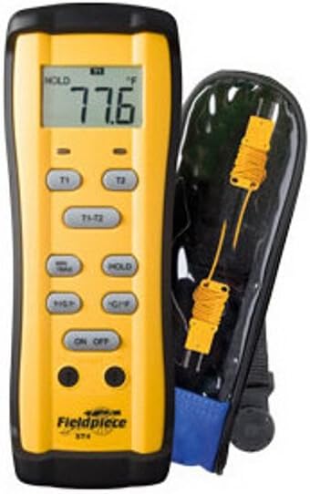
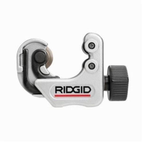
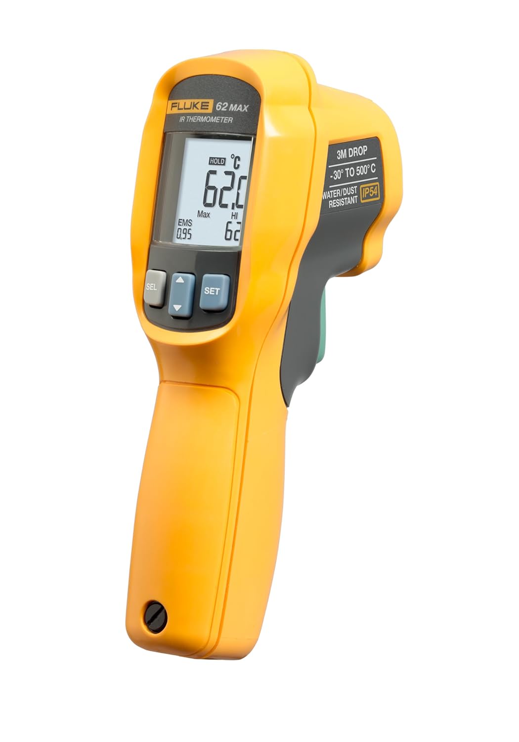
Two of the four inputs on this page are temperatures, and guessing them is how a loop ends up a third too small — the difference between an assumed 140°F and an actual 180°F is a third more movement. The rest of the job is physical: square cuts on the legs of the offset, and as few joints inside it as you can manage. These are the tools for both halves.
The temperature you are guessing
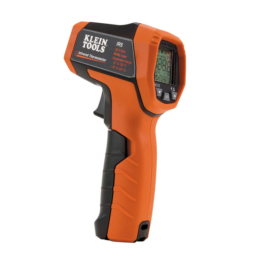
Klein Tools IR5 Dual‑Laser Infrared Thermometer
Reads the actual tube surface temperature, which is the input that matters
Dual laser frames the spot so you measure the pipe and not the insulation
Catches the case people miss: a recirculation return sitting near supply temperature
As an Amazon Associate, TestTalkHQ earns from qualifying purchases. Prices and availability can change.
The movement does not care how big the pipe is
The Copper Tube Handbook states the arithmetic in four lines, and the thing worth noticing is what is missing from it:
Temperature Rise (°F) × Length (feet) × 12 (inches per foot) × Expansion Coefficient (inches per inch per °F) = Expansion (inches)
There is no diameter in that expression. The handbook makes the point itself when it works the example: “the expansion of each 100 feet of length of any size tube heated from room temperature (70°F) to 170°F (a 100°F rise) is 1.128 inches.” Any size. A ½ in branch and a 4 in main in the same ceiling, on the same temperature swing, grow by the same amount.
What diameter changes is how hard that tube is to bend out of the way, and that is the second half of the problem. Here is the movement on its own, for the temperature swings that actually turn up on a job:
Temperature change
Per 10 ft
Per 25 ft
Per 50 ft
Per 100 ft
50°F (cold main to a warm room)
0.056 in
0.141 in
0.282 in
0.564 in
70°F (70 to 140°F domestic hot)
0.079 in
0.197 in
0.395 in
0.790 in
110°F (70 to 180°F hydronic)
0.124 in
0.310 in
0.620 in
1.241 in
130°F (70 to 200°F heating main)
0.147 in
0.367 in
0.733 in
1.466 in
Read the 110°F row. A 50-foot hydronic main moves five eighths of an inch. If that run is anchored at both ends and has nothing in it that can flex, five eighths of an inch of copper has to go somewhere, and the only places available are a bow between hangers, a groove worn into the tube where a strap holds it, or the solder cup of the nearest elbow.
Where the loop length comes from
The handbook gives the loop formula in general form, with four variables and no copper in it at all:
L = (1/12) √( 3 E (do e) / P )
where L is the developed length in feet in the expansion loop or offset, E is the modulus of elasticity in psi, P is the design allowable fiber stress of the material in flexure in psi, do is the outside diameter in inches, and e is the amount of expansion to be absorbed in inches. It is a guided cantilever in bending: you are deciding how long a piece of tube has to be before the deflection you are forcing on it stays inside an allowable bending stress.
Then the handbook substitutes copper into it: “For annealed copper tube: E = 17,000,000 psi, P = 6,000 psi. Thus, the developed length L is simply:”
L = 7.68 √(do e)
That 7.68 is worth checking, because checking it tells you the two constants are the only copper-specific thing in the formula. √(3 × 17,000,000 / 6,000) = 92.195, and 92.195 / 12 = 7.6830. The printed shortcut is the general formula with those two numbers already in it, and nothing else.
A number you can hold in your head. For 1 in tube (do = 1.125 in) absorbing exactly 1 in of expansion, L = 7.68 × √1.125 = 8.15 feet of tube in the loop. Eight feet of copper to swallow one inch. That ratio is what makes experienced installers break long runs into shorter anchored sections rather than build one enormous loop — and because L goes with the square root of the expansion, halving the run only shortens the loop by about 30 percent, not by half.
The formula and the table disagree, slightly, and always in the same direction
The handbook gives two routes to the same answer. The formula above is one. Table 14.8, Radii of Coiled Expansion Loops and Developed Lengths of Expansion Offsets, is the other: eight rows of expected expansion against thirteen nominal sizes, giving a coil radius and a developed length for each. The text introduces the formula as the alternative — “Alternatively, the necessary length of tube in an expansion loop or offset can be calculated using the formula” — which implies the two should agree. Run both at all 104 cells and they do not, quite:
Nominal size
Expansion
Table 14.8 L
Formula L
Formula is
½ in
1 in
70 in
72.9 in
+4.1%
1 in
1 in
94 in
97.8 in
+4.0%
2 in
2 in
183 in
190.1 in
+3.9%
4 in
4 in
361 in
374.5 in
+3.7%
Across every one of the 104 published cells the formula asks for between 3.1% and 5.1% more tube than the table does, averaging 3.9%, and it is never shorter. Solve the formula backwards for the fiber stress the table cells imply and the reason appears: the table behaves as though P ≈ 6,480 psi (a tight band from 6,375 to 6,622 across all 104 cells) rather than the 6,000 psi printed with the formula. Put 6480 into the fiber stress box on this page and the two routes agree to about a tenth of a percent.
Practically: the difference is a couple of inches on a domestic branch and about a foot on a big main. The calculator prints both and recommends the longer. Nobody has ever been called back because a loop had four percent more tube in it than it needed.
And one relationship that is not published anywhere. Table 14.8 gives a coil radius and a developed length for every cell, and they are the same number twice: the coiled loop is a full circle, so the developed length is its circumference and R = L / 2π. Checked against all 104 pairs, no cell deviates by more than the rounding of the published radius to the nearest whole inch. That is how this page converts a developed length into a radius you can roll to — derived and verified, not published as a formula.
Anchors, guides, and the mistake that wastes the whole loop
Every number above describes a length of tube held at both ends. That makes the position of the anchors the most important decision on the job, and it is the one most often never actually made.
An anchor is a clamp that stops the tube dead and transfers the load into the structure. It defines the ends of the run. All of the growth between two anchors has to be absorbed by what you put between them.
A guide carries the weight and keeps the pipe in line while letting it slide lengthways. Hangers, J-hooks, clevis hangers and rollers are guides.
An accidental anchor is a strap pulled tight, a hole through a plate that is the same size as the pipe, a pipe grouted into a wall, or a fitting hard against a joist. It behaves exactly like a designed anchor except that nobody calculated for it.
The handbook’s support intervals are for guides: “unless otherwise stated in plumbing codes, drawn temper tube requires support for horizontal lines at about 8-foot intervals for sizes of 1-inch and smaller, and at about 10-foot intervals for larger sizes. Vertical lines are usually supported at every story or at about 10-foot intervals.” For annealed coil the handbook asks for support at least every 8 feet horizontally and 10 feet vertically. On vertical lines it adds the detail that matters on a tall building: “for long lines where there are the usual provisions for expansion and contraction, anchors may be several stories apart, provided there are sleeves or similar devices at all intermediate floors to restrain lateral movement.”
The failure this prevents. A perfectly sized loop in the middle of a run does nothing if the tube is pinned either side of it. The movement never reaches the loop; it concentrates at whatever pinned it. If you take one thing from this page, take this: decide where the two anchors are, make them real, and make sure everything between them can slide.
What this calculation does not tell you
Four limits worth being explicit about, because each one is a different job.
There is no “you do not need a loop” threshold here, because the handbook publishes none. No run length, no temperature rise and no amount of expansion below which compensation may be left out. Short runs, flexible layouts with changes of direction that act as natural offsets, and runs anchored at one end only are all genuinely different cases, and that judgement belongs to the designer and the authority having jurisdiction. This page gives you the movement and the required length and stops there.
It is not a force calculation. The thrust that a restrained run puts into an anchor is a restraint analysis the handbook does not provide, and it is the number a structural engineer needs for a heavy main.
It is copper only. PEX, CPVC, PVC and PE move several times as far per degree and have their own published offset data from each manufacturer. Changing the modulus box does not convert this into a plastics tool, because the coefficient at the top of the calculation would be wrong too.
Expansion of the pipe is not expansion of the water. Heating trapped water in a closed system raises pressure rather than length, which is a thermal expansion tank and relief valve question — see the expansion tank sizing calculator. The two problems get confused constantly because they share a word.
The same physics turns up in other trades with different numbers and different details: a standing seam roof panel has exactly this problem and solves it with sliding clips rather than loops, which is what the metal roof thermal expansion calculator works through.