
How to measure the cycle on a machine that is already running, and which of the three fixes is the right one

Two different complaints that sound identical
“My compressor runs all the time” and “my compressor keeps kicking on” get said in the same breath, by the same person, about the same machine. They are different faults with different fixes, and the arithmetic separates them cleanly.
Starts per hour is how often the motor has to pay the starting load. It is governed by how much air you store and how wide a pressure band you store it over. A bigger tank fixes it.
Duty cycle is what fraction of the hour the motor runs. It is governed by demand against capacity, and — this is the part that surprises people — a bigger tank does absolutely nothing for it.
Both come out of four short formulas published by the Compressed Air & Gas Institute, and this guide is about measuring them on a machine that is already in front of you rather than specifying one from scratch.
The four formulas, and what each input has to be
CAGI’s March 2024 technical paper Using Air Storage to Balance Capacity in a Reciprocating Compressor Installation gives the whole chain:
Gallons ÷ 7.48 = Cubic Feet
Added Storage = CF × ΔP ÷ 14.7
Drawdown = Added Storage ÷ Demand
Pump Up = Added Storage ÷ (Capacity − Demand)
Cycle time is drawdown plus pump-up. Starts per hour is sixty divided by the cycle. That is it — but three of the four inputs are routinely wrong, and a wrong input produces a confident wrong answer.
| Input | Where people get it wrong | What to use instead |
|---|---|---|
| Capacity | Taking piston displacement off the box, or a CFM figure quoted at 90 PSI for a machine running at 175 | Delivered ACFM at the pressure you actually run. CAGI: “PD at intake port will always be larger than ACFM at the discharge port”, and ACFM “is the true measure” |
| Demand | Adding up full-load tool ratings, and forgetting leaks entirely | The average over the period you care about, leaks included. CAGI’s own example: a 1/2 in impact averages 4.2 CFM against 22 CFM at full load |
| Storage | Counting the tank only | Tank plus any piping that stays pressurised with it. CAGI counts both and its example carries 2 CF of pipe against a 16 CF tank |
| Pressure band | Trusting the label on the switch | The gauge reading at the instant the switch trips, both ways. Switches drift, and the whole answer is the difference between two numbers |
Measuring it: a stopwatch and ten minutes
You do not need the formulas to get the two headline numbers off a running machine. You need the normal shop load running and something that counts seconds.
- Let the system settle. Run whatever the normal load is for a few minutes so you are not measuring a cold-start fill.
- Time the pump-up. From the instant the motor starts to the instant it stops. That is your loaded time.
- Time the drawdown. From that stop to the next start. That is your off time.
- Add them. That is the cycle. Sixty divided by it is starts per hour.
- Divide. Pump-up divided by cycle is the duty cycle.
- Repeat three to five times and average. Real demand is lumpy, and one cycle is not a measurement.
While you are there, read the two switch pressures off the gauge at the moment it trips. Those two numbers plus the tank size let you work backwards to what the system thinks your demand is — and comparing that with what you believe your demand is often finds a leak nobody was looking for.
Worked example, straight from CAGI’s table. A 35 CFM compressor, 10 CFM of average demand, 16 CF of receiver plus 2 CF of pipe, switch set 125 cut-in / 150 cut-out.
Storage = 18 × 25 ÷ 14.7 = 30.6 CF of free air.
Drawdown = 30.6 ÷ 10 = 3.06 min off.
Pump up = 30.6 ÷ (35 − 10) = 1.22 min running.
Cycle = 4.28 min, so 14.0 starts per hour — double the recommended limit.
Duty cycle = 1.22 ÷ 4.28 = 28.6%, which is also exactly 10 ÷ 35.
The limit, and why it is a band rather than a line
CAGI’s storage paper gives the number plainly: “due to the brief starting load placed on an electric motor, it is commonly recommended that the motor start no more than seven times per hour.”
Its buyer’s guide frames the same figure as a control decision instead of a pass/fail test: “if the compressor starts more than six to eight times per hour, you should operate constant speed control or choose a larger compressor. If the compressor starts less than six times per hour, start/stop control should be sufficient.”
So six to eight starts an hour is the zone where plain start/stop stops being the right answer. Below it you are fine. Above it you are choosing between a bigger machine, a different control scheme, or one of the storage fixes below. That choice is its own decision, covered in start/stop vs constant speed control.
Any trade

Contractor Job Estimator
Price remodels and GC work, then send a quote with no internal numbers.
Excel or Google Sheets. Best on a computer.
$29.00
BuyCheckout opens in a new tab.
What the three fixes actually cost
Storage and pressure band are the two fixes you can buy; the third is a switch setting you verify with a gauge. Leak hunting is cheaper than all of them and moves the duty cycle as well as the cycling.
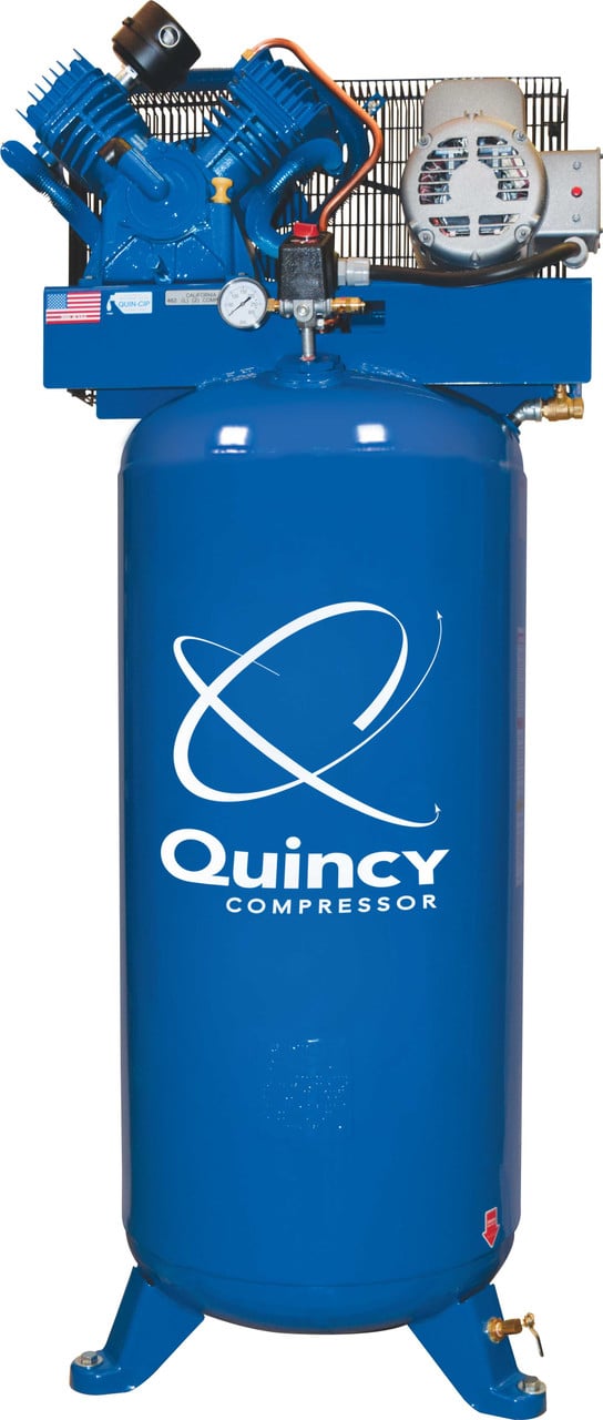
Quincy QT‑54 5 HP 60 Gallon Two‑Stage
- 60 gallons is 8.02 CF of receiver before any piping is counted
- Two-stage pumps run a wider pressure band, which is fix two built in
- Pressure-lubricated pumps are the ones rated for long loaded runs
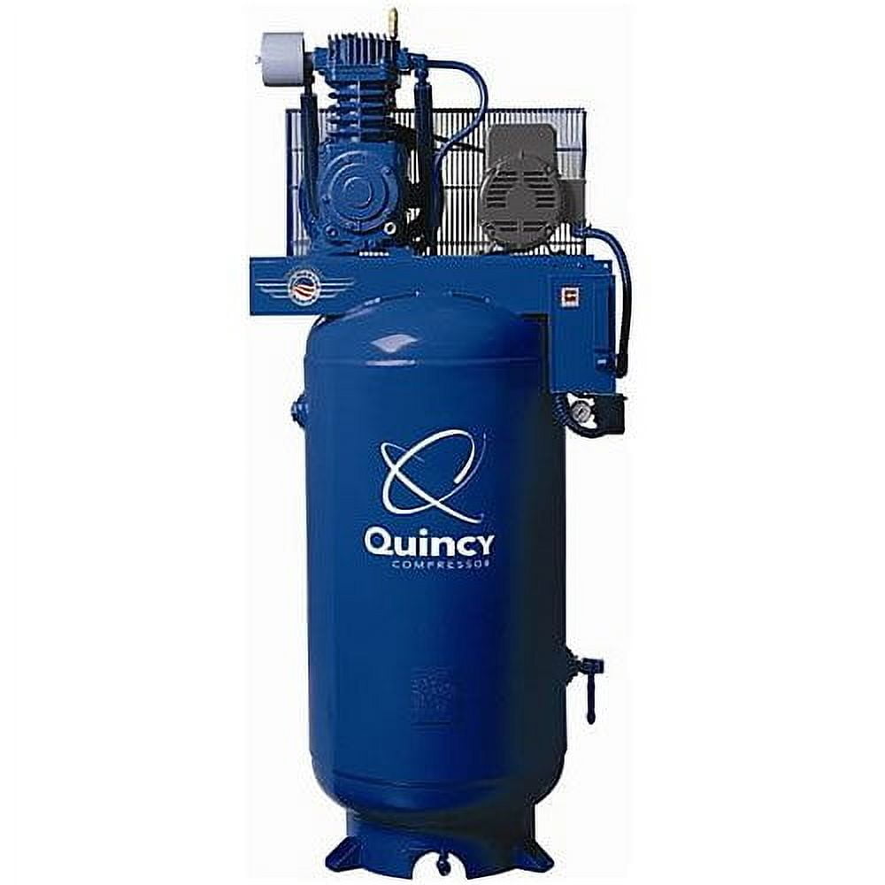
Quincy QT‑7.5 7.5 HP 80 Gallon
- 80 gallons is 10.70 CF — a third more free air per cycle than a 60
- More delivered CFM moves the worst-case demand point up with it
- Where demand has outgrown the pump, storage alone will not save it

LE LEMATEC Regulator & Gauge 0‑150 PSI
- Every cycle figure hangs on the actual cut-in and cut-out, not the label
- A drifted differential is a short-cycle you can often fix for free
- Set the regulator to what the tool needs, not to what the tank holds
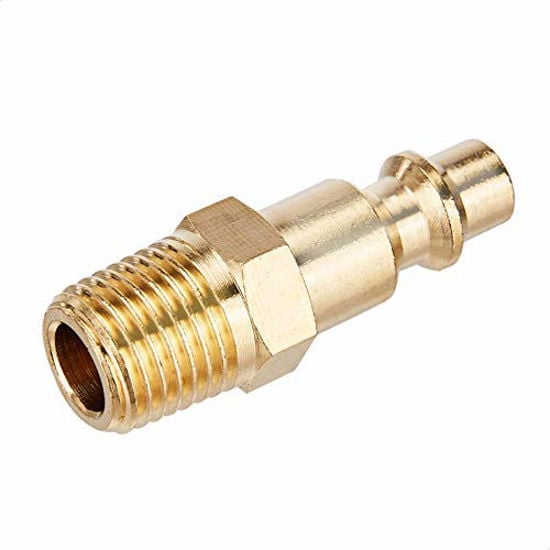
Quick‑Connect Brass Coupler & Plug Kit
- Leaks are demand, and demand sets both the duty cycle and the cycling
- Worn couplers are the most common hidden CFM on any shop air system
- CAGI calls under 10 percent leakage well maintained, over 30 percent common
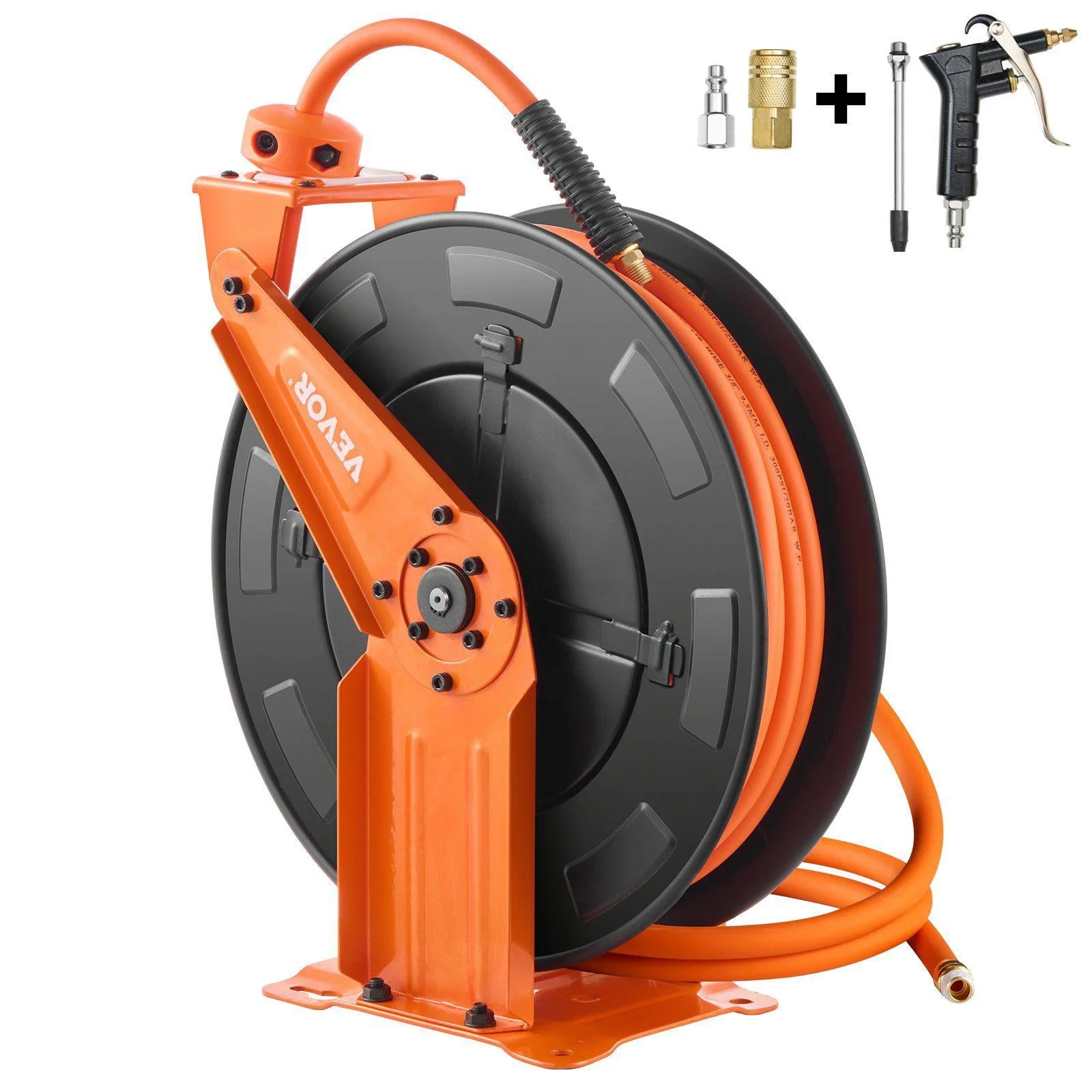
Relhost Retractable Air Hose Reel 65 ft x 3/8 in
- CAGI counts piping as storage — a long fat main genuinely lengthens the cycle
- Undersized hose is pressure drop, which pushes the regulator and switch up
- Storage near a heavy intermittent user is CAGI’s fix for demand gulps
As an Amazon Associate, TestTalkHQ earns from qualifying purchases. Prices and availability can change.
Why a bigger tank cannot lower your duty cycle
This falls out of CAGI’s own formulas and is worth doing on paper once, because it settles a great many arguments. The duty cycle is:
duty = pump up ÷ (pump up + drawdown)
Substitute the published expressions. With S for storage, C for capacity and D for demand, pump-up is S ÷ (C − D) and drawdown is S ÷ D. The storage S appears in both, top and bottom, so it cancels completely:
duty = D ÷ C
Exactly, with no storage term and no pressure term left in it. A 15 CFM machine against 5 CFM of demand runs one third of the hour on a 20-gallon tank and one third of the hour on a 240-gallon tank. What the tank changes is whether that twenty minutes arrives as three long runs or thirty short ones.
Which gives you a clean diagnostic split:
| The complaint | What it really is | What moves it | What does not |
|---|---|---|---|
| “It starts too often” | A cycling problem | More storage, wider pressure band, alternating machines | More CFM barely helps and can make it worse |
| “It runs too much of the day” | A capacity or demand problem | More delivered CFM, or less demand — usually less leakage | A bigger tank does nothing at all |
The worst demand your shop can produce is half your capacity
Write starts per hour as a function of demand and something useful appears:
N = 60 × D × (C − D) ÷ (S × C)
That is a downward parabola in demand. At zero demand it is zero, because nothing drains the tank. As demand climbs toward capacity it falls back toward zero again, because the pump-up time stretches out and the motor stops stopping. In between it peaks, and it peaks exactly at D = C ÷ 2, where N = 15 × C ÷ S.
Light demand barely cycles a compressor. Heavy demand does not cycle it either — it just runs it. The cycling damage happens in the middle, which is precisely where a normal busy afternoon sits.
Two practical consequences:
- Sizing storage for today’s average is fragile. If your demand is well under half of capacity, demand growing will make the cycling worse before it makes it better. Size the receiver for the midpoint and you never have to revisit it.
- Buying more capacity can increase cycling. Fit a bigger pump to the same tank and you have moved the worst-case point up and shortened every pump-up. If your demand was already near the old midpoint, a bigger machine on the old receiver can start more often, not less.
CAGI’s three fixes, with what each one costs you
The storage paper does not stop at the diagnosis. It names three remedies and works two of them numerically on its 35 CFM example.
| Fix | CAGI’s worked result | The catch |
|---|---|---|
| 1. Add storage | 16 CF of tank doubled to 32 CF: 14.02 starts/hr down to 7.42 | Floor space and money, and a longer fill from cold. No operating penalty at all. This is the clean fix. |
| 2. Widen the pressure band | 150/125 changed to 175/120 on the original tank: 14.02 down to 6.37 | Hard-capped by the pump’s rated pressure, the relief valve and the switch’s adjustment range. Higher pressure also means more leakage and more energy per CFM. |
| 3. Alternate a second machine | “The load on each individual compressor motor is limited to about seven starts per hour” | Two machines to maintain, and it only helps if the alternation really happens. It does not change the system cycle — it shares the starts. |
There is a fourth lever CAGI does not list here, and it is usually the first one worth pulling: reduce demand. Leaks are demand that runs every hour the system is pressurised, and cutting them moves the duty cycle and the starts per hour together. CAGI’s sizing brief puts a well-maintained system under 10 percent leakage and notes it is “not uncommon to find systems with leakage rates that exceed 30 percent of total supply.” A third of your compressor’s output going into nothing will cycle it around the clock.
Its sizing FAQ gives the test: isolate production, raise the system to cut-out, shut the compressor off, and time the pressure decay — with the caveat that you should “only be allowed to drop 10 PSIG as the leak rate will change with changes in pressure.” Turn that into a CFM figure with the leak calculator before you price a receiver.
Piping is storage, and where you put it matters
CAGI counts the distribution main in the storage term explicitly: “the capacity of compressed air piping also contributes to the total capacity of the air storage system.” Its worked example carries 2 CF of pipe alongside a 16 CF receiver — an eleven percent addition that lands straight on the cycle time.
Rough internal volumes, to help you put a sensible number in rather than guessing:
| Nominal size | Volume per 100 ft | Equivalent receiver |
|---|---|---|
| 1/2 in | about 0.11 CF | under 1 gallon |
| 3/4 in | about 0.21 CF | about 1.5 gallons |
| 1 in | about 0.37 CF | about 2.8 gallons |
| 1-1/2 in | about 0.78 CF | about 5.8 gallons |
| 2 in | about 1.4 CF | about 10.5 gallons |
Those are approximate internal volumes at those nominal sizes, offered to get you in the right order of magnitude rather than to replace measuring your own run. Count only pipe that stays pressurised with the receiver — anything behind a closed valve or a check valve is not storage. And note the double benefit: a generously sized main is more storage and less pressure drop, which is why sizing the main properly keeps paying back.
When this guide does not apply to your machine
Everything above assumes start/stop control: the motor runs only while the pump is making air and stops at cut-out. That is how essentially every reciprocating shop compressor works, and it is the machine CAGI’s paper is about.
On a constant speed machine the motor keeps turning and the pump cycles between compressing and free-wheeling, so counting motor starts measures almost nothing — the whole point of that control scheme is to stop the motor starting. On a variable speed machine output modulates to track demand and it may never cycle at all. In both cases the duty cycle still tells you how hard the machine is working; the starts figure does not.
Technology matters here too. CAGI notes that reciprocating compressors suit intermittent duty — “the full power of the compressor is available when needed” and it shuts off between demands — while “rotary screw, rotary vane, scroll, centrifugal, and axial compressors are all designed to run best fully loaded all of the time” and running them at low duty cycles “is not optimal for reliability.” That is the reverse of the reciprocating case, and it is a different purchase conversation: see rotary screw vs piston.
Two smaller assumptions worth stating. Demand is treated as steady across the cycle, which it never quite is — a shop with one big intermittent user is better analysed as that user plus a baseline. And the receiver is treated as isothermal, which CAGI also does deliberately: its paper “discusses principles using a constant air temperature.” Air heats on compression and cools in the tank, so a hot pump on a cold morning cycles slightly differently from the arithmetic.