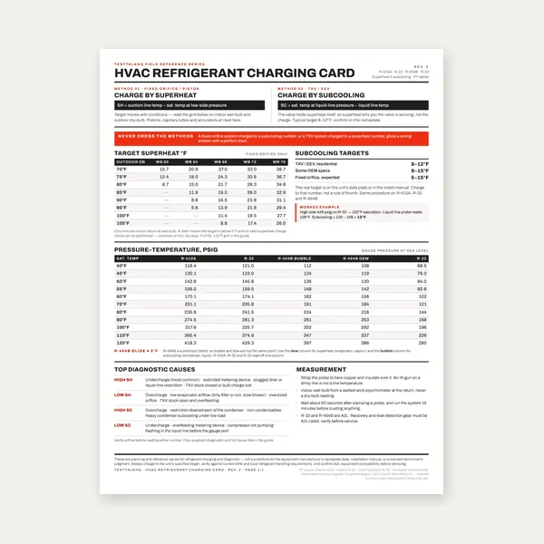
HVAC Refrigerant Charging Card
$3.99
BuyWhat the coil is actually delivering — total, sensible and latent BTU from four temperatures and an airflow
A dry-bulb split across the coil tells you about half the story, and on a humid day it is the less interesting half. Air leaving an evaporator is doing two jobs at once: dropping the temperature, and wringing water out. Only one of those shows up on a thermometer. Put a wet bulb on the return and the supply as well and the whole picture appears — total capacity, how much of it is sensible, how much is latent, and the ratio between them. That ratio is the number that tells you whether the equipment matches the building it is in.
This works it the long way, from the ASHRAE psychrometric equations, with the barometric pressure corrected for your elevation. No standard-air shortcut, no assumed density, no chart reading. It also shows you what the familiar 1.08 and 4.5 constants would have told you, so you can see exactly how much the shortcut costs where you are standing.
$3.99
Buy
$12.99
Buy
$29.00
Buy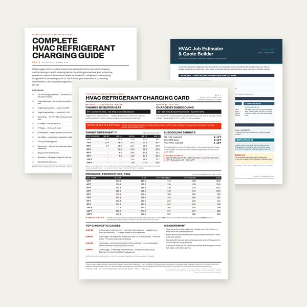
$39.00
BuyCheckout opens here — you stay on this page.
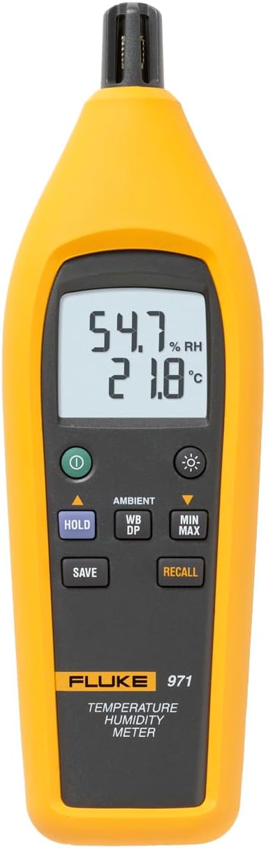
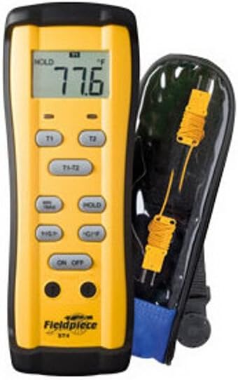
Six numbers go in and every figure above comes out of them. Airflow scales the whole answer, and the supply wet bulb sets the latent half of it — half a degree of error there moves the latent capacity by around a fifth. These are the instruments that produce those six numbers, and on this page they matter more than the arithmetic does.
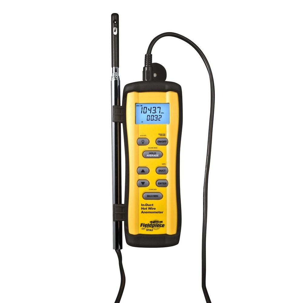
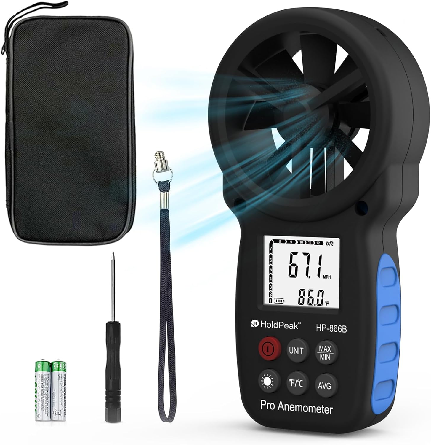
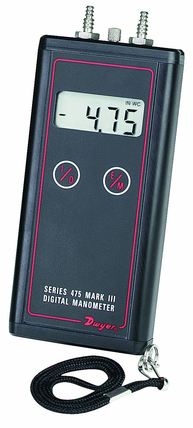
As an Amazon Associate, TestTalkHQ earns from qualifying purchases. Prices and availability can change.
Air coming off a cooling coil has had two different things done to it. Its temperature has been lowered, and if the coil was below the entering air's dew point, water has been condensed out of it. A thermometer sees the first. It is completely blind to the second.
That matters because the second one is not a rounding error. On a humid day a residential coil can be spending a quarter of its total output on condensing water, and none of that shows up in a dry-bulb reading. Two systems with an identical 21 °F split can be delivering capacities that differ by thousands of BTU an hour, because one is running wet and the other is not.
Ed Janowiak, who runs HVAC design education for ACCA, puts the case for the enthalpy method plainly:
The extra measurement is one more temperature at each location. What you get back is the total capacity, the split, and a number you can compare against the water actually running out of the drain.
Everything on this page is out of one chapter: ASHRAE Handbook—Fundamentals, chapter 1, Psychrometrics. Nothing is fitted, nothing is a rule of thumb, and there is no coefficient anybody tuned.
This is the first thing the calculator does and the first thing most field calculations skip. Pressure sets density, density sets how many pounds of air a CFM represents, and the capacity equation works in pounds.
Humidity ratio is pounds of water per pound of dry air. It is the only moisture measure that stays put when you heat or cool air, which is why every step below is built on it rather than on relative humidity.
If you entered relative humidity instead, the route is shorter: the vapour pressure is that fraction of the saturation pressure, and the same eq (20) turns it into a humidity ratio.
Those three constants in the enthalpy equation are not arbitrary: 0.240 is the specific heat of dry air, 0.444 the specific heat of water vapour, and 1061 the enthalpy of saturated water vapour extrapolated back to 0 °F. All three are inch-pound conversions of the SI figures ASHRAE prints alongside them.
The second term is the condensate credit, and it is the part most field calculations drop. Water leaving the coil as liquid at the supply air temperature takes some enthalpy with it, and the coil never had to remove that. It is worth about 1% of the total — small, exact, and free to include.
Cool the air at constant moisture content first, then remove the moisture at constant temperature. Substitute the enthalpy equation into both legs and the two parts sum to exactly the total enthalpy difference — no residual, no fudge. The sensible heat ratio is then just their ratio, which is also, as CED Engineering's psychrometrics course puts it, “defined by the slope of the line connecting the two points” on a psychrometric chart.
Every technician meets these before they meet a psychrometric equation:
They are not magic numbers. CED Engineering's course derives all three in four lines, and it is worth seeing because the derivation is also the list of assumptions:
So the whole family rests on one number: 0.075 pounds per cubic foot, which is 13.333 cubic feet per pound. That is dry air, at sea level, at around 70 °F. Three assumptions, and a job site rarely satisfies any of them.
| Air condition | Real specific volume | Error in the 4.5 constant |
|---|---|---|
| 80 °F / 67 °F WB, sea level (AHRI rating condition) | 13.85 ft³/lb | 3.7% high |
| 75 °F / 62 °F WB, sea level | 13.67 ft³/lb | 2.5% high |
| 78 °F / 65 °F WB, 2,500 ft | 15.12 ft³/lb | 11.8% high |
| 80 °F / 67 °F WB, 5,280 ft (Denver) | 16.90 ft³/lb | 21.1% high |
Specific volumes computed from ASHRAE eq (26) at the barometric pressure eq (3) gives for each elevation. The error column is how much more air the 4.5 constant thinks you are moving than you actually are.
None of this makes the constants useless. For a load estimate, where the inputs are assumptions anyway, they are fine and they are fast. For a measurement you are about to make a warranty claim or a replacement recommendation with, they are the wrong tool.
SHR is the fraction of the coil's total output that goes into lowering temperature. An SHR of 0.80 means four-fifths of the work is sensible and a fifth is dehumidification. An SHR of 1.00 means the coil is bone dry and removing no water at all.
Two things set it, and they pull in opposite directions:
That second one is the lever a technician actually has, and it is why blower speed is a dehumidification control and not just an airflow control.
ANSI/AHRI Standard 210/240 rates cooling capacity at a specific condition, and it is printed in the standard's own test table:
| Test | Entering indoor unit | Entering outdoor unit |
|---|---|---|
| A test (required) | 80.0 °F DB / 67.0 °F WB | 95.0 °F DB / 75.0 °F WB |
| B test (required) | 80.0 °F DB / 67.0 °F WB | 82.0 °F DB / 65.0 °F WB |
Reproduced from the cooling test conditions table of ANSI/AHRI Standard 210/240-2017.
If your return air is at 75 °F and 50% relative humidity on a mild day, the coil has less to work with than the rating condition gives it, and a measured capacity below the nameplate is expected rather than alarming. The calculator prints your conditions next to AHRI's so the mismatch is visible, and it deliberately does not apply a correction factor — there is no general one, and the manufacturer's expanded performance tables exist precisely because there isn't.
Three inputs carry almost all of the uncertainty, and they are not equally to blame.
ASHRAE publishes its psychrometrics twice over. There is a set of perfect-gas relations — the equations above, the ones intended for calculation — and there is Table 2 and the printed psychrometric chart, which are computed from an exact formulation carrying an enhancement factor that corrects for dissolved gases, the pressure effect on liquid water, and vapour–air interaction.
The two disagree slightly. The enhancement factor runs about 1.004 to 1.005 over normal HVAC temperatures, so a humidity ratio read off a chart at saturation comes out roughly 0.4% higher than the one these equations produce. This calculator uses the perfect-gas relations, as PsychroLib and essentially every field tool does, because those are the equations ASHRAE prints for computing with. Carried through to a delivered-capacity answer the difference is at most about 0.3%, and under 0.003 on the sensible heat ratio.
That is far smaller than the airflow measurement it gets multiplied by, which is why nobody bothers with it. But it is the reason a chart reading and a computed figure differ in the third significant figure, and if you have been chasing that discrepancy, that is where it comes from.
Sensible heat ratio is the sensible cooling capacity of a coil divided by its total cooling capacity. An SHR of 0.75 means three-quarters of the coil's output is lowering air temperature and one-quarter is condensing water out of it. An SHR of 1.0 means the coil is dry and doing no dehumidification at all.
Measure airflow in CFM and the dry-bulb and wet-bulb temperatures entering and leaving the coil. Convert each pair to a humidity ratio and an enthalpy using the ASHRAE psychrometric equations at your local barometric pressure, work out the dry-air mass flow from the airflow and the specific volume, then multiply the mass flow by the enthalpy difference for total capacity and by the temperature difference and moist-air specific heat for sensible capacity. SHR is the second divided by the first.
A dry-bulb reading only sees sensible heat. Any heat the coil removes by condensing water out of the air — the latent capacity — is invisible to a thermometer. On a humid day that can be a quarter or more of the total, so a dry-bulb split alone cannot tell you what the equipment is actually delivering.
It is 4.5 multiplied by 0.24. The 4.5 comes from standard air at 0.075 pounds per cubic foot times 60 minutes per hour, which converts CFM to pounds per hour, and 0.24 is the specific heat of dry air. It therefore assumes dry air, at sea level, near 70 °F. At 5,280 feet the real air is around 21% less dense and the constant overstates capacity by that much.
No. Airflow scales the sensible and the total capacity by the same factor, so it cancels out of their ratio completely. A 10% error in CFM makes every BTU figure 10% wrong but leaves the sensible heat ratio exactly where it was. The BTU numbers need good airflow; the ratio does not.
Because the supply air computed wetter than the return air, which a cooling coil cannot do. In practice it is a measurement problem: a supply wet-bulb probe sitting in condensate or with a fouled wick, readings taken minutes apart while conditions moved, or a humidifier downstream of the coil and upstream of the probe.
Only as a sanity check. AHRI 210/240 rates capacity with 80 °F dry bulb and 67 °F wet bulb entering the indoor coil and 95 °F entering the outdoor unit. Cooler or drier return air than that legitimately gives less capacity. A reading below nameplate is a prompt to investigate, not a fault in itself, and the manufacturer's expanded performance data for your actual conditions is what settles the question.
Yes, more than most corrections. Capacity depends on the mass of air moved, not its volume. At 2,500 feet the same CFM carries about 12% less air by weight than at sea level, and at 5,280 feet about 21% less. A calculation done with sea-level constants at altitude is optimistic by that amount.
Water leaving the coil as liquid at the supply air temperature carries some enthalpy away with it, and the coil never had to remove that part. ASHRAE's cooling-and-dehumidification equation subtracts it from the total: the mass of water condensed multiplied by its liquid enthalpy. It is worth roughly 1% of total capacity — small, but exact and free to include.
Yes, and the calculator accepts either. Both are converted to a humidity ratio through the same ASHRAE equations, so neither route is more correct. In practice wet bulb is often the better field measurement for supply air, because supply air off a wet coil sits at 90% relative humidity or higher and that is where hygrometers are least accurate.