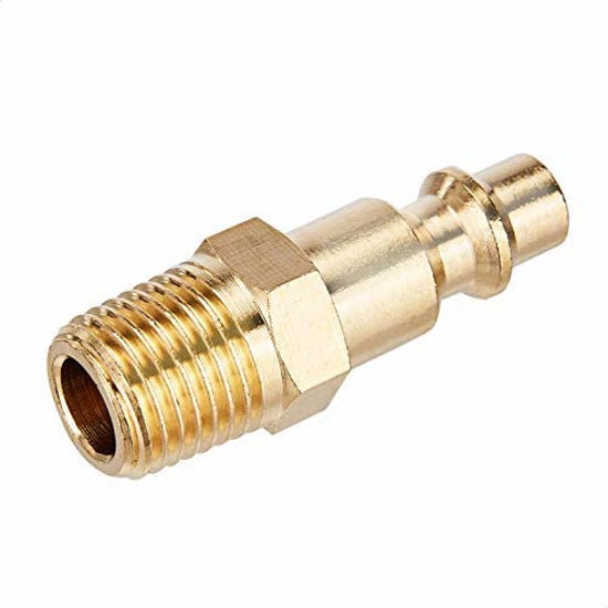
Quick Connect Brass Coupler Kit
- Undersized couplers throttle a correctly sized main
- Consistent fittings across every drop
- Brass body resists the corrosion that shrinks bore
Pressure drop, velocity, and the smallest pipe that actually holds your air
Shop air lines are almost never sized by calculation — they are sized by whatever fittings were on the shelf. Enter your flow, line pressure, run length, and fitting count to get the real Darcy-Weisbach pressure drop for every common pipe size, plus the smallest size that stays inside your drop target and a sane air velocity.

Pipe size only helps if the hardware at each end is not the new restriction. These are the parts that most often undo a correctly sized main.

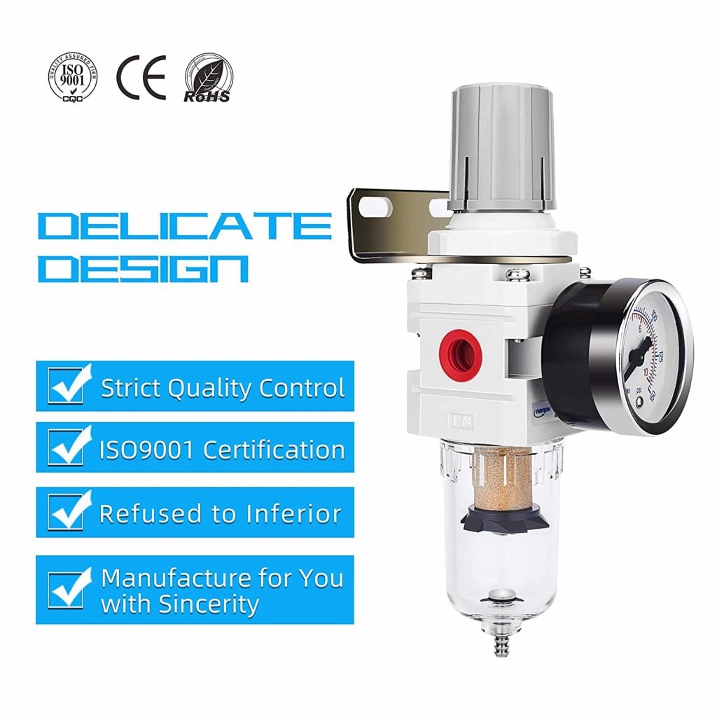
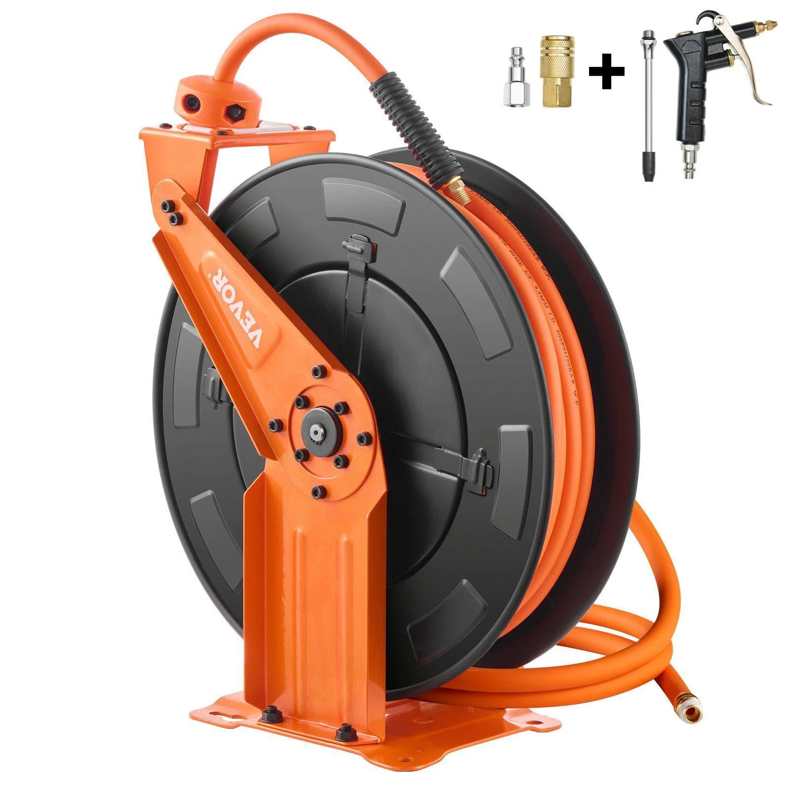
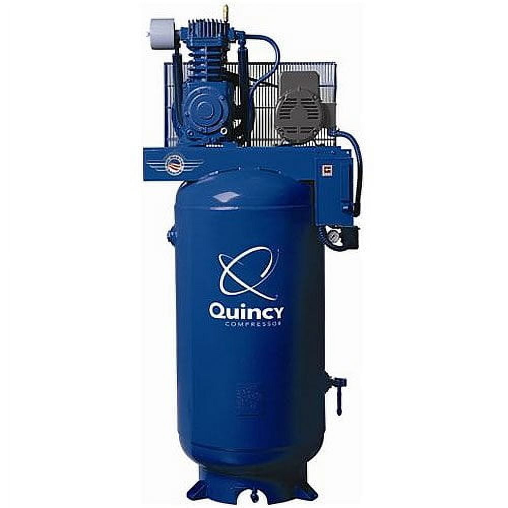
As an Amazon Associate, TestTalkHQ earns from qualifying purchases. Prices and availability can change.
Most shop air charts hide the physics behind a single lookup table that assumes one pressure, one temperature, and no fittings. This tool runs the actual pressure-drop equation on your numbers, then repeats it for every common pipe size so you can see where the cliff is.
Compressor and tool ratings are given in SCFM, referenced to standard conditions. The air inside a 100 psig line is compressed to roughly one eighth of that volume, and that compressed volume is what sets velocity. The ideal gas law does the conversion:
Standard conditions here are 14.7 psia and 68 °F, the ASME/CAGI reference. Absolute line pressure is your gauge pressure plus 14.7 psi.
An elbow is not free. Crane Technical Paper No. 410 gives each fitting a resistance expressed as a length-to-diameter ratio, so a fitting count converts to feet of equivalent pipe once the diameter is known:
| Fitting | L/D (Crane TP-410) | Equivalent length on 1" pipe |
|---|---|---|
| 90° standard elbow | 30 | 2.6 ft |
| 45° standard elbow | 16 | 1.4 ft |
| Tee, flow through run | 20 | 1.7 ft |
| Tee, flow through branch | 60 | 5.2 ft |
| Ball valve, full bore open | 3 | 0.3 ft |
| Gate valve, fully open | 8 | 0.7 ft |
That is why a compact run with a dozen elbows can lose more pressure than a long straight one. On 1 inch pipe, twelve 90° elbows add about 31 feet of equivalent pipe before a single foot of straight run is counted.
With the equivalent length known, pressure drop comes from the standard friction equation. Air density is evaluated at your actual line pressure and temperature from the ideal gas law, and the friction factor comes from the Swamee-Jain explicit form of the Colebrook-White equation using the pipe's relative roughness.
Roughness values are the standard Moody figures — 0.00015 ft for commercial steel, 0.000005 ft for drawn tubing such as copper. Viscosity is corrected for temperature with Sutherland's formula; it barely moves with pressure, which is why the correction is small.
Pressure drop alone will let you pick a pipe that technically passes but screams. High velocity picks up liquid water and scale off the pipe wall and carries it to the tools, and it makes drop legs and take-offs far less effective at separating condensate. Common design practice keeps mains at or below about 20 ft/s and branch lines below about 30 ft/s. The recommendation in this tool has to satisfy both your drop target and the 30 ft/s ceiling.
The widely used benchmark from the Compressed Air Challenge and the US Department of Energy's compressed air sourcebook is to hold total distribution loss to a few psi — commonly stated as no more than about 10 percent of discharge pressure, with 2 to 3 psi a normal design target from receiver to point of use. The reason is money, not comfort: every extra 2 psi of discharge pressure costs roughly 1 percent more compressor power, so a sloppy 10 psi distribution loss is about 5 percent on the electric bill forever.
Size by flow and distance, not by tank. A typical 5 HP single-stage unit delivers somewhere near 15 to 20 SCFM, and at 100 psig over a 100 ft run that comfortably fits in 3/4 inch Schedule 40 with room to spare. The same compressor feeding a 250 ft run with fifteen elbows is a different answer — run your own numbers above.
For pressure drop, yes, and oversizing costs nothing in energy. The real limits are cost, wall support, and the fact that a very large main holds a lot of stored air, which is usually a benefit. The practical answer is to never go below the calculated size and to step up one size if the run may grow.
Because the gauge is measuring static pressure at the receiver with no flow. Pressure drop only appears when air is moving. Check the pressure at the tool while the tool is running — that difference is what this calculator predicts.
No. PVC and CPVC become brittle with age and oil exposure and can shatter into fragments under stored air pressure. Manufacturers explicitly exclude compressed air service, and OSHA has cited its use. Use steel, copper, stainless, or a listed aluminium/composite air-pipe system.
Not meaningfully at the compressor, but undersized pipe makes the whole system behave like a smaller compressor at the tool. The compressor still fills the receiver at the same rate; it is the delivery to the point of use that is choked.