
Contractor Job Estimator
Price remodels and GC work, then send a quote with no internal numbers.
Excel or Google Sheets. Best on a computer.
$29.00
BuyThe flow coefficient a coupler, valve, regulator or FRL has to have before your tool gets the pressure it was rated at
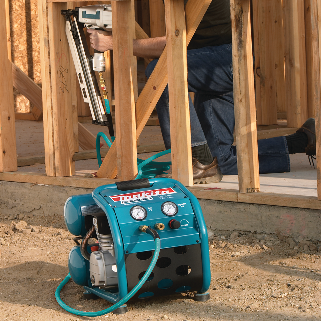
A half-inch impact wrench that will not break loose a lug nut is usually not a compressor problem. The compressor makes the air, the pipe carries it, and then it goes through a regulator, a filter, a quick coupler and a plug — four small holes in a row, each one throwing away pressure in proportion to the square of the flow through it. The number that describes how big each of those holes really is, independent of the thread stamped on it, is the flow coefficient: Cv. This works out the Cv your components need, tells you when the flow has gone sonic and stopped caring about the downstream pressure at all, and converts the answer into the SCFM rating a catalogue is more likely to print.

Price remodels and GC work, then send a quote with no internal numbers.
Excel or Google Sheets. Best on a computer.
$29.00
BuyCheckout opens here — you stay on this page.
A Cv answer only helps if you can act on it, and on most air lines the parts that decide it are the cheapest things in the building: a coupler, a plug, a regulator and a filter. Buy those by their published flow rather than by the thread size stamped on the hex, and check the hose and reel on the same basis — a 1/4 in reel behind a correctly sized coupler moves the bottleneck rather than removing it.
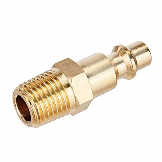

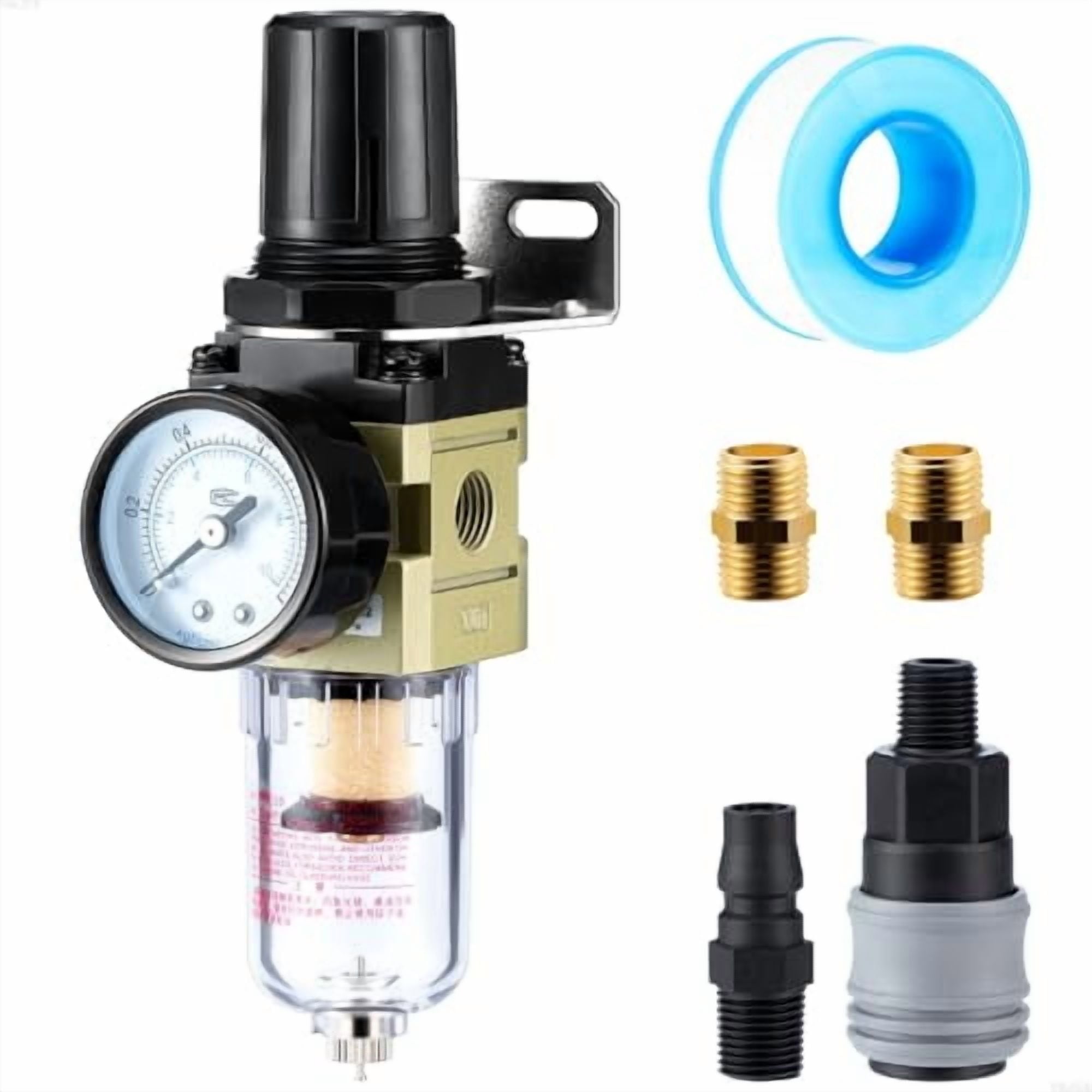
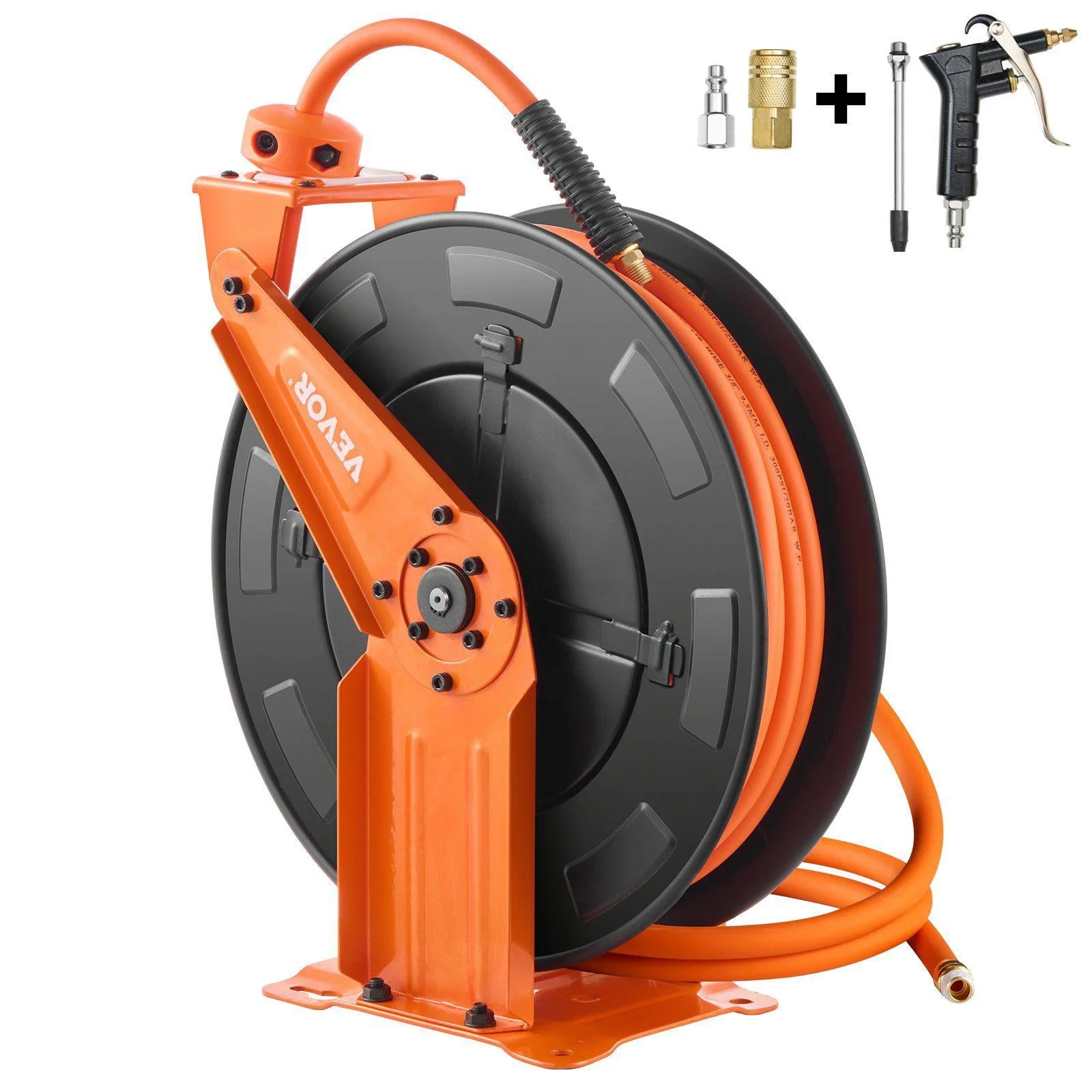
As an Amazon Associate, TestTalkHQ earns from qualifying purchases. Prices and availability can change.
A flow coefficient is not a dimension. It is a measurement. A manufacturer puts the component on a standard ISA test rig, runs water through it, and records the flow in US gallons per minute that produces exactly one psi of pressure drop. That number is the Cv. A component with a Cv of 2.0 passes twice the water of one with a Cv of 1.0 at the same drop.
The reason it exists is that a valve is not a hole. Air going through a quick coupler changes direction several times, squeezes past a ball detent, expands into a chamber and squeezes out again. No single bore measurement describes that. The Cv rolls the whole path — the dimensions, the direction changes, the internal geometry — into one number that can be compared across manufacturers and across body styles.
Water does not change density when you squeeze it. Air does. Push air through a restriction and it expands on the way out, so the mass that gets through depends on the absolute pressures on both sides, not just the difference between them. That is why every gas form of the Cv equation uses absolute pressure — psia, gauge plus about 14.7 — and why it carries an absolute temperature term as well.
The constant 22.67 is not a fudge factor. It is the published units constant for SCFM, psia and degrees Rankine, tabulated in the Swagelok MS‑06‑84 valve sizing bulletin alongside the metric equivalents, and it is the same number that falls out of the Engineering ToolBox gas equation when its SCFH form is divided by sixty.
Here is the part that surprises people who are used to thinking about water. Open the downstream side of a restriction and flow increases — up to a point. When the outlet pressure falls to half the absolute inlet pressure, the air leaves the orifice at the speed of sound. It cannot go faster. From there on, dropping the downstream pressure further buys nothing at all. You could connect it to a vacuum and the flow would not change.
MS‑06‑84 states it plainly: “Any further decrease in outlet pressure does not increase flow, even if the outlet pressure is reduced to zero. Consequently, high pressure drop flow only depends on inlet pressure and not outlet pressure.”
On 90 psig shop air the threshold sits at an outlet of about 52 psia, which is roughly 38 psig — a drop of about 52 psi. Ordinary tool feeds never get near it. Blow-off nozzles, exhaust ports and anything venting to atmosphere are choked all the time.
That last line is the one worth pinning up. The instinct is that three components sharing a drop each get an easier job. They do not. Pressure drop goes as the square of flow over Cv, so to keep the total drop the same, each of n equal components has to be √n times as large as a single component doing the whole job.
That relation is exact in the liquid equation and a good approximation for air while the total drop stays small against the absolute inlet pressure — which is the normal case for a tool feed. Near the sonic wall it stops being trustworthy, and so does any single-number answer.
Most pneumatic components sold to trades are advertised in SCFM, not Cv. That rating is meaningless on its own: it is always quoted at some pressure with some assumed drop, and the two most common headlines — 90 psig with a 5 psi drop, and 100 psig with a 10 psi drop — are not the same test.
Run the subcritical equation at the first of those and one unit of Cv passes about 22.0 SCFM at 70 °F. So:
That gives you one honest currency to compare parts in. The calculator prints the conversion on every result so a Cv answer can be taken straight to a listing that only quotes flow — and so you can spot when a listing is quoting its number at a drop nobody would accept in practice.
Cv describes discrete components: valves, couplers, plugs, regulators, filters, fittings. It does not describe a length of pipe or hose. Loss along a run is friction over a distance, a different equation with different inputs, and mixing the two is the most common way to get an air system wrong on paper. Size the distribution with the compressed air pipe size calculator and the components with this one.
It also does not tell you how much air the job needs in the first place. That comes from the tool list and the duty cycle, or from cylinder displacement if you are feeding actuators rather than hand tools.
And it assumes the component is clean and correctly installed. A filter element that has been in service for a year has a materially higher pressure drop than its datasheet Cv implies, which is exactly what the differential gauge on a good filter housing exists to tell you. Reducing bushings, adaptors and 90° street elbows screwed straight onto a coupler all add restriction that the coupler's own Cv does not include.
Cv is the flow coefficient: the number of US gallons per minute of water a component passes at one psi of pressure drop on a standard ISA test. It rolls the component's entire internal flow path — bore, direction changes, internal geometry — into a single figure that can be compared between manufacturers. For air, that same coefficient is used with a compressible-flow equation that works in absolute pressures.
While the outlet pressure is above half the absolute inlet pressure, SCFM = 22.67 × Cv × √(Δp × p2 ÷ T1), with pressures in psia and T1 in degrees Rankine. At the common catalogue headline of 90 psig with a 5 psi drop and 70 °F air, that works out to about 22.0 SCFM per unit of Cv.
It depends on what the wrench actually consumes and how much pressure you will give up, not on its drive size. A tool wanting 25 SCFM on 90 psig air with a 5 psi budget needs a Cv of about 1.14 across everything between the header and the tool — which, split across a regulator, a coupler and a plug, means each of those has to be about 1.97.
When the outlet pressure falls to half the absolute inlet pressure, air leaves the restriction at the speed of sound and the flow stops responding to further reductions in downstream pressure. From there the flow depends only on the absolute inlet pressure, the temperature and the Cv. Every component therefore has a hard flow ceiling at a given supply pressure, which this calculator reports.
No. The thread size tells you what will screw together. Published Cv for the same nominal port size varies by a factor of two or three between manufacturers and body styles — industrial-interchange, automotive-profile and high-flow couplers in the same 1/4 NPT body are three different components as far as air is concerned. Use the datasheet for the specific part number.
As the sum of the reciprocals of the squares: 1/Cv,total² = Σ(1/Cv,i²). For n identical components that means each one has to be √n times the Cv a single component would need. Three equal parts sharing a drop each need 1.73 times the assembly figure, not one third of it. The relation is exact for liquids and a good approximation for air while the total drop stays modest against the absolute inlet pressure.
Because pressure drop only exists while air is moving. A gauge on a dead-ended line reads full supply pressure; the moment flow starts, every restriction between the header and the tool begins throwing pressure away in proportion to the square of the flow. Measuring at the tool under load is the only test that means anything.
Not much. Temperature enters as a square root, so across the whole range from −40 to 212 °F the correction is roughly +12% to −11%. It is worth entering honestly for hot air straight off a compressor discharge, and it is not worth worrying about for ordinary shop air.