Contractor Job Estimator
Price remodels and GC work, then send a quote with no internal numbers.
Excel or Google Sheets. Best on a computer.
$29.00
BuyWhether the piston rod will stay straight at full extension — and the smallest rod diameter that honestly will
Price remodels and GC work, then send a quote with no internal numbers.
Excel or Google Sheets. Best on a computer.
$29.00
BuyCheckout opens here — you stay on this page.
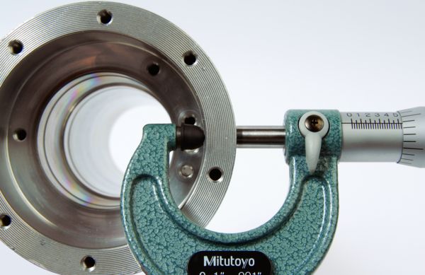
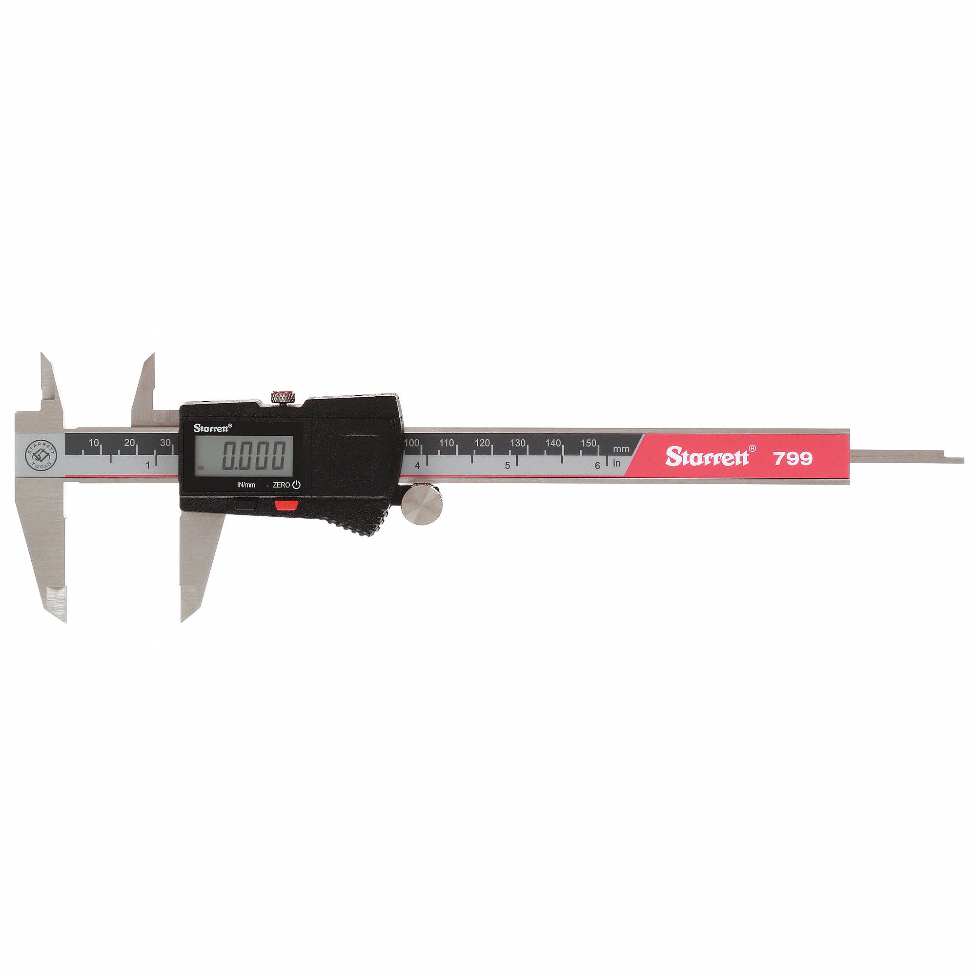
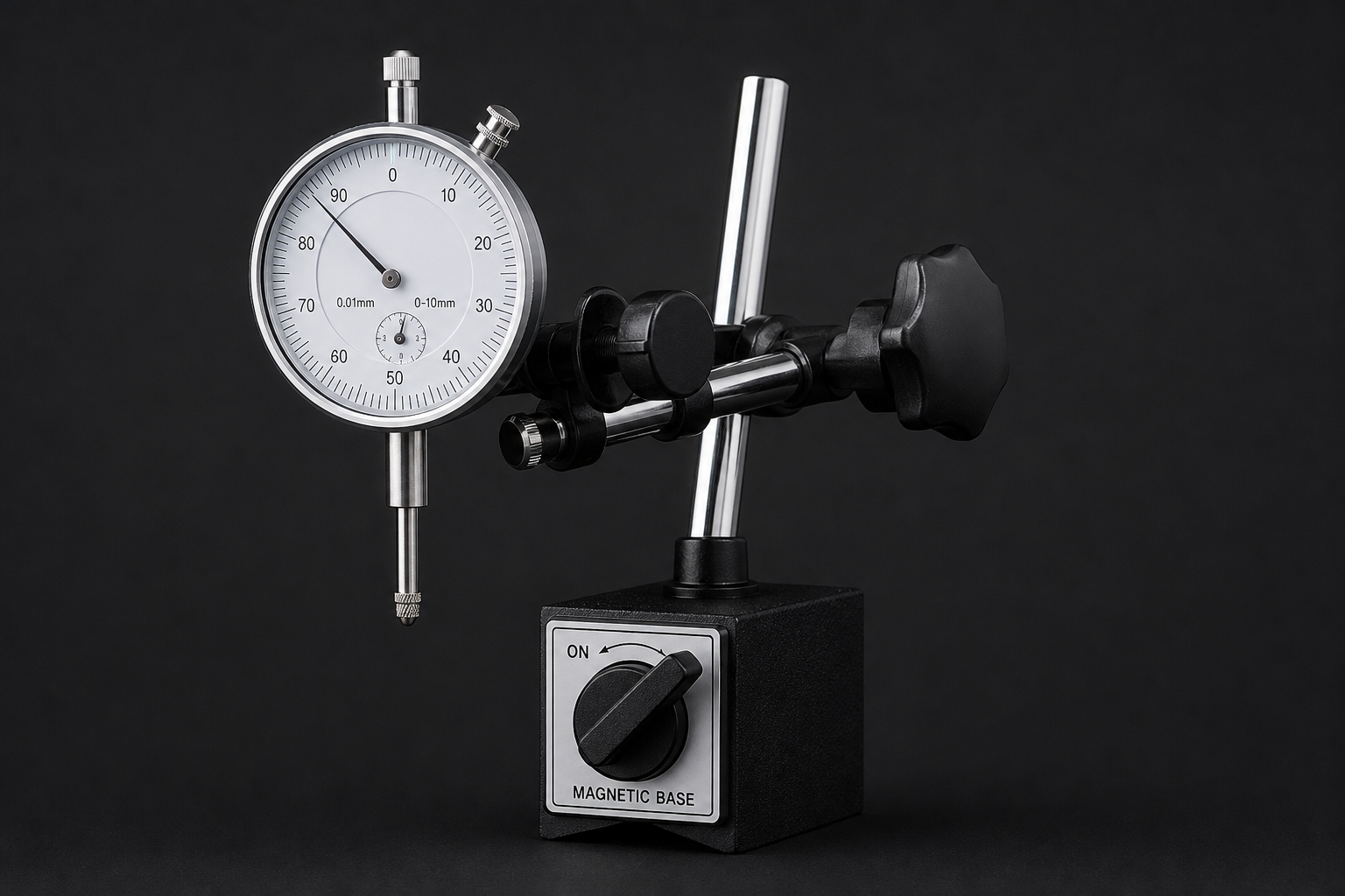
Every input above is a number somebody read off a drawing. Two of them — the rod diameter and the free span — decide the answer between them, and both are worth measuring on the machine rather than trusting to a catalogue. The third useful tool here is a regulator: pressure is the one lever you can pull on an installed cylinder without changing any hardware, and dropping it drops the buckling load in exact proportion.

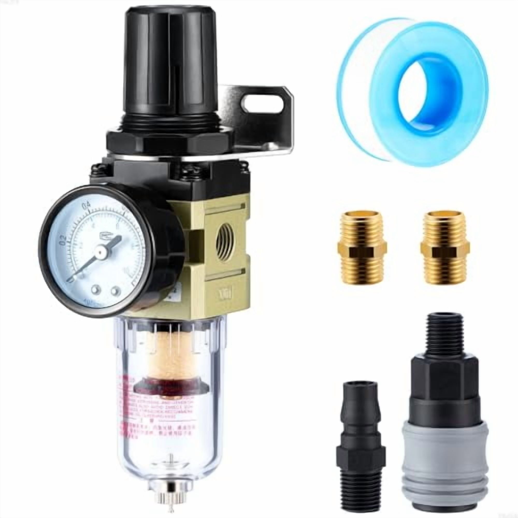
As an Amazon Associate, TestTalkHQ earns from qualifying purchases. Prices and availability can change.
Take a length of 5/8 in rod and pull on it. It will carry thousands of pounds before anything happens, because you are working the steel against its tensile strength. Now push on the same rod with the same force, with two feet of it hanging in free air. It bows sideways and folds. Nothing about the steel changed. What changed is the failure mode.
A column in compression is stable only while it is perfectly straight and perfectly loaded through its axis. It never is. There is always a thousandth of bow in the rod, a thousandth of misalignment in the clevis pin, a fraction of a degree of tilt in the mounting. Below a certain load those imperfections stay small, because the stiffness of the rod pushes it back straight faster than the load pushes it sideways. Above that load the balance tips the other way and the deflection runs away. That tipping point is the critical load, and Leonhard Euler wrote it down in 1757.
This is not a calculation the trade has to invent. Festo prints it in its technical information for pneumatic cylinders, under a buckling load graph that plots piston rod diameter against stroke and force:
Hänchen publishes the same equation for hydraulic cylinders with the mounting made explicit, as an installation factor x that multiplies the result, an elastic modulus of 210,000 N/mm², and a safety factor of 3 to 5. Bosch Rexroth works the same ground from the stress side and states the margin plainly: “the recommendation of safety against buckling of 3,5 given in the catalogue is a figure based on experience that has proven successful in the industrial use of cylinders… the selected safety factor should not be less than 2,5.”
Festo's “buckling length = 2 × stroke” is not a separate theory. It is the worst mounting case — a rigidly held cylinder body with nothing restraining the rod end — written into the length instead of into a factor. Set the mounting to that case in the calculator above and leave the extra length at zero, and you get Festo's own numbers back.
The one number in this calculation that people skip is the one that moves it most. How the cylinder body is held, and what is holding the far end of the rod, decides the shape the rod bows into — and that shape decides the load. Hänchen publishes it as a table of installation factors:
| Cylinder body | Rod end | Factor x | Equivalent K | Relative capacity |
|---|---|---|---|---|
| Rigid (flange, foot, side lug) | Free / unguided | 0.25 | 2.0 | ×1 — the baseline |
| Pivoted (clevis, trunnion) | Pivoted | 1 | 1.0 | ×4 |
| Rigid | Pivoted | 2 | 0.707 | ×8 |
| Pivoted (clevis, trunnion) | Guided in a bearing | 2 | 0.707 | ×8 |
| Rigid | Guided in a bearing | 4 | 0.5 | ×16 |
Same rod. Same stroke. Same pressure. Sixteen times the allowable load between the top row and the bottom one. That is why a cylinder that has been perfectly happy on one machine bends its rod the first week it is fitted to another.
This also points at the cheapest fix available when a rod is marginal. Adding a guide rail to the load is almost always less work than going up a bore size, and it deals with side load at the same time — which the buckling calculation does not cover at all.
Euler's equation has one flaw worth knowing about: it goes to infinity as the length goes to zero. Take a one inch length of one inch rod and it will tell you the thing carries millions of pounds. It does not — it squashes.
The standard treatment splits columns by their slenderness ratio, λ = K × L ÷ r, where r is the radius of gyration (d ÷ 4 for a solid round rod). Above a transition value, the rod buckles elastically and Euler is right. Below it, the steel starts to yield before the elastic buckling load is reached and Euler is optimistic. The transition sits where the Euler stress equals half the yield strength:
For a chrome-plated rod, λt lands around 116. A 5/8 in rod at 24 in of stroke in the worst mounting case has a slenderness of about 307 — deep in Euler territory, which is where nearly every real cylinder rod lives. The Johnson branch exists in this calculator so that a short, fat rod does not get a flattering answer, not because you are likely to need it.
A rod that passes this calculation can still end up bent, and it is worth being explicit about how.
Side load. Everything above assumes the load acts precisely along the rod axis. Anything acting across it — a load hanging off the end, a door that binds in its track, a cylinder driving a lever through an arc — puts the rod into bending, which it is far worse at than compression. Cylinder manufacturers publish side-load capacity as a completely separate figure, and that is the right place to get it. There is no general formula, because the answer depends on the gland bearing length and the rod bearing geometry of the specific series.
Stop tubes. On long strokes the usual fix is a stop tube: a spacer inside the cylinder that stops the piston reaching the very end of the tube, keeping more distance between the piston and the rod bearing and cutting the leverage the rod has on both. Bosch Rexroth names the mechanism and the rod-extension dimension that goes with it, but there is no universal formula for the length — it is a per-series table. If the calculator above says you are marginal on a long stroke, ask the manufacturer what stop tube that series wants.
End-of-stroke shock. A load arriving at speed and stopping against the cylinder is not a static thrust. Momentum can put a multiple of the rated thrust into the rod for a few milliseconds. That is what cushions and flow controls exist to absorb, and it is a different calculation with vendor-specific allowable-energy figures.
Everything that is not the rod. Rod thread, clevis, pin, gland, bearing, tube and mountings all have their own ratings. This checks one component in the chain.
A rod that is already bent. The calculation assumes a straight rod. A rod that has taken a buckling event once is permanently bowed, and it will now buckle at a much lower load than this predicts. It also ruins the gland seal and scores the bearing on the way through. Replace it; do not straighten it.
With Euler's column formula, divided by a safety factor. The permissible load is π² × E × J ÷ (K × L)² ÷ S, where J = πd⁴÷64 for a solid round rod, E is the elastic modulus (about 210,000 N/mm² for rod steel), L is the unsupported length at full extension, K is the effective length factor set by the mounting, and S is the safety factor. Festo publishes this form for pneumatic cylinders with S = 5 and the buckling length taken as twice the stroke.
It depends whose table you are following. Festo selects 5 for pneumatic cylinders. Hänchen quotes 3 to 5 for hydraulic cylinders. Bosch Rexroth recommends 3.5 as its catalogue figure and states that the selected factor should never fall below 2.5. This calculator defaults to 5, offers the others, and refuses to answer below 2.5.
No. Elastic buckling depends on stiffness, not strength, and essentially all steels share the same elastic modulus of about 210,000 N/mm². A hardened high-tensile rod buckles at the same load as a mild steel rod of identical diameter. The only material change that helps is one with a higher modulus, and for practical rod materials there is not one. Increase the diameter instead — capacity goes as the fourth power of it.
Because it decides the shape the rod bows into, and the critical load depends on the square of the effective length. A rigidly mounted cylinder with a free rod end behaves like a column twice its actual length; a rigid cylinder with the load on its own linear guide behaves like one half its actual length. That is a four-to-one range on effective length and therefore a sixteen-to-one range on allowable load, for the same rod and the same stroke.
The unsupported span between the two supports with the rod fully extended. For a bare rod that is the stroke, which is the convention the manufacturers use. Add anything that lengthens the free span: a rod extension, a long rod eye or clevis, a coupling nut, a stub projecting past a guide. Do not add the cylinder body — the tube is not part of the column.
No. Retracting puts the rod in tension, and a rod in tension cannot buckle. Buckling is only ever an extend-stroke problem, and it is worst at full extension where the unsupported length is greatest. The calculator reports the retract thrust separately so the annulus figure is there when you need it for something else.
It is the conservative default, and it is what Festo's published graph assumes: a rigidly mounted cylinder body with an unguided rod end. If your cylinder is pivoted on a clevis and the rod end is on a pin, or the load runs on its own guide, the real factor is lower and using 2 × stroke will make you buy more rod than you need. Set the mounting honestly and the calculator applies the right factor.
A spacer inside the cylinder that prevents the piston from reaching the very end of the tube, keeping a minimum distance between the piston and the rod bearing. That distance is what resists the rod tilting inside the cylinder, so a stop tube reduces the leverage a long extended rod applies to the gland and bearing. Long strokes are where they are used. There is no general formula for the length — it is published per cylinder series, so ask the manufacturer.
Replace it. A rod that has yielded in bending is permanently bowed, and the eccentricity left behind means it now buckles at a considerably lower load than a straight one. A bent rod also works the gland seal sideways every stroke and scores the rod bearing. Straightening restores the shape but not the story, and the underlying cause — too much load, too much stroke, the wrong mounting, or side load — is still there.