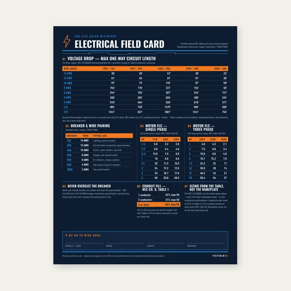
Electrical Reference Card
One page. Voltage drop lengths, breaker and wire pairing, motor FLC.
$3.99
BuyDiagnose breaker mismatches, bad interlock/backfeed installs, nuisance trips, and twist-lock plug failures — when the transfer switch calculator already looked right
Not another install walkthrough. Pair this with the Transfer Switch Calculator when amp rating and circuit count passed but the outage still fails. For manual vs automatic planning and NEC 702 context use Generator Transfer Switch Guide. Generator stalls or brownouts after transfer gear is wired are usually capacity — see Generator Sizing Troubleshooting. Tank hours are separate: Fuel Runtime Troubleshooting. This page stays on transfer equipment diagnosis.

Use this when the switch amp rating matched the generator on paper but circuits do the wrong thing, breakers trip for no obvious load reason, the interlock feels “off,” or the cord will not seat at the inlet.
| Problem | What it usually means | First fix | Next tool |
|---|---|---|---|
| Breaker positions don’t match real circuits | Wrong wire landed on labeled position; 240 V load on one pole; “furnace” switch runs kitchen | Map each MTS position to panel breaker with electrician; label after test | Transfer Switch Guide |
| Backfeed / interlock installed wrong | Main + gen can both be on; interlock plate misaligned; suicide cord temptation | Stop using it; licensed electrician re-inspect per NEC 702.6 | Transfer Switch Guide |
| Nuisance trips — switch vs generator rating | 30 A switch on 50 A gen output; peak watts used instead of continuous; gen breaker trips before switch | Size switch to generator continuous output; match cord/inlet ampacity | Transfer Switch Calc |
| Wrong plug / inlet type | L14-30 gen into L14-20 inlet; L5-30 RV plug forced; neutral/ground pin mismatch | Match NEMA config on gen, cord, and inlet — no adapters “close enough” | Transfer Switch Guide |
| Loads stall after transfer (not a switch fault) | Generator undersized or stacked circuits — transfer gear is fine | Do not upsize the switch first — diagnose capacity | Sizing Troubleshooting |
What it looks like: Install passed inspection. First outage: you flip “well pump” and the kitchen lights come on. Furnace never runs on GEN. Or a 240 V well pump only gets 120 V because one pole landed on the wrong transfer position. Calculator said 10-circuit / 30 A — the failure is wiring identity, not amp math.
Likely causes: Electrician landed feeds on the wrong MTS breaker during a long reroute. Labels assumed panel breaker numbers match transfer positions — they do not unless verified. 240 V circuits split across two slots but only one pole switched. Shared neutral issues when circuits were moved without tracing. Homeowner added loads after install without updating the circuit list.
Fixes: With utility power stable, shut off one main-panel breaker at a time and note which loads die — build a truth table. Repeat on GEN with one MTS position at a time. Correct mis-lands with the electrician; re-label every position on the MTS cover. Re-run the circuit list from the Transfer Switch Guide — essentials first, 240 V counts double. Use a Kill-A-Watt or clamp meter on each position after correction to confirm the load you think you are feeding.
What it looks like: Main breaker and generator backfeed breaker can both feel “on.” Interlock slide binds or leaves a gap where both could close. Utility power still present on branch circuits while gen is running. Inspector red-tag, or worse — neighbor’s utility line energized. DIY “suicide cord” still in the garage.
Likely causes: Interlock plate mounted on wrong breaker spacing (not listed for your panel model). Main breaker handle travel longer than interlock allows — partial engagement. Backfeed breaker oversized so interlock does not fully block main. Missing placard / wrong breaker marked “GEN.” Suicide cord used because inlet was never installed.
Fixes: Stop operating immediately. Only a licensed electrician should verify NEC 702.6 separation — simultaneous utility and generator connection is never acceptable. Replace off-brand interlocks with a UL-listed kit matched to your panel catalog number. For portable installs, a manual transfer switch with explicit LINE/GEN toggles is easier to audit than a marginal interlock. Remove suicide cords from the property — they are not a backup plan.
Interlock vs dedicated MTS? Product choice is already covered in the guide — this section is field diagnosis when the chosen hardware was installed wrong.
Open Transfer Switch GuideWhat it looks like: Generator runs extension loads fine but trips its own breaker or the switch main when transfer connects. Or switch never trips but generator breaker drops every time well pump starts — even though “30 A switch on 30 A gen” looked correct. Breakers trip at seemingly modest load.
Likely causes: Switch sized to generator receptacle amps but generator continuous rating is lower than peak marketing watts. 30 A switch fed through a 10 AWG cord limited to 30 A but inrush stacks across already-on circuits. Generator breaker trips before switch because gen internal protection is tighter. Peak/surge watts used in calculator instead of continuous — switch ampacity follows continuous current.
Fixes: Read generator nameplate: continuous watts/amps first. Match switch main, inlet, and cord to that continuous figure — the Transfer Switch Calculator uses running watts for this reason. If trips track motor start, verify capacity with Sizing Troubleshooting before upsizing switch ampacity alone. Upsizing switch without upsizing generator continuous output only hides nuisance trips behind a larger breaker — heat and cord damage risk remain.
What it looks like: Cord will not twist lock fully. Inlet accepts plug but no power — or only 120 V on one leg. Burn marks on prongs. “Adapter” gets warm. RV L5-30 plug forced into household L14-30 inlet with a cheap adapter.
Likely causes: Generator ships L14-30 (125/250 V, 30 A, 4-prong) but kit inlet is L14-20 (20 A) — physical mismatch or underrated for gen. Older 3-prong L14-30 gen into 4-prong inlet without proper neutral bond plan. L5-30 RV outlet confused with household 240 V inlet. Cord length/gauge fine but NEMA configuration wrong so hot/neutral lands on wrong blade.
Fixes: Read stamps on generator receptacle, cord ends, and inlet face — all three must match NEMA family and amp rating. Replace cord or inlet as a matched set; do not stack dubious adapters. For 30 A gen output use L14-30 (or CS6364 inlet) end-to-end; derate cord if run is long. Verify 240 V across hot legs and 120 V leg-to-neutral with a multimeter before flipping MTS to GEN. Bonding/neutral questions belong to the electrician — wrong bonding mimics “bad switch.”
| Connector | Typical use | Common mistake |
|---|---|---|
| L14-30 | Most 5–8 kW portables, 30 A 125/250 V | Feeding 20 A inlet or light-gauge cord on 30 A gen |
| L14-20 | Smaller gens, 20 A max | Used with 30 A generator — trips or melted adapter |
| L5-30 | RV 125 V 30 A — hot + neutral + ground | Adapted to house 240 V inlet — wrong voltage leg count |
| CS6364 / power inlet box | Hardwired inlet to MTS | Inlet amp rating below generator continuous amps |
Manual vs automatic transfer switch tradeoffs, interlock kit as a lower-cost alternative, circuit-count planning, and “which for your setup” already live in Generator Transfer Switch Guide (Manual vs Automatic section + interlock FAQ) and the Transfer Switch Calculator (interlock vs MTS in results). Generator kW headroom and portable vs standby class live in How to Size a Generator. Do not duplicate those forks here — open the guide when the question is product choice, return here when the chosen gear misbehaves in the field.
One page. Voltage drop lengths, breaker and wire pairing, motor FLC.
$3.99
Buy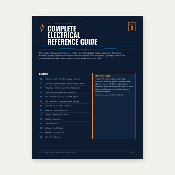
15 pages. Ampacity, corrections, voltage drop, motor circuits, conduit fill.
$12.99
Buy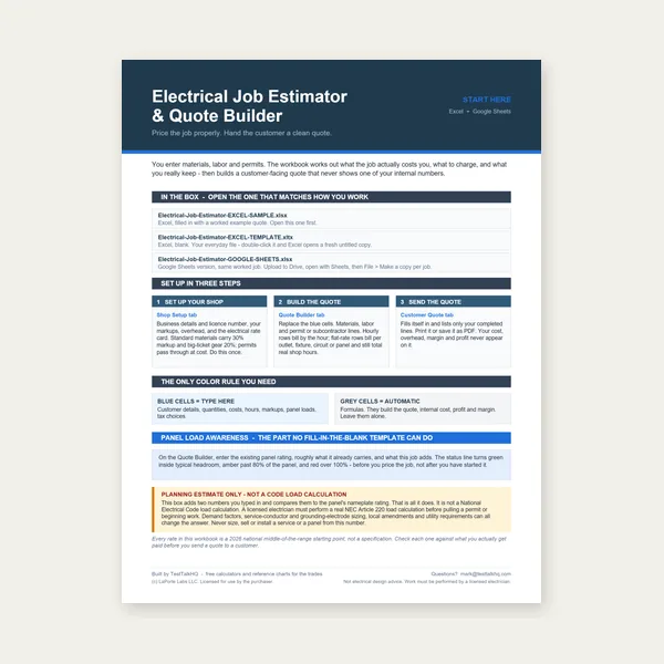
Quote electrical work and flag panel headroom before you price it.
Excel or Google Sheets. Best on a computer.
$29.00
Buy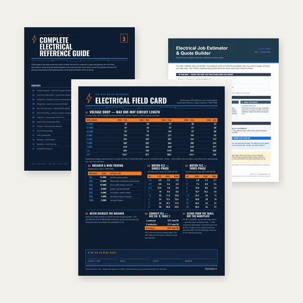
Card, 15-page guide and the estimator workbook. All six files.
Excel or Google Sheets. Best on a computer.
$34.99
$45.98 if bought separately — save $10.99
BuyCheckout opens in a new tab.
Five live CSV picks for transfer installs — kit, cord, CO safety, load verification, and voltage checks at the inlet
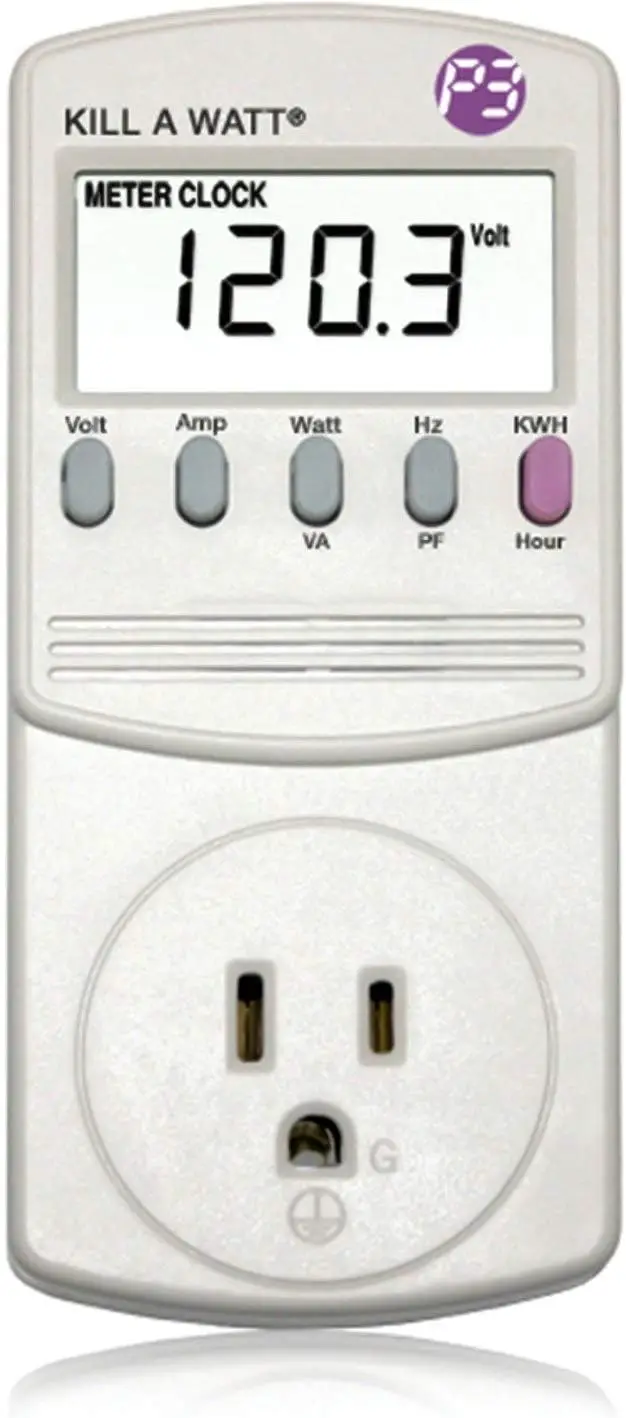

As an Amazon Associate, TestTalkHQ earns from qualifying purchases. Cards sourced from live affiliate CSV (Transfer Switches, Generator Accessories, Safety / PPE, Electrical). Catalog gaps: standalone generator inlet box (CS6364), UL-listed interlock kit matched to panel model, and twist-lock adapter sets are not in CSV — spec by NEMA, do not force-fit adapters.
Confirm continuous (not peak) generator amps, cord/inlet ampacity, and simultaneous loads. Nuisance trips are often continuous overload or motor inrush — see nuisance-trip section and Sizing Troubleshooting if starts are the trigger.
No. That is a pin-count and voltage configuration mismatch. Replace with a matched NEMA cord/inlet set.
Product choice is in the Transfer Switch Guide. This page diagnoses failures after you already chose.
Usually mis-wiring or mis-labeling. Map panel breakers to MTS positions before replacing hardware.
Often generator capacity or stacked loads. If plugs and mapping are correct, use Generator Sizing Troubleshooting.