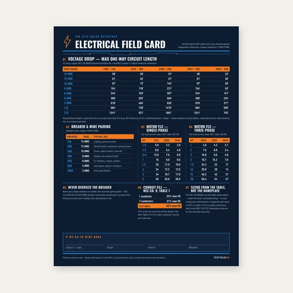
Electrical Reference Card
One page. Voltage drop lengths, breaker and wire pairing, motor FLC.
$3.99
BuyPoint-to-point method — available fault current at the transformer and at the end of a feeder run
Estimate available short-circuit current using transformer kVA, %Z, and conductor impedance over length. Compare the result against the AIC (ampere interrupting capacity) stamped on breakers, panels, and equipment at that point — NEC 110.9 requires interrupting ratings equal to or greater than available fault current. Read the Short Circuit Current Guide for AIC labels, study requirements, and upgrade scenarios.

One page. Voltage drop lengths, breaker and wire pairing, motor FLC.
$3.99
Buy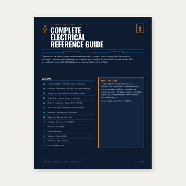
15 pages. Ampacity, corrections, voltage drop, motor circuits, conduit fill.
$12.99
Buy
Quote electrical work and flag panel headroom before you price it.
Excel or Google Sheets. Best on a computer.
$29.00
Buy
Card, 15-page guide and the estimator workbook. All six files.
Excel or Google Sheets. Best on a computer.
$34.99
$45.98 if bought separately — save $10.99
BuyCheckout opens in a new tab.
Clamp meters for high inrush checks, multimeters for dead verification, and listed panels/breakers rated for your calculated fault level.


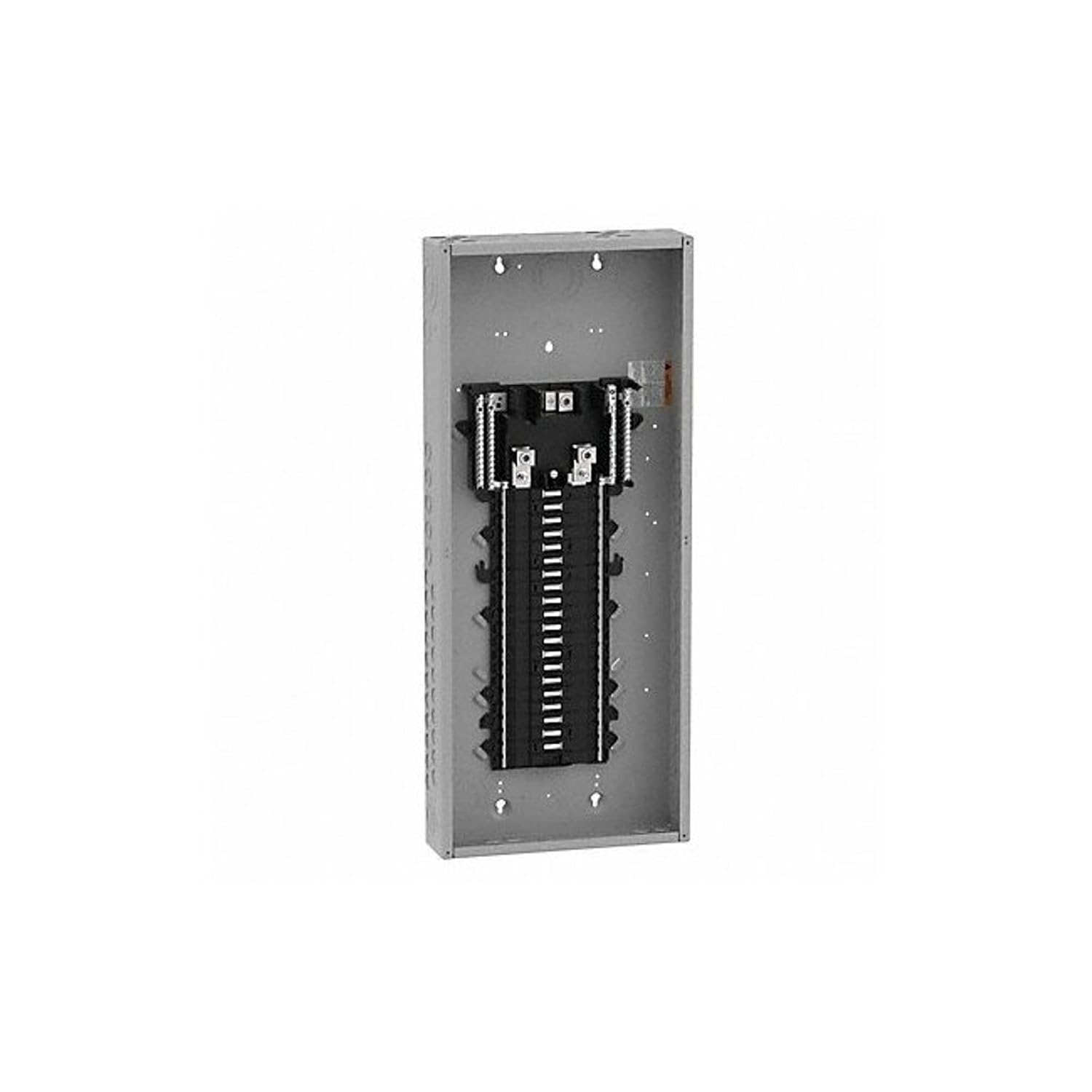

As an Amazon Associate, TestTalkHQ earns from qualifying purchases. Prices and availability subject to change.
Available fault current (also called short-circuit current or bolted-fault current) is the maximum current that can flow at a point in the electrical system during a dead short to ground or between phases. It is limited by the impedance of everything upstream — utility transformer, service conductors, transformers, and feeder runs. The value matters because every overcurrent device, panelboard, switch, and disconnect at that location must be rated to safely interrupt that current. NEC 110.9 requires equipment to have an interrupting rating at least equal to the available fault current. Underestimating fault current leads to installing breakers or panels with inadequate AIC — a condition that can cause catastrophic failure instead of clean interruption during a real fault.
This calculator uses the classic point-to-point method in two steps. First, fault current at the transformer secondary is estimated as Isc = (kVA × 1,000) ÷ (√3 × V × (%Z ÷ 100)) for three-phase transformers (line-to-line voltage in volts, nameplate %Z as a percent such as 3 for 3%). That is equivalent to the common shorthand (kVA × 100) ÷ (√3 × kV × %Z) when voltage is expressed in kilovolts. Second, conductor length adds impedance that reduces fault current downstream. The f-factor accounts for that drop: f = (1.73 × L × Isc) ÷ (C × n × V), where L is one-way length in feet, C is a conductor constant from standard short-circuit tables, n is parallel conductors per phase, and V is line-to-line voltage. The multiplier M = 1 ÷ (1 + f) is applied to get fault current at the end of the run. Longer runs, smaller wire, and fewer parallel paths all increase f and reduce available fault current at the load end.
AIC (ampere interrupting capacity), also labeled IR or interrupting rating on equipment, is stamped on the breaker toggle, the panelboard label inside the door, or the equipment nameplate. It is expressed in kAIC (thousands of amps) — a 22k AIC breaker can interrupt up to 22,000 amps. The available fault current from this calculator must be less than or equal to the equipment AIC at that voltage. Series-rated combinations are an exception but require engineering documentation and listed combinations — do not assume series rating without it. When a utility upgrades a transformer or a service entrance is enlarged, available fault current often rises; existing panels rated 10k or 18k AIC may no longer comply. Use the transformer sizing calculator for kVA and secondary current, then verify interrupting ratings before specifying equipment.
This tool produces a reasonable estimate for education and preliminary design — not a substitute for a stamped engineering study on commercial, industrial, or healthcare facilities where the authority having jurisdiction or insurance requires documented fault analysis. Software such as SKM, EasyPower, or ETAP models the full network including motor contribution, generator decrement, and X/R ratios. A rough point-to-point estimate is often sufficient for small three-phase dry-type transformer feeders when you only need to confirm a 22k-rated panel is adequate. It is not sufficient when parallel transformers, closed-transition transfers, large motor loads, or complex distribution topologies dominate the fault contribution. Licensed engineers should sign studies where the code or contract requires it.