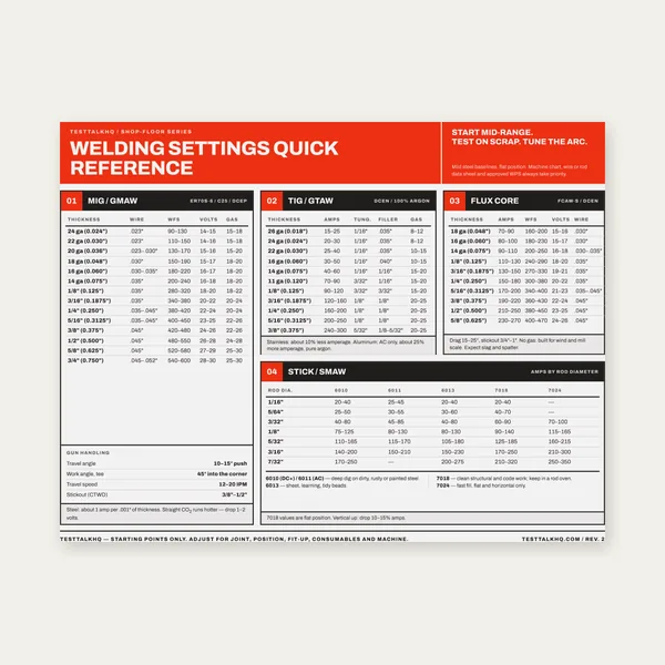
Welding Reference Card
One page. MIG, TIG, stick and flux core settings by thickness.
$3.99
BuyHow to choose the right joint type, groove detail, and weld configuration
Choosing the wrong joint type or groove detail is one of the most expensive mistakes in fabrication. It leads to poor fusion, failed inspections, excessive filler metal consumption, and rework. This guide walks through all five joint types, when to use groove welds versus fillet welds, and the AWS D1.1 groove standards that govern structural steel work. Use it alongside the Weld Joint Design Calculator to spec your joints before you strike an arc. For a plain-language overview of when D1.1 applies, see What Is AWS D1.1?.

Every weld joint falls into one of five categories based on how the base metals are positioned relative to each other. The joint type determines what weld types are available and how the joint will handle load.
Two pieces of metal joined edge to edge in the same plane. The most common structural joint. Used in pipe, plate, and structural steel wherever full strength is required. Butt joints can be square groove (thin material), V-groove, bevel, U-groove, or J-groove depending on thickness and access.
Full penetration welds, pipe welding, pressure vessels, structural connections requiring 100% joint efficiency.
Material is very thin and distortion is a concern — consider lap or edge joints instead.
One piece of metal meets another at a 90° angle, forming a T shape. Extremely common in structural fabrication, frames, brackets, and machinery. Can be welded with fillet welds (most common), bevel groove, or J-groove when full penetration is required.
Frame construction, gussets, brackets, any structural T-connection.
The joint is under high tensile load perpendicular to the weld — use a full penetration groove weld instead of a fillet.
Two pieces of metal meet at a corner, forming an L shape. Used in box sections, frames, and enclosures. Can be inside corner fillet, outside corner fillet, or open/closed corner groove welds.
Box fabrication, frames, enclosures, decorative metalwork.
The corner is under high prying or bending load — reinforce with a gusset or use a groove weld.
Two pieces of metal overlap each other and are joined by fillet welds on one or both sides. Simple to fit up, no joint prep required. Lower joint efficiency than butt joints.
Sheet metal, non-structural connections, straps, flanges, and anywhere fit-up precision is difficult.
The joint is in tension perpendicular to the weld — lap joints are weak in that direction.
Two pieces of metal are joined along their edges with both pieces in the same plane. Less common, used mainly for sheet metal and light fabrication.
Sheet metal panels, thin gauge work, non-structural joints.
Any significant load is expected — edge joints have the lowest strength of all joint types.
Fillet welds are the workhorses of fabrication. They require no joint prep — you just fit the pieces together and weld. A fillet weld's strength is determined by its throat size (0.707 × leg size) and its length. For most T-joints, corner joints, and lap joints under typical structural loads, a properly sized fillet weld is all you need. AWS D1.1 provides minimum fillet weld sizes based on base metal thickness.
Groove welds are used when full joint penetration (CJP) is required — meaning the weld fuses completely through the thickness of the base metal. CJP groove welds achieve 100% joint efficiency per AWS D1.1, making them as strong as the base metal itself. They require joint prep (beveling, grinding, or cutting the groove) and more filler metal, but they're mandatory for critical structural connections, pressure vessels, and pipe welding where weld strength must equal base metal strength.
The decision rule is straightforward: if the joint can be designed so that the calculated fillet weld size fits within the material thickness constraints and meets the load requirements, use a fillet. If the required throat size exceeds what a fillet can provide, or if the code requires CJP, use a groove weld. Always run the numbers before you cut metal — start with our Weld Joint Design Calculator.
AWS D1.1 Structural Welding Code — Steel specifies prequalified groove weld details that can be used without qualification testing. These are the most commonly used groove details in structural steel fabrication.
| Groove Type | Groove Angle | Root Opening | Root Face | Typical Application |
|---|---|---|---|---|
| Square Groove | None | Equal to t (t ≤ 3/16 in) | None | Thin plate, sheet metal |
| Single V-Groove | 60° (45–75°) | 1/4 in | 1/8 in | Plate butt joints, general structural |
| Double V-Groove | 60° each side | 0–1/8 in | 1/8 in | Heavy plate, reduces distortion vs single V |
| Single Bevel | 45° (30–60°) | 1/4 in | 1/8 in | T-joints, one-side access only |
| Double Bevel | 45° each side | 0–1/8 in | 1/8 in | Heavy T-joints, balanced heat input |
| Single U-Groove | 20° (10–30°) | 0 | 1/8 in | Heavy plate, less filler than V-groove |
| Single J-Groove | 20° | 0 | 1/8 in | T-joints requiring less distortion than bevel |
The groove angle determines welder access to the root. Too tight and you risk lack of fusion at the root — too open and you waste filler metal and increase distortion. The root opening allows the root pass to achieve full penetration. The root face (also called the land) prevents burn-through on the root pass by providing a small shelf of base metal at the bottom of the groove.
U-groove and J-groove details use less filler metal than V and bevel grooves for the same plate thickness, but they require machining or gouging to form the curved groove profile. They're common in heavy structural and pressure vessel work where weld volume is a significant cost factor.
AWS D1.1 specifies minimum fillet weld leg sizes based on the thicker base metal at the joint. These are minimums — always calculate the required throat for your load and use whichever is larger.
| Thicker Base Metal (in) | Minimum Fillet Weld Leg Size (in) |
|---|---|
| To 1/4 inclusive | 1/8 |
| Over 1/4 to 1/2 | 3/16 |
| Over 1/2 to 3/4 | 1/4 |
| Over 3/4 | 5/16 |
These minimums exist to ensure adequate heat input and fusion into the base metal. Undersized fillet welds on thick plate don't achieve proper fusion even if the visible bead looks acceptable. On the other end, there's also a maximum fillet weld size for material under 1/4 inch thick — the weld leg cannot exceed the material thickness minus 1/16 inch to avoid melting through the edge.
Joint efficiency is the ratio of weld joint strength to base metal tensile strength, expressed as a percentage. A complete joint penetration (CJP) groove weld in tension achieves 100% joint efficiency — the weld is as strong as the base metal and failure will occur in the base metal, not the weld. This is required for pressure vessels, critical structural connections, and any application where the joint must develop the full strength of the section.
Fillet welds have lower joint efficiency because their strength is limited by throat area and shear strength of the weld metal. A fillet weld loaded in shear along the weld axis (parallel shear) develops approximately 0.707 × weld leg × weld length × allowable shear stress. A fillet weld loaded in tension perpendicular to the weld axis develops higher unit strength but is still governed by throat area. For critical applications always calculate the required throat from the applied load — don't guess at leg size.
Use these companion tools to run the numbers: Weld Joint Design Calculator, Fillet Weld Strength Calculator, Groove / Butt Weld Strength Calculator, Preheat Temperature Calculator, Heat Input Calculator, and Common Weld Defects: Porosity, Undercut & Overlap.
One page. MIG, TIG, stick and flux core settings by thickness.
$3.99
Buy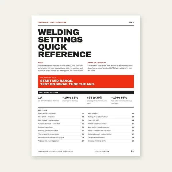
19 pages. Four processes, stainless and aluminum, symbols and inspection.
$12.99
Buy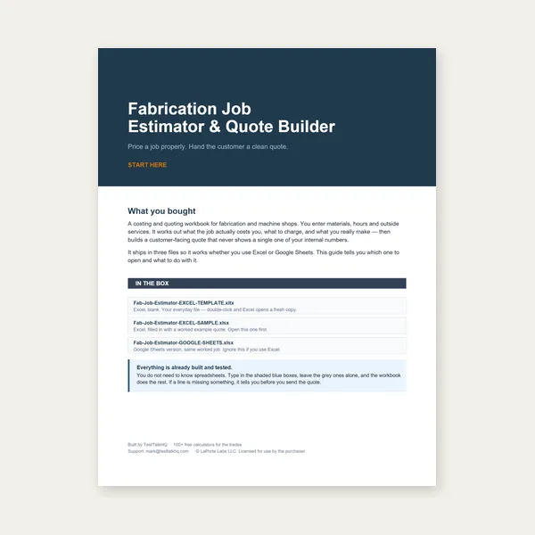
Price the job, then hand over a quote with no internal numbers.
Excel or Google Sheets. Best on a computer.
$29.00
Buy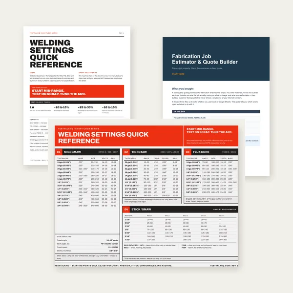
Card, 19-page guide and the estimator workbook. All six files.
Excel or Google Sheets. Best on a computer.
$34.99
$45.98 if bought separately — save $10.99
BuyCheckout opens here — you stay on this page.
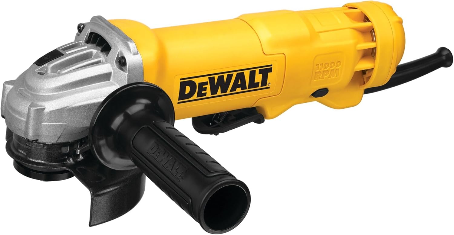
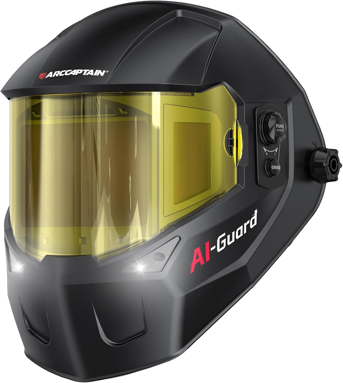
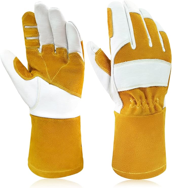
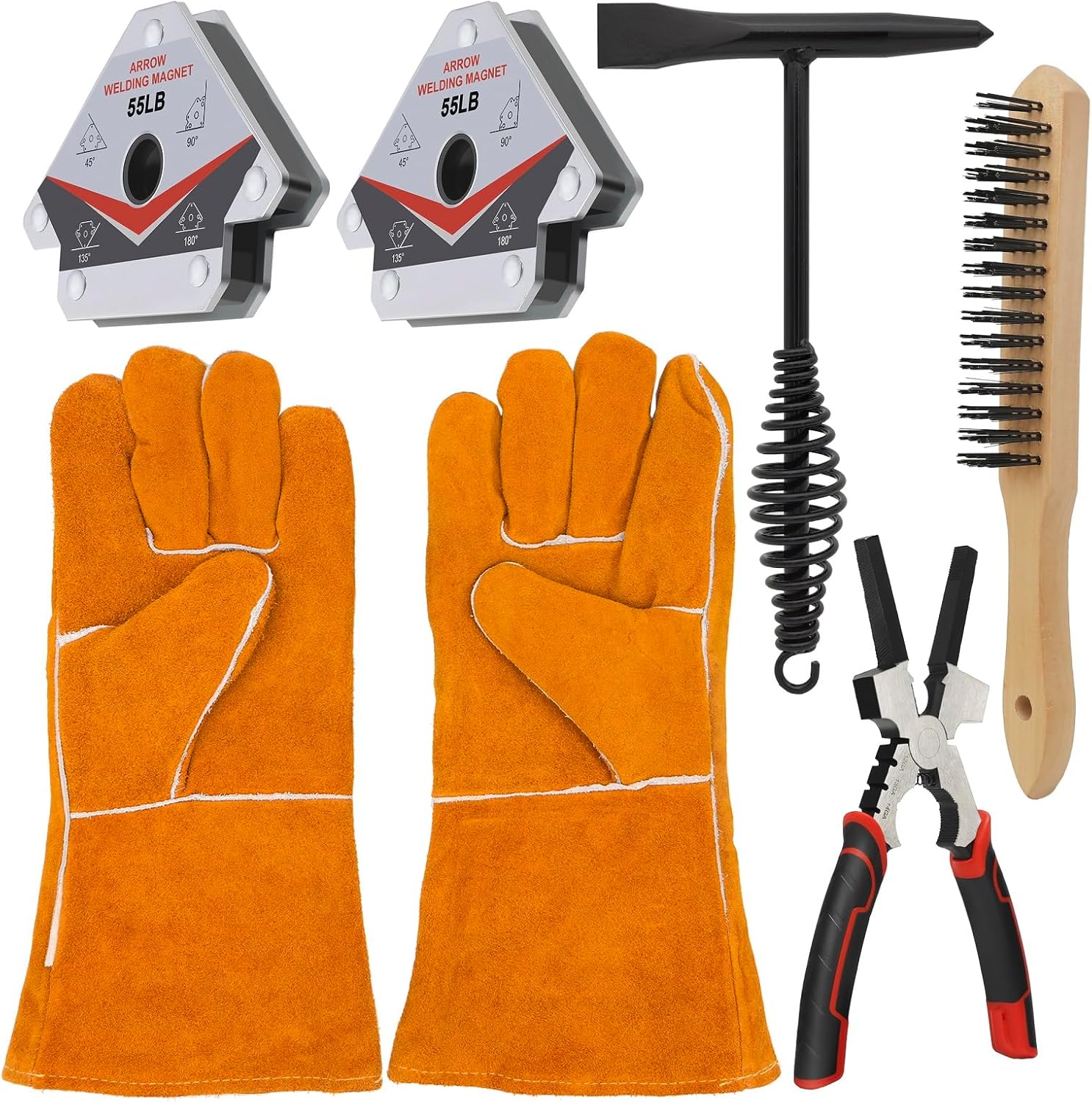
Grinders, PPE, and shop tools for groove prep, fit-up, and multi-pass welding

As an Amazon Associate, TestTalkHQ earns from qualifying purchases.
Weld symbols on engineering drawings communicate joint type, weld type, size, length, and special requirements without written notes. The reference line is horizontal, the arrow points to the joint, and symbols below the line apply to the arrow side while symbols above apply to the other side.
A tail on the reference line indicates a welding specification or process note. Learning to read weld symbols fluently is essential for any fabricator working from engineered drawings.
Joint design directly affects weld distortion. Double V and double bevel grooves distribute heat more evenly than single-sided joints, reducing angular distortion. Balanced welding sequences — alternating sides on a double-groove joint — further minimize distortion.
For thin material, lap joints and edge joints often produce less distortion than butt joints because the weld is not restrained symmetrically.
Partial joint penetration (PJP) groove welds do not fuse through the full thickness. They're used where full strength is not required and weld volume reduction is a priority. PJP welds have reduced joint efficiency and are not permitted in tension zones of critical structural members per AWS D1.1.
Always confirm whether your application requires CJP or allows PJP before selecting the groove detail.
For structural, pressure vessel, and code-governed work, joint design must be reviewed by a qualified engineer or welding engineer. The calculations in this guide and the companion calculator are for reference and education.
AWS D1.1, ASME Section IX, and API 1104 all have specific requirements for joint design, welder qualification, and procedure qualification that go beyond geometry. When lives or structural integrity depend on the weld, get the drawing stamped.
For shrinkage allowance and sequence control, see the Weld Shrinkage Calculator, Shrinkage Guide, and Weld Sequencing.
For groove capacity numbers and defect/prep companions, see the Groove Weld Strength Calculator, Strength Guide, Strength Troubleshooting, and Joint Prep Technique.
For fillet capacity numbers and defect/sizing companions, see the Fillet Weld Strength Calculator, Strength Guide, Strength Troubleshooting, and Sizing Technique.