Groove Weld Strength Guide
What determines groove weld capacity, how to read CJP vs PJP calculator output, and when grooves beat fillets on real jobs
Use this with the free Groove / Butt Weld Strength Calculator. For joint-type selection tables and AWS prequalified bevel details, see the Weld Joint Design Guide — this article focuses on strength mechanics and calculator decisions, not duplicating those tables.

What Determines Groove Weld Strength
Groove weld capacity is not a single “magic number” on a print. Four levers almost always matter together:
- Weld size / effective throat (te). For CJP butts, te is typically the full plate thickness. For PJP, te is the design effective throat (often less than thickness). Capacity scales directly with te × weld length.
- Joint prep and bevel access. Angle, land, and root opening decide whether the welder can actually achieve the throat the print assumes. A beautiful bead on a starved root is still a weak joint.
- Penetration / fusion quality. Calculators assume the detail is fused for the stated te. Incomplete fusion and incomplete penetration silently remove area from Awe.
- Base metal and filler properties. Fy / Fu of the plate and FEXX of the electrode set the allowable stress. Matching CJP in tension often becomes base-metal governed; PJP / throat shear stays filler (Fw) governed.
How to Read the Calculator Output
Open the Groove Weld Strength Calculator and walk the results in order:
- Effective throat te — CJP usually locks to plate thickness; PJP uses the throat / groove depth you enter from the detail.
- Throat area Awe = te × L — the effective weld metal area resisting the load.
- Nominal strength Rn — typically Fw × Awe for weld-metal cases (PJP / throat shear), with Fw based on FEXX.
- Design strength φRn — LRFD resistance after the strength reduction factor (commonly φ = 0.80 on PJP weld metal, φ = 0.90 when matching CJP is base-metal governed).
- Optional applied-load check — pass/fail vs your service or factored demand so you can size length or switch CJP/PJP before cutting metal.
When results look “too good,” check whether you selected CJP incorrectly on a print that only shows PJP, or whether you entered leg-size thinking from fillets. Groove capacity is throat-based, not 0.707 × leg.
CJP vs PJP — How Strength Calculations Differ
Complete joint penetration (CJP) fuses through the thickness. For a matching butt, the effective throat equals plate thickness, and tensile capacity often tracks base-metal strength when filler and procedure match code requirements. That is why CJP is specified when the joint must develop the full section.
Partial joint penetration (PJP) intentionally stops short of full thickness. Design strength uses the effective throat area and weld-metal allowable (commonly Fw = 0.60 × FEXX with φ ≈ 0.80). If you enter CJP geometry into a PJP job — or assume te equals thickness when the detail only gives partial E — you will overstate capacity.
| Type | What te usually is | What often governs | When shops specify it |
|---|---|---|---|
| CJP | Full plate thickness | Base metal (matching) or weld metal per code case | Butts needing full section strength, code CJP callouts |
| PJP | Design E / groove depth (< t) | Weld metal on effective throat | Lower demand, reduced weld volume, non-critical zones |
When Groove Welds Are Specified Over Fillets
Fillet welds win on T-joints, laps, and corners when a practical leg size meets load and AWS minimums. Groove welds win when:
- The members meet edge-to-edge (butt) and you need full plate continuity.
- Required fillet legs become huge relative to thickness — wasted filler and extra distortion for the same capacity a groove delivers with te ≈ t.
- Code or the engineer requires CJP for tension members, pressure equipment, or critical framing.
- Access and NDT plans assume a groove / butt examination path rather than fillet toes only.
Do not re-litigate that decision matrix here — the Weld Joint Design Guide and Weld Joint Design Calculator cover joint selection and prequalified prep geometry. Once the print says groove, come back here and to the strength calculator to size te, length, and FEXX against demand. For fillet capacity when that is the right joint, use the Fillet Weld Strength Calculator and Fillet Weld Strength Chart.
Turning Numbers Into Fabrication Decisions
A useful workflow on structural plate:
- Confirm CJP vs PJP and material Fy / electrode class from the WPS or print.
- Enter thickness, te, length, FEXX, load type, and φ in the calculator.
- If φRn is short, prefer longer weld, higher FEXX (when qualified), or converting PJP→CJP — not “just run hotter.”
- Lock prep so the welder can reach the assumed root (see joint prep technique).
- Plan inspection for the defects that erase calculated capacity (strength troubleshooting).
Recommended Gear for Groove Welds
Prep, consumables, and machines that support sound root passes and full design throat
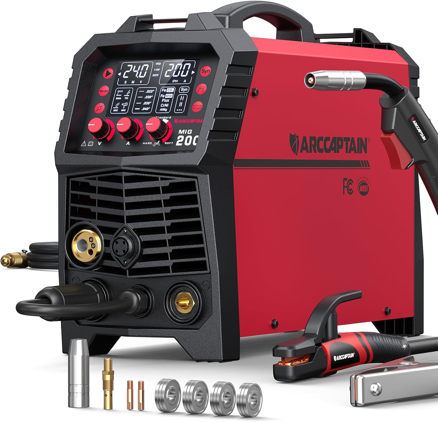
ARCCAPTAIN 6-in-1 Multi-Process
- MIG / TIG / stick for root and fill
- Stable digital meters for repeatable heat
- Dual voltage for shop or field
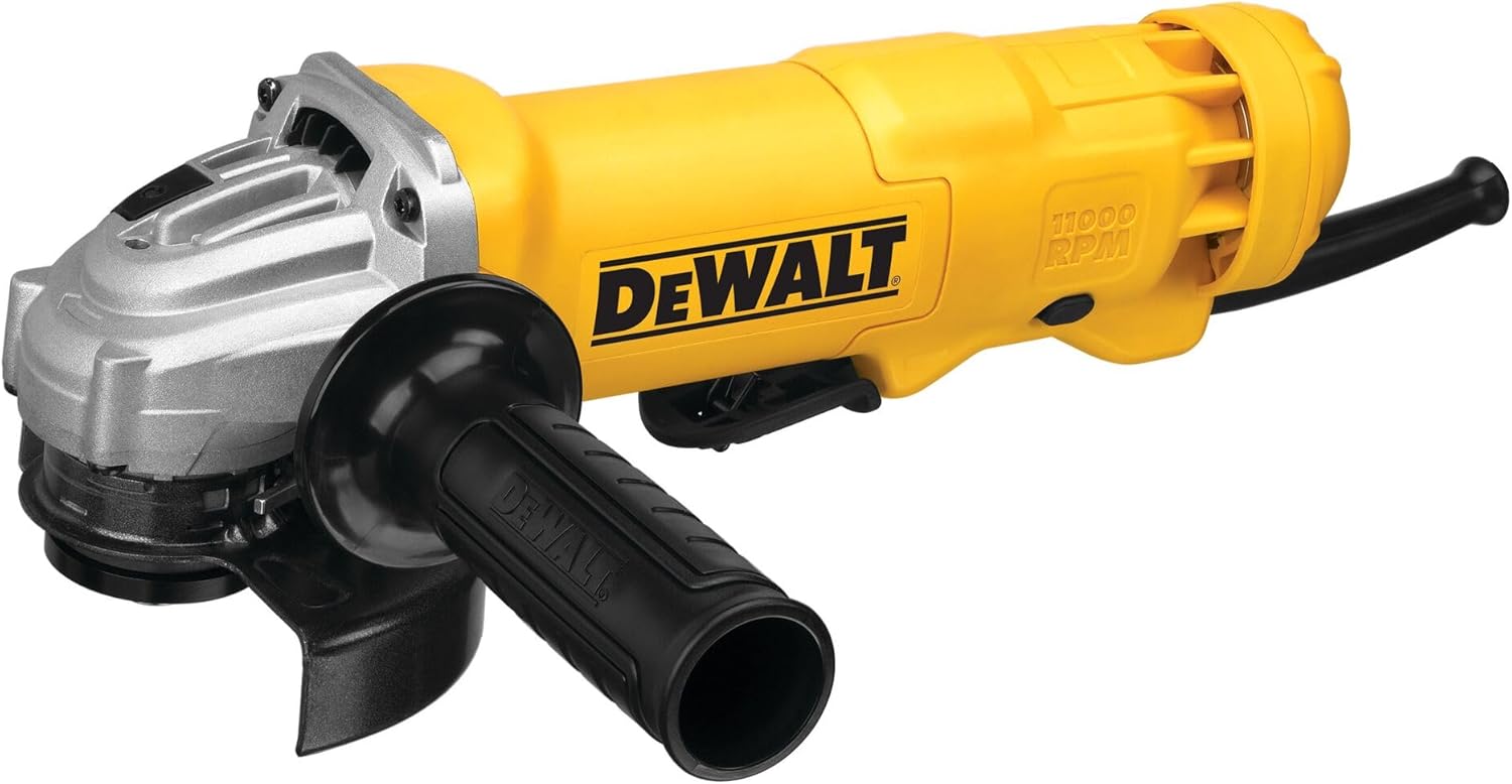
DEWALT 4.5" Angle Grinder
- Bevel edges and clean groove faces
- Open root faces without undercutting
- Essential V-groove fit-up tool
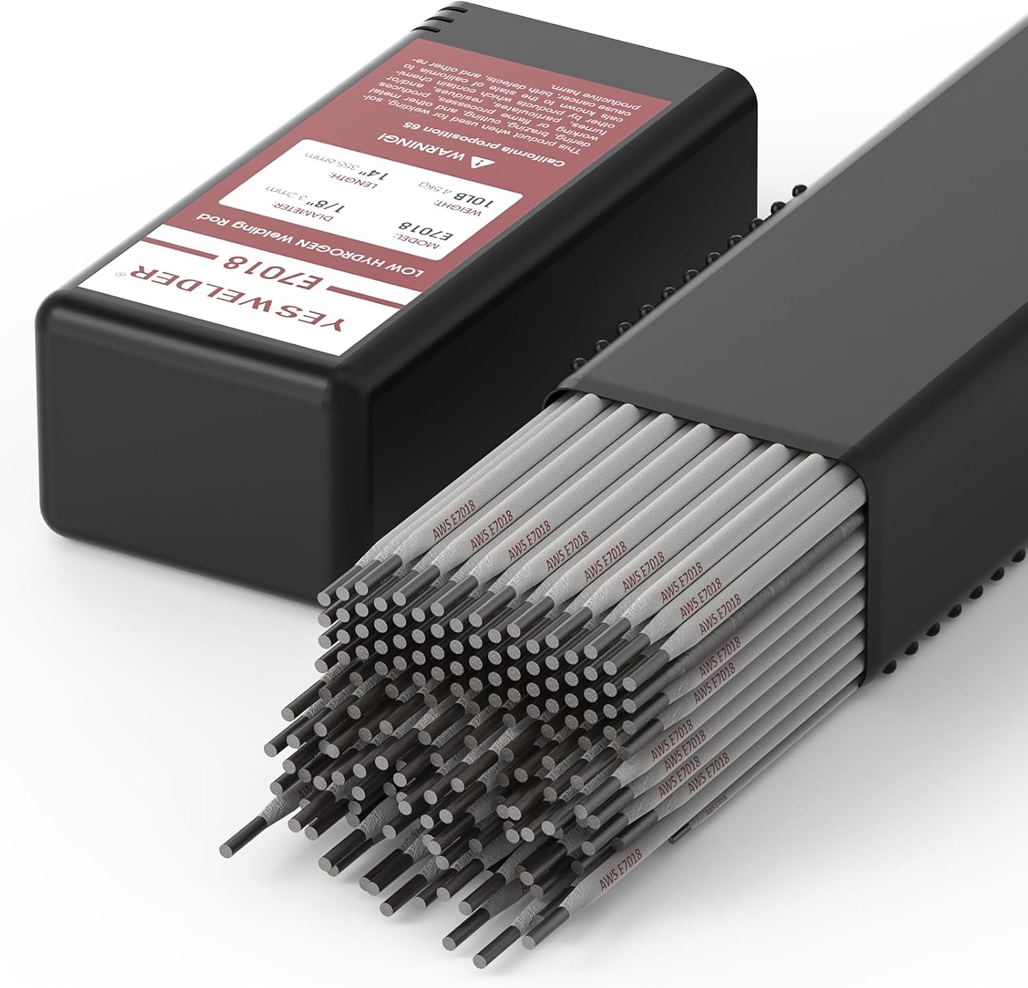
YESWELDER E7018 1/8" Stick
- E70XX class for structural grooves
- Common for CJP / PJP field work
- Keep dry for low-hydrogen soundness

VASTOOLS Welding Accessories Kit
- Chip and brush between groove passes
- Keeps slag from trapping defects
- Pairs with multi-pass root/fill work
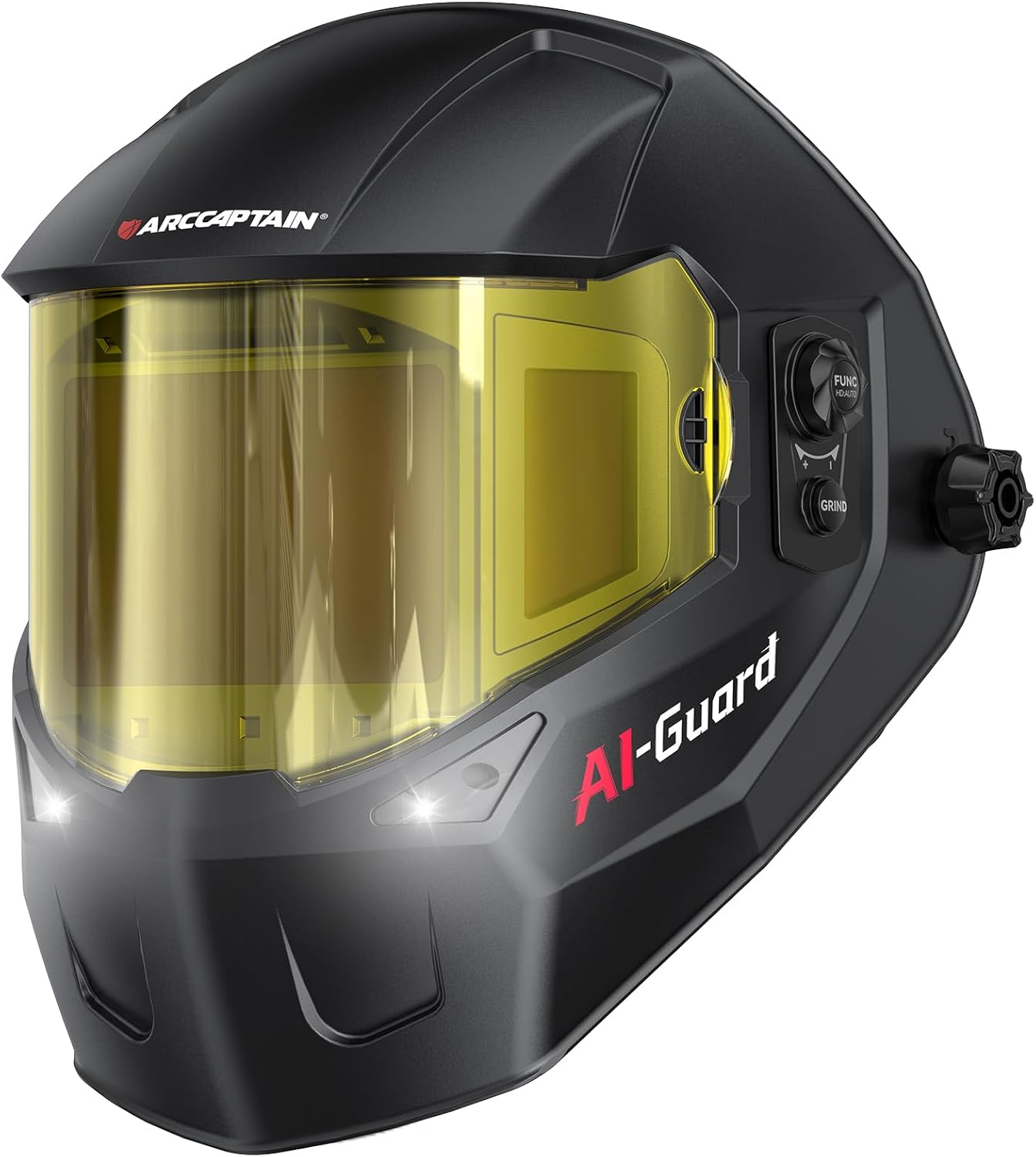
ARCCAPTAIN Halo Helmet
- Wide view for root-gap alignment
- True-color lens helps read fusion
- Comfortable for long multi-pass grooves
As an Amazon Associate, TestTalkHQ earns from qualifying purchases.
Base Metal Matching — Why φ Changes
Matching CJP in tension can be checked against base-metal strength with a higher φ (often 0.90) when filler and procedure qualify. PJP almost never gets that luxury — you are buying weld-metal throat area. Entering the wrong φ for the governing limit state is as risky as entering the wrong te.
Length, Stops, and Effective Weld Length
Calculators assume the entered length is effective. Start-stop craters, intermittents, and unwelded access windows do not count. If NDT only covers mid-span, do not pretend crater terminations develop full te.
Related Strength Defects
Calculated φRn is an upper bound for a sound weld. Incomplete fusion, incomplete penetration, toe undercut, and root porosity all reduce real area or add stress risers. Diagnose those in the troubleshooting guide; for general visual ID of porosity and undercut across processes, also see Common Weld Defects.