Fillet Weld Strength Guide
What determines fillet capacity — leg size, throat, the 0.707 factor, and effective length — and how to read the calculator for real fab decisions
Use this with the free Fillet Weld Strength Calculator and the Fillet Weld Strength Chart. For joint-type selection tables and when to switch from fillet to groove, see the Weld Joint Design Guide — this article focuses on strength mechanics and calculator decisions, not duplicating those tables.

What Determines Fillet Weld Strength
Fillet capacity is not “how pretty the bead looks.” Four levers almost always matter together:
- Leg size (a). The measured legs on the adjacent faces. Capacity scales with leg because throat grows with leg on an equal-leg fillet.
- Effective throat (t). The shortest distance from the root to the face of the diagrammatic weld. For a standard equal-leg fillet, t = 0.707 × a. This is the shear plane the calculator prices.
- The 0.707 factor. Geometry: the throat of an isosceles right triangle is the hypotenuse × √2/2 ≈ 0.707 × leg. Undersize either leg and real throat is smaller than what the print assumed for an equal-leg fillet.
- Effective length (L) and number of weld lines (n). Start-stop craters, intermittents, and unwelded corners do not count. Two-sided connections use n = 2 when both sides carry shear.
How to Read the Calculator Output
Open the Fillet Weld Strength Calculator and walk the results in order:
- Effective throat — for equal-leg fillets, 0.707 × leg. Confirm you entered the designed (or measured) leg, not face width or reinforcement height.
- Allowable weld load capacity P — weld-metal strength using Fw = 0.30 × FEXX on the throat area: P = Fw × t × L × n.
- Base metal shear rupture (φRn) — optional advanced check; governing strength is the lesser of weld metal and base metal when both apply.
- Demand / capacity — when you enter applied load F, D/C = F / Pgoverning. PASS when D/C ≤ 1.0.
- Minimum weld size (AWS D1.1) — Table 5.7 / code minimum for the thicker connected part. Size for load first, then verify the min — undersized fillets fail inspection even when “strong enough” on paper.
When results look “too good,” check whether you entered face height instead of leg, credited intermittent gaps as continuous length, or selected the wrong electrode class. For quick lb/in lookups without a load case, use the strength chart.
When Fillet Welds Are the Right Choice vs Groove Welds
Fillet welds win on T-joints, laps, and corners when a practical leg size meets load and AWS minimums with no (or light) joint prep. Groove welds win when members meet edge-to-edge (butts), code requires CJP, or required fillet legs become huge relative to thickness.
Do not re-litigate that full decision matrix here — the Weld Joint Design Guide and Weld Joint Design Calculator already cover joint selection and prequalified prep. Once the print says fillet, stay here and in the strength calculator. When the print says groove / CJP / PJP, switch to the Groove Weld Strength Guide and Groove Weld Strength Calculator — groove capacity is throat-based (te), not 0.707 × leg.
Turning Numbers Into Fabrication Decisions
A useful workflow on structural plate and light fab:
- Confirm load path, electrode class (often E70XX for A36/A992), and one- vs two-sided welds from the print / WPS.
- Enter leg, length, n, orientation, and FEXX in the calculator; add applied load for D/C.
- If D/C is short, prefer longer effective weld, a second side, or the next standard leg increment — not “just run hotter” without gauging size.
- Verify AWS minimum for the thicker part and shop maximums so the detail is inspectable.
- Gauge the as-welded legs (see sizing technique) and inspect defects that erase calculated capacity (strength troubleshooting).
Recommended Gear for Fillet Welds
Machines, consumables, and cleanup tools that support sized fillets with sound toes
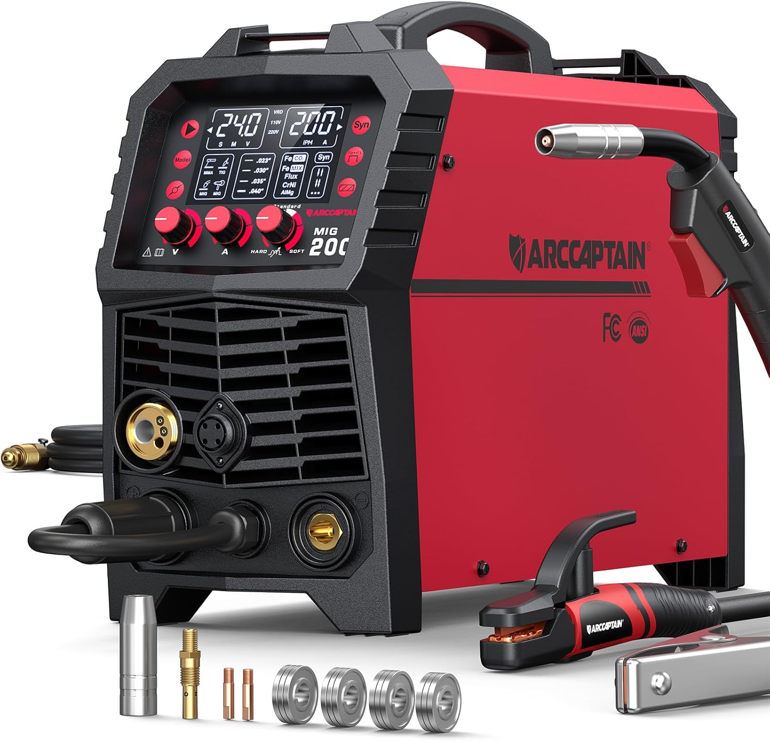
ARCCAPTAIN 6-in-1 Multi-Process
- MIG / flux-core / stick for shop fillets
- Stable digital meters for repeatable heat
- Dual voltage for shop or field
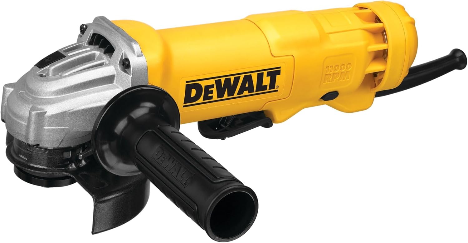
DEWALT 4.5" Angle Grinder
- Clean toes, undercut, and oversized starts
- Prep lap/T-joint edges before welding
- Essential repair tool before re-sizing
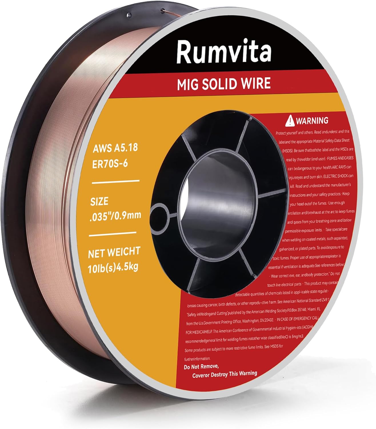
Hobart ER70S-6 .035" MIG Wire
- Matches E70XX strength class
- Common for mild-steel fillets
- Store dry for clean toes

VASTOOLS Welding Accessories Kit
- Chip and brush between fillet passes
- Keeps slag from hiding toe defects
- Pairs with multi-pass fillets
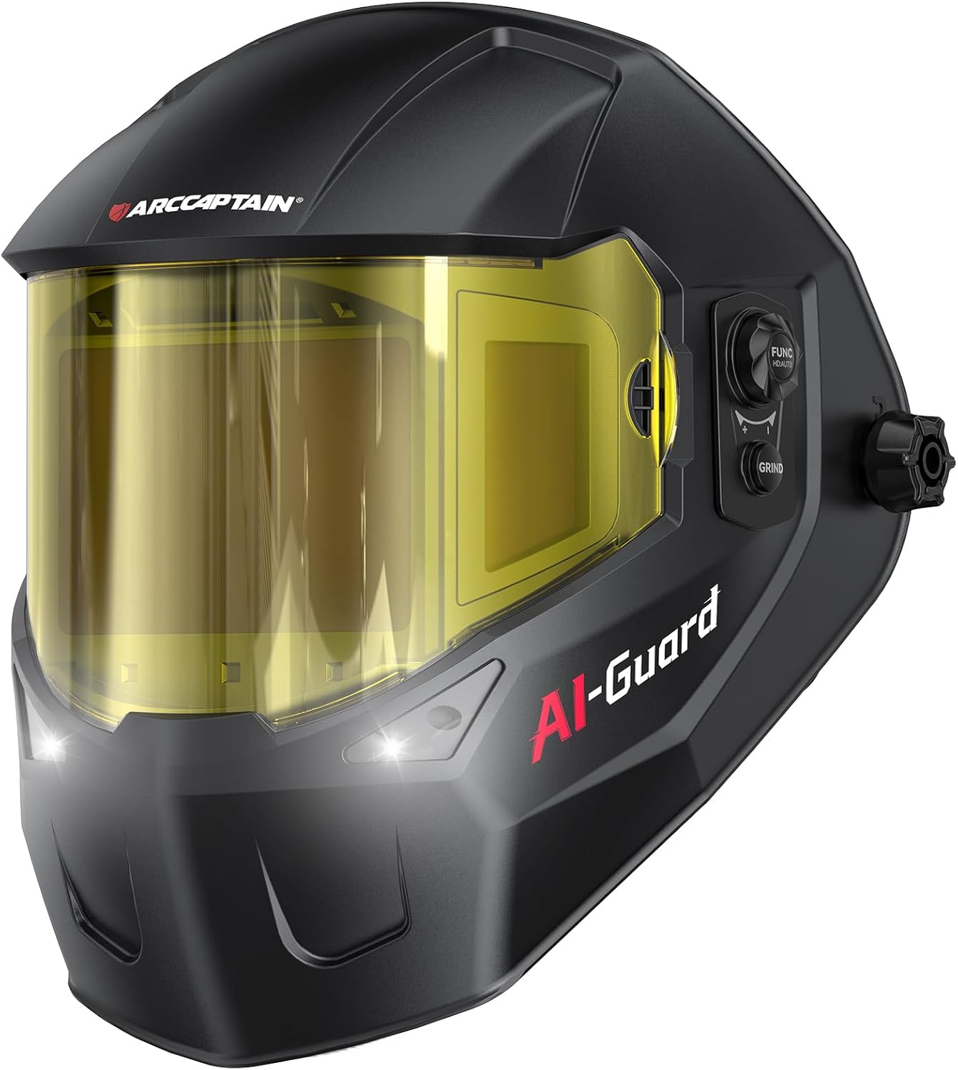
ARCCAPTAIN Halo Helmet
- Wide view for reading both fillet legs
- True-color lens helps spot undercut
- Comfortable for long intermittent runs
As an Amazon Associate, TestTalkHQ earns from qualifying purchases.
Orientation and Two-Sided Connections
Transverse fillets are common in seated connections; longitudinal (parallel) fillets appear on built-up members. Enter n = 2 when both sides carry shear. Critical connection geometry still belongs in engineer-stamped software — this calculator is a planning and shop verification tool.
Effective Length Reality Check
Calculators assume the entered length is effective. Start-stop craters, skipped corners, and intermittent gaps do not count. If the print shows 3–3 intermittent, enter total deposited length (or convert correctly) — not the full joint span.
Related Strength Defects
Calculated P is an upper bound for a sound fillet. Insufficient leg, excess convexity/concavity, overlap, toe undercut, and incomplete fusion at the root all reduce real capacity. Diagnose those in the troubleshooting guide; for general visual ID of porosity, undercut, and overlap across processes, also see Common Weld Defects.