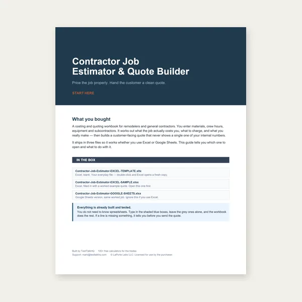
Contractor Job Estimator
Price remodels and GC work, then send a quote with no internal numbers.
Excel or Google Sheets. Best on a computer.
$29.00
BuyPan, measure, layers, delete, auto-clean, and export — all in your browser
Vendor DXF files often arrive with construction lines, duplicate segments, and layers you do not want on the laser path. The DXF Viewer, Measure & Cleanup tool loads ASCII DXF locally (nothing uploaded), lets you inspect and trim geometry, and exports a cleaned file for the Cut-Cost & Time Estimator or 2D Sheet Nesting Optimizer. For parse errors and unit surprises, see Common DXF Viewer Problems and Fixes; for whether to fix here vs in CAD, read Fix the File vs Fix the Source Drawing.
Drop a DXF, toggle off junk layers, delete strays or run Auto-clean, confirm pierce count and cut length, then export cleaned.dxf for quoting or nesting.
Open DXF Viewer →Drag a ASCII DXF onto the drop zone or click to browse. The tool parses LINE, ARC, CIRCLE, and LWPOLYLINE/POLYLINE entities with bulge support. On success you see entity count, layer list, stats panel, and the canvas. Click Fit view if the part lands off-screen.
Everything runs client-side — the file never leaves your computer. That makes it safe for customer drawings, but it also means you must export ASCII DXF from CAD (R12 recommended). Binary DXF is rejected; see the troubleshooting companion if you hit a parse error on load.
Pan is the default mode: drag the canvas to move the drawing. Wheel zoom scales around the cursor — zoom into a slot corner before deleting a stray segment. The zoom pill in the corner shows current scale; Fit view reframes all visible geometry with margin.
Use pan/zoom before you measure or delete. A full plate drawing may load tiny until you zoom; deleting the wrong line because you could not see overlap is the most common self-inflicted cleanup mistake.
Each layer appears in the left panel with a color swatch and entity count. Uncheck a layer to hide it on canvas and exclude it from readouts. Hidden layers do not add to total cut length, pierce count, bounding box, or the exported DXF.
Typical workflow: turn off DEFPOINTS, CONSTRUCTION, DIM, and any vendor centerline layers; leave the cut contour layer on. If you only need one part from a multi-part file, hide the other parts' layers rather than deleting them — faster to undo by re-checking the box.
Switch to Measure dist and click two snap points (endpoints and vertices magnetize within tolerance). The readout shows total distance, dx, and dy in the unit selected in the stats dropdown — in or mm. That dropdown relabels numbers only; it does not scale the drawing. If the file was drawn in millimeters and you display inches without converting in CAD, measurements will look wrong by 25.4×.
Measure angle needs three clicks: first leg, vertex, second leg. Use it to verify bend reliefs, tab angles, and slot orientation before export. Cross-check critical dimensions against a caliper on the physical part or drawing title block.
Delete mode: click an entity on the canvas to remove it. Hover highlights in red; only visible entities are clickable. Use Delete for one-off construction lines, crossing center marks, and duplicate contours you can see. Ctrl+Z (or the Undo button) restores the last 100 edit states.
Auto-clean runs a dedupe pass: drops zero-length segments, duplicate lines/arcs/polylines (same geometry, either direction), and degenerate circles. It does not guess which layer is "cut" vs "junk" — you still hide or delete layers intentionally. Auto-clean is fast first aid after a sloppy export; Delete is for targeted surgery.
Run Auto-clean after layer toggles, then scan the canvas once more. If duplicates were on different layers and both layers are visible, dedupe still catches identical geometry.
Price remodels and GC work, then send a quote with no internal numbers.
Excel or Google Sheets. Best on a computer.
$29.00
BuyCheckout opens here — you stay on this page.
Measure, mark, and verify cleaned DXF geometry before you quote or nest — products from the TestTalkHQ affiliate catalog.
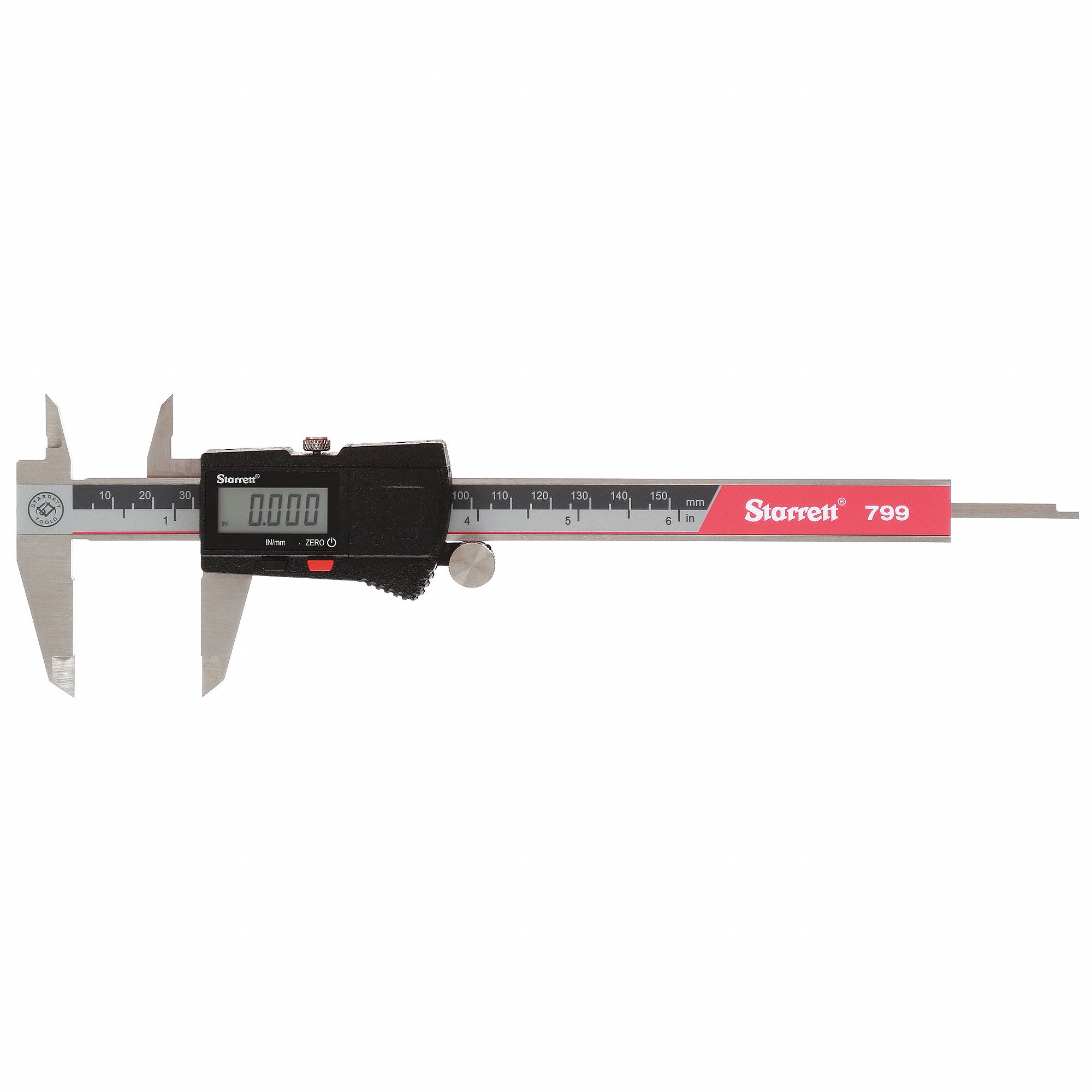
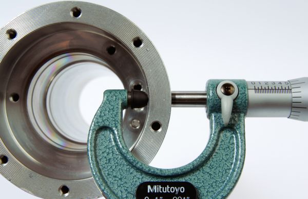
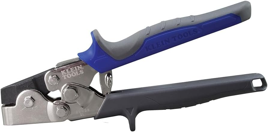
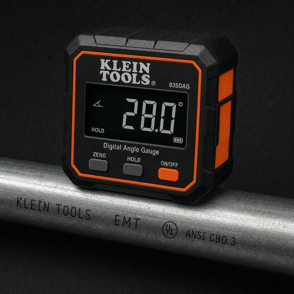
Affiliate links — we may earn a commission at no extra cost to you.
Export clean DXF writes a minimal ASCII R12-style file containing every entity on visible layers. Hidden layers are omitted entirely — not blanked, not frozen in place, left out of the file. Layer names from the original are preserved on exported entities.
Filename defaults to cleaned.dxf. Import that file into the Cut-Cost Estimator (DXF mode), the 2D Sheet Nester (per-part DXF upload), or your CAM post. Re-export if you delete more or toggle layers after the first download — there is no autosave to disk.
The stats panel updates live from visible geometry:
Pierce count drives laser/plasma lead-in time in the Cut-Cost Estimator. Cut length drives travel time. If pierces look high, look for open contours, extra loops on hidden-then-visible layers, or duplicate overlapping outlines. If length looks low, you may have hidden the real cut layer.
Cut-Cost & Time Estimator — one part profile, quoting cut time and pierce cost on a single closed or open contour set. Workflow: clean DXF → export → open Cut-Cost → DXF upload → sanity-check preview vs pierce/length readout. Good for "what does this bracket cost to laser?" before you buy plate. See DXF vs Manual Entry when CAM already gave you totals.
2D Sheet Nesting Optimizer — many parts on a sheet, kerf spacing, rotation, yield. Workflow: one part per cleaned DXF (or rectangles/circles typed manually) → upload each outline → Auto-nest. Clean here first so construction lines do not become a convex hull or extra pierces in the nest. If the nester shows convex-hull boundary, the outline still is not one closed loop — back to cleanup or CAD. See Common 2D Nesting Problems and Fixes.
Cut List Optimizer is a different problem — 1D bar and tube length nesting, not flat DXF outlines. Use it for angle and tube jobs; use this viewer for 2D plate profiles.