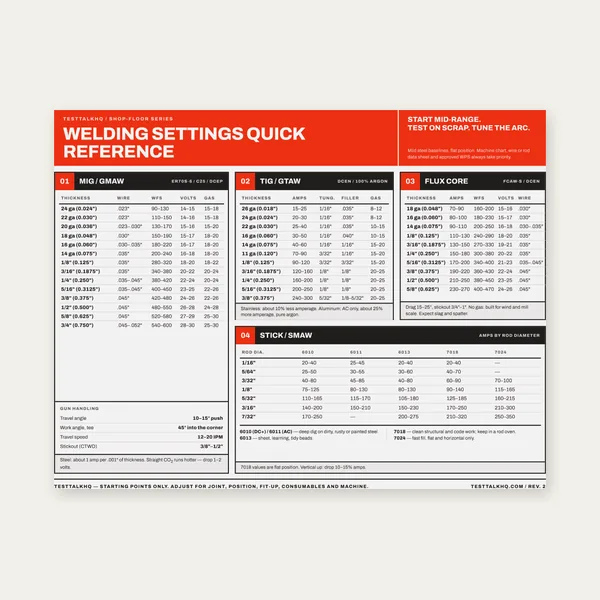
Welding Reference Card
One page. MIG, TIG, stick and flux core settings by thickness.
$3.99
BuyFix AWS A2.4 mismatches, arrow-side placement, tail notes, PNG/SVG export on drawings, and field / all-around flags
Use the live Weld Symbol Builder in Build mode to compose symbols (arrow side below the reference line, other side above) or Decode mode to read an existing symbol. Cross-check types on the Weld Symbol Reference, full chart on the Weld Symbol Chart, and test recall with the Weld Symbols Blueprint Quiz. This page covers builder-specific gaps and workflow mistakes — not general welding defect repair.

The builder supports fillet, square/V/bevel/U/J grooves, spot/plug, backing, size/count/length/pitch, groove angle/root, contour/finish, weld-all-around, field weld, tail notes (omitted when blank), and PNG/SVG export. Known chart gaps are listed in the builder disclaimer.
| Problem | What it usually means | First fix | Next tool |
|---|---|---|---|
| Symbol doesn’t match AWS A2.4 for a weld type | Unsupported symbol (flare groove, stud, edge, etc.) or known bevel/J arrow limitation | Pick a supported type; verify on chart; draw ambiguous arrow manually on print | Weld Symbol Chart |
| Weld on wrong side of reference line | Arrow-side vs other-side confusion — below = arrow side in this tool | Swap which side panel you filled; confirm arrow still points at joint | Weld Symbol Builder |
| Tail shows when you wanted none (or missing when needed) | Tail renders only when textarea has text; process notes belong in tail | Clear tail field for no tail; add WPS/process/spec text when required | Symbol Reference |
| Exported PNG/SVG wrong on drawing | Dark theme background, scale, or CAD import treats SVG as editable geometry | Export in theme that matches sheet; scale on insert; prefer PNG for Word/PDF | Builder Export |
| Field or all-around flags not as expected | Circle/flag placement vs both-side welds; flags are supplementary, not weld type | Toggle checkboxes after sides set; compare to chart example | Blueprint Quiz |
What it looks like: Your print or inspector expects flare-V, flare-bevel, stud, edge (flange), consumable insert, or melt-through notation — the builder preview cannot produce that shape. Or bevel/J-groove jobs need the arrow pointed at the prepared member and the tool always draws a straight arrow.
Supported in builder: Fillet; square, V, bevel, U, and J grooves; spot and plug; backing; contour (flush/convex/concave) with finish letters (C, G, M, R, H, P, U); weld-all-around circle; field-weld flag; tail text when non-empty. Size, count, length, pitch, groove angle, and root opening fields map to standard dimension placement for those types.
Known gaps (from builder disclaimer):
Fixes: Use the Weld Symbol Chart or Reference Tool for unsupported types. For contractual work, verify against AWS A2.4:2020 directly. Build the closest supported symbol here, then overlay handwritten or CAD-native supplementary symbols for gaps.
What it looks like: The fillet or groove appears above the reference line on the preview but the welder expected it on the arrow side (or vice versa). Decode mode reads the opposite side from what you intended.
AWS rule in this tool: The arrow points at the joint. Arrow Side controls welds below the reference line (builder panel tagged “below reference line”). Other Side controls welds above the reference line. That matches standard AWS placement when the arrow is on the left and the reference line runs through the symbol — which is how the builder draws it.
Fixes: Enter weld type, size, and dimensions in the panel that matches the physical side relative to the arrow — not “top of page” vs “bottom of page” on your monitor. If both sides get welds, fill both panels; leave a panel at “none” for single-side joints. Use Decode mode to verify which side the tool interpreted. Practice with the Blueprint Quiz arrow-side questions.
What it looks like: A tail box appears when you wanted a clean symbol with no tail — or inspectors expect a WPS / process reference in the tail and the exported symbol has none.
How the builder behaves: The tail renders only when the tail textarea is non-blank. Whitespace-only still counts as blank after trim — no tail box. Process, specification, electrode class, or “see WPS-##” notes belong in the tail per AWS when the drawing requires them; optional shop notes sometimes go in general notes instead.
Fixes: Clear the tail field completely to omit the tail (standard for simple fillet-only symbols). Add concise tail text when the drawing must carry process or spec reference on the symbol itself. In Decode mode, read tail text in the meaning panel separately from size/count on the reference line. Do not put size or pitch in the tail — those belong on the reference line fields (size, length, pitch).
What it looks like: Dark rectangle behind the symbol on a white print; symbol too small/large in CAD; SVG imports as broken paths or wrong colors; PNG looks fuzzy on large sheets.
Likely causes: Builder dark theme exports include the canvas background color — fine for dark slides, wrong on white blueprint PDFs. SVG is vector for inkscape/browser; some CAD tools rasterize poorly or ignore stroke scaling. Inserting at 100% pixel size without scaling to title-block units shrinks the symbol.
Fixes: Switch to light theme before PNG/SVG export when the destination sheet is white. Prefer PNG for Word, PDF markup, and photo overlays; use SVG when you need crisp scaling in Inkscape or web docs and will set stroke width on insert. In CAD, insert as block/image at plot scale (check title block units). Re-export after changing theme — exports capture the current canvas background and ink colors.
Need a static chart instead of a one-off export? Download or print from the chart page when the symbol type is reference-only.
Open Weld Symbol ChartWhat it looks like: You checked field weld and/or weld all around but the preview doesn’t match a chart example — circle and flag seem misplaced, or only one supplementary mark shows when you expected both.
How flags work in the builder: Weld all around adds the circle at the reference-line intersection (continuous weld around the joint outline). Field weld adds the flag at that intersection. Both can be active together — circle and flag combine per AWS layout in the tool. They do not replace weld type or side placement; you still set arrow side and other side independently.
Fixes: Set weld types and dimensions first, then toggle supplementary flags. Compare to the all-around + field examples on the chart. If the drawing needs all-around on only one side’s weld, AWS still uses one circle on the reference line — side-specific welds remain above/below the line. For quiz-style flag reading, use the Blueprint Quiz.
One page. MIG, TIG, stick and flux core settings by thickness.
$3.99
Buy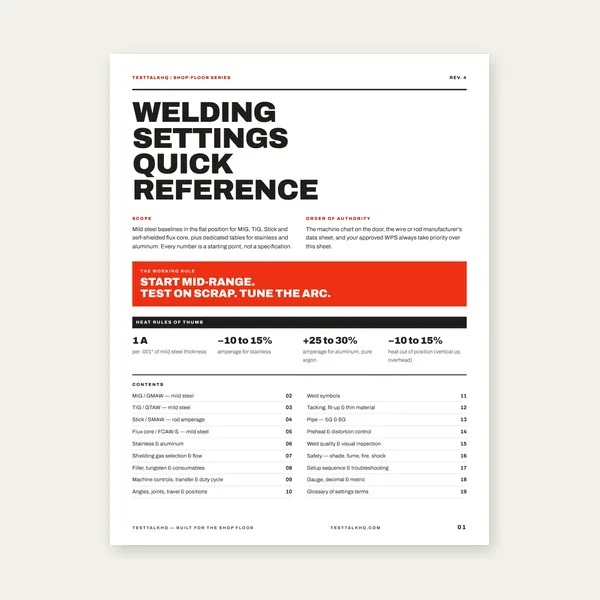
19 pages. Four processes, stainless and aluminum, symbols and inspection.
$12.99
Buy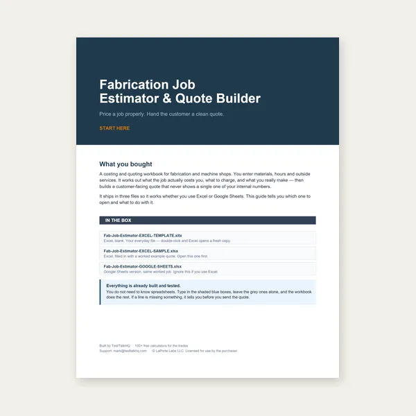
Price the job, then hand over a quote with no internal numbers.
Excel or Google Sheets. Best on a computer.
$29.00
Buy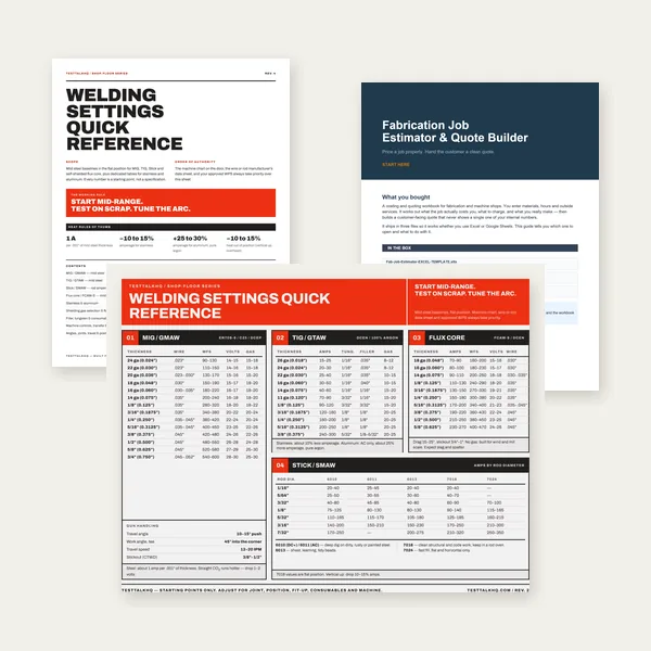
Card, 19-page guide and the estimator workbook. All six files.
Excel or Google Sheets. Best on a computer.
$34.99
$45.98 if bought separately — save $10.99
BuyCheckout opens in a new tab.
PPE and shop tools from other welding troubleshooting pages — useful when you move from symbols on screen to welds in the bay
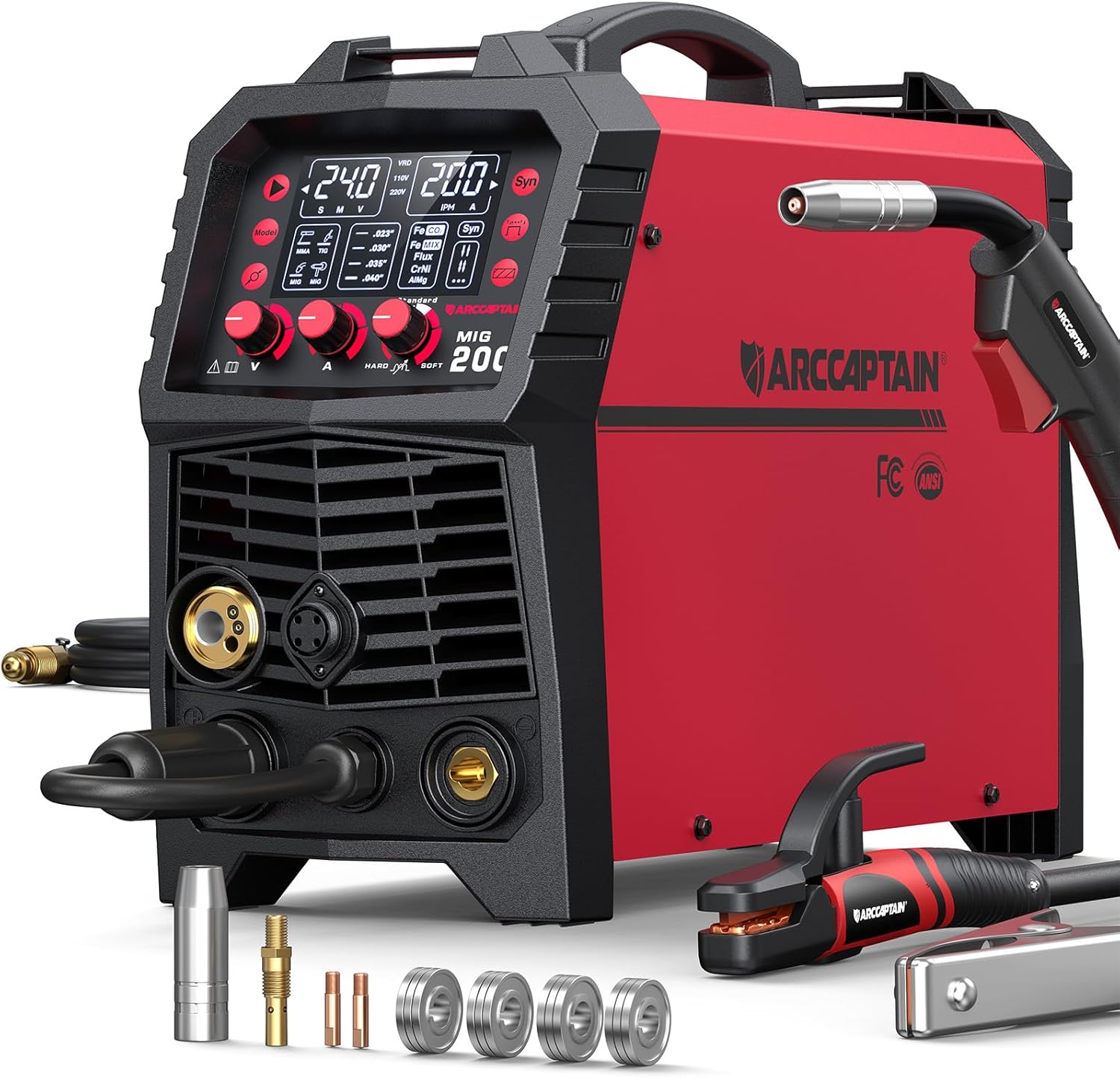

As an Amazon Associate, TestTalkHQ earns from qualifying purchases.
No. It is a study and layout aid. Known gaps are listed in the builder disclaimer — verify contractual symbols against AWS A2.4:2020 and the project drawing.
Arrow side = welds below the reference line (Arrow Side panel). Other side = above the line. The arrow points at the joint member.
The tail is omitted when the tail textarea is blank. Add process or spec text only when the drawing requires a tail reference.
Use light theme before export on white sheets. PNG is safer for PDF/Word; SVG for scalable inkscape workflows — scale on insert in CAD.
Yes — switch to Decode mode in the builder. For type-by-type lookup without composing, use the Reference Tool.
At the reference-line intersection with the arrow — circle for all-around, flag for field weld. They work together with side-specific weld symbols above and below the line.