Conduit Bending Layout Generator
Mark positions for offset, 3-point saddle, rolling offset, and segmented 90° bends
Enter the obstacle, get the exact mark distances to pencil on the conduit before you pull the handle. Big on-screen numbers for phone use at the bender, plus a printable job-site cheat sheet and a one-page multiplier reference card to tape inside your tool bag.
Where the multipliers come from
Offset multipliers are the standard trade values matching what is embossed on Klein, Ideal, and Greenlee hand-bender heads and printed in Ugly's Electrical References. They are the reciprocal of the sine of the bend angle: 1/sin(30°) = 2.0, 1/sin(45°) = 1.414 ≈ 1.4, 1/sin(60°) = 1.155 ≈ 1.2. The tool uses the rounded trade values so the numbers match the bender head — a full-precision calculator would give you 1.414 for 45°, but no bender is stamped 1.414.
| Angle | Offset multiplier | Shrinkage per unit of offset |
|---|
| 10° | 6.0 | 1/16 in per in (0.0625) |
| 22.5° | 2.6 | 3/16 in per in (0.1875) |
| 30° | 2.0 | 1/4 in per in (0.25) |
| 45° | 1.4 | 3/8 in per in (0.375) |
| 60° | 1.2 | 1/2 in per in (0.5) |
Saddle mark spacing follows the same 1/sin family applied to the side bend angle: for a 45°/22.5° saddle the center-to-side mark distance is D/sin(22.5°) ≈ 2.6·D (trade often rounds to 2.5·D); for a 60°/30° saddle it is D/sin(30°) = 2.0·D. Saddle shrinkage tracks the offset shrinkage of the side angle.
Rolling offset combines the vertical shift and horizontal shift into one true offset using the Pythagorean theorem: true_offset = √(vertical² + horizontal²). The bend angle stays whatever you pick from the standard set; the pipe just has to be rotated (rolled) so the bend plane points along the diagonal instead of straight up. The roll angle relative to vertical = arctan(horizontal / vertical).
Segmented 90° bend uses the arc-length approximation used in every IBEW and Ugly's segmented-bend example: the developed length of the finished arc is R × π/2, divided equally by the number of bends to give the mark spacing between adjacent bends. Each bend is 90° / N. This is the same lobster-back geometry used in our Cone / Transition Flat-Pattern Generator, applied here as marks along a straight conduit rather than as a cut template.
Accuracy note. These are ideal-conditions numbers. Real results vary with bender brand, deduct, conduit material (EMT vs. IMC vs. rigid), and spring-back — which depends on temperature and the pipe stiffness. Bend the first piece of a run, measure it against your layout, adjust if needed, and only then commit to a full run of bends.
Reading the on-screen marks
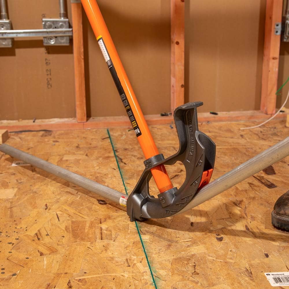
Every mark is a distance from the end of the conduit — the same way an electrician measures a stub-up. Set your tape hook on the pipe end, run out to the listed distance, and mark the pipe. Then set the bender arrow on that mark and pull the specified angle in the specified direction. Sight down the pipe before pulling the second bend of an offset or saddle to keep both bends in the same plane. If you dog-leg the pipe, cut it and start over — heating and re-bending EMT weakens the wall.
The cheat sheet PDF captures whatever layout is on screen right now — one page you can print and tape to the toolbox for this specific job. The reference card PDF is bend-type agnostic: it prints the full standard multiplier and shrinkage table plus the rolling-offset and segmented-bend formulas as a single sheet that stays useful for every job, not just this one.