Lathe Turning Speed and Feed Calculator
RPM, feed rate, depth of cut, and material removal rate for any lathe setup
Enter workpiece material, tool type, diameter, depth of cut, and operation type to get recommended SFM, spindle RPM, feed rate (IPR), surface speed, MRR, and cutting time per inch. Built for manual and CNC turning in steel, stainless, aluminum, cast iron, brass, copper, and plastic.
Also try our Milling Speed and Feed Rate Calculator, Drill Speed Calculator, and Metal Cutting Speed Calculator.

⚡ Recommended Lathe & Shop Tools
Drill sets, cutting fluid, and layout punches for turning setup and hole prep
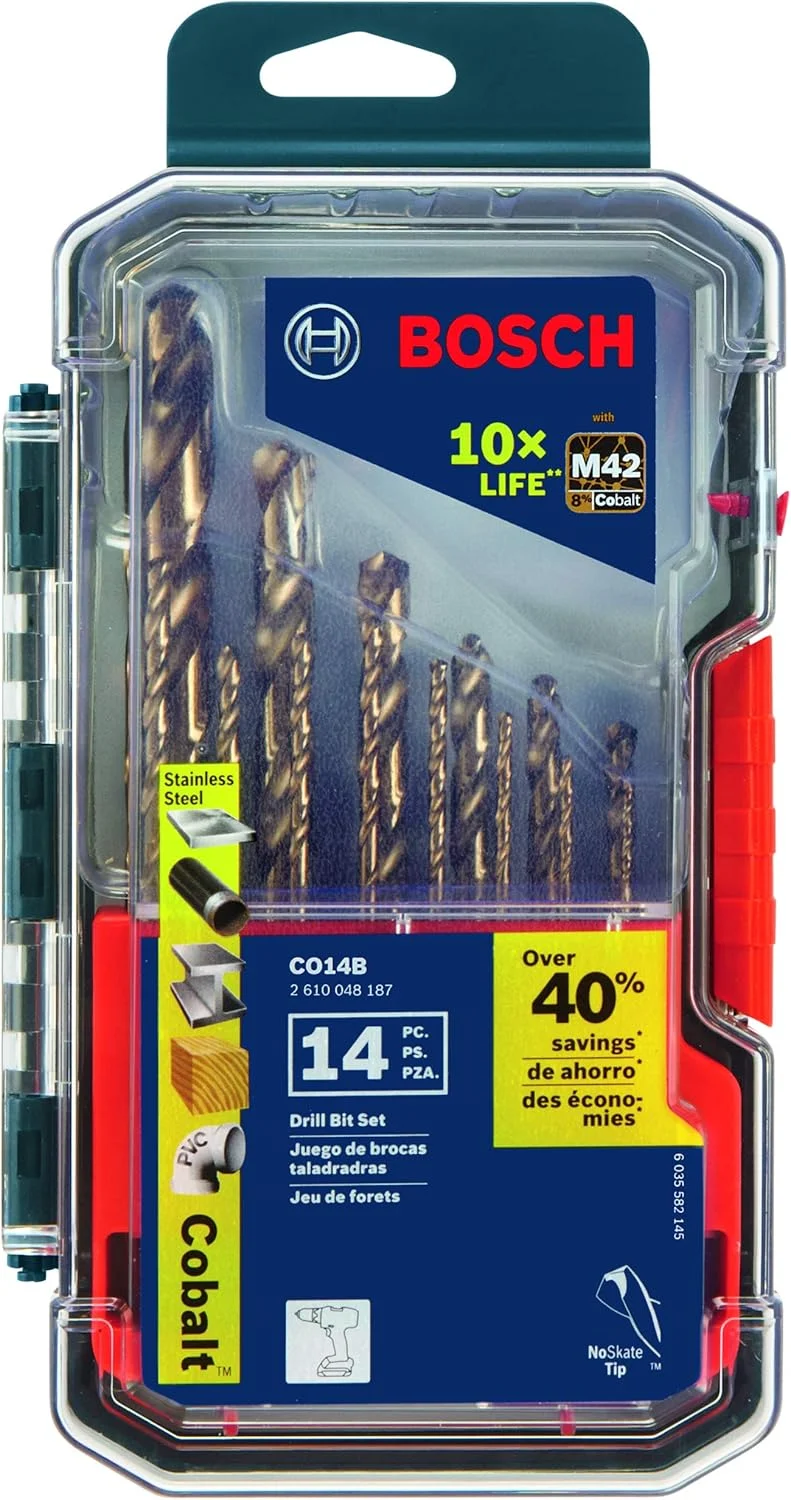
BOSCH CO14B 14-Piece Cobalt M42 Drill Bit Set
- Cobalt bits for tough alloys
- Center drill and hole prep
- Three-flat shanks reduce slip
- Wide fractional coverage
- Shop staple for metalwork

Tap Magic Cutting Fluid
- Apply at the cut zone on manual lathes
- Mandatory for stainless turning
- Reduces built-up edge on aluminum
- Extends carbide insert life
- Shop standard for machining
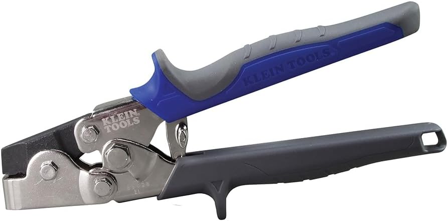
Neiko Transfer Punch Set
- Transfer hole and layout marks
- Align workpieces in the chuck
- Hardened punches for repeat use
- Essential for setup work
- Pairs with speed/feed planning
As an Amazon Associate, TestTalkHQ earns from qualifying purchases.
SFM in Turning vs Milling — Key Difference
In turning, the workpiece rotates and the tool is stationary. As the diameter decreases during a turning operation, the RPM must increase to maintain constant SFM — this is why CNC lathes use constant surface speed (CSS) mode.
On a manual lathe, you pick an RPM for the starting diameter and accept that SFM decreases as the diameter reduces. For finishing cuts on a CNC lathe, always use CSS mode for consistent surface finish across the entire face.
Roughing vs Finishing Passes — Setting Parameters
Roughing removes the bulk of material as fast as possible — high feed, high depth of cut, lower SFM to protect the tool under heavy load. Finishing achieves the final dimension and surface finish — lower feed, shallow depth of cut, higher SFM for a cleaner cut.
Never try to do both in one pass. Take roughing cuts to within 0.020–0.030 inches of final dimension, then switch to finishing parameters. Leave consistent stock for finishing — inconsistent stock causes chatter and uneven finish.
Insert Geometry and Nose Radius
Carbide insert geometry (rake angle, relief angle) and nose radius both affect surface finish and cutting forces. A larger nose radius improves surface finish but increases radial cutting force which can cause deflection on slender workpieces.
Smaller nose radius reduces cutting force and is better for finishing thin parts. For roughing, use the largest nose radius your setup can handle. For finishing, a 1/64 to 1/32 inch nose radius is typical. Always match the insert to the operation — don't rough with a finishing insert or vice versa.
Chatter in Turning — Causes and Fixes
Chatter is the self-excited vibration that causes the characteristic wavy or rippled surface finish. It's caused by the cutting force exciting a resonance in the workpiece, tool, or machine.
Common causes: workpiece sticking out too far from the chuck without a tailstock, dull insert, too high a feed rate, incorrect tool height (tool must be exactly on center), or worn spindle bearings. Fix in order: check tool height first, reduce overhang, use a tailstock, reduce feed, replace insert. Never increase SFM to stop chatter — it makes it worse.