Lathe Turning Speeds and Feeds Guide
RPM, feed rate, and SFM for every common lathe material
Wrong speeds and feeds on the lathe destroy inserts, produce poor surface finish, and scrap parts. Every material has an optimal SFM range. Every workpiece diameter converts that SFM to a specific RPM. Every operation — roughing or finishing — has a feed rate range that keeps the tool cutting efficiently. This guide gives you the numbers for every common material and tool combination with the logic to adapt when you're machining something not on the chart. Use the Lathe Turning Speed and Feed Calculator for exact numbers on your specific setup.

How Lathe Turning Speeds Work
Turning speed is controlled by SFM — the speed at which the cutting edge moves across the workpiece surface. SFM depends on the material and tool — it's the same whether the workpiece is 1 inch or 6 inches in diameter. What changes is the RPM required to achieve that SFM. A smaller diameter needs more RPM to achieve the same surface speed as a larger diameter. The formula: RPM = (SFM × 3.82) / workpiece diameter in inches.
On a CNC lathe, use Constant Surface Speed (CSS) mode — the control automatically adjusts RPM as the diameter changes during a facing cut. On a manual lathe, calculate RPM for the starting diameter and accept that surface speed drops as the part gets smaller. For finish facing, this matters — the center of the face will have a lower SFM than the outer edge, which affects surface finish.
Internal boring is a different rigidity and chip-evacuation problem than OD turning. For ID failures use Boring Bar Troubleshooting; for solid vs indexable vs head vs damped choose Boring Bar Types — Which for the Job; speeds for boring: Boring Bar Calculator.
Turning SFM by Material — Quick Reference
| Material | HSS SFM | Carbide SFM | Coated Carbide SFM | Notes |
|---|---|---|---|---|
| Mild Steel | 80–120 | 300–600 | 400–800 | Cutting oil recommended |
| Tool Steel | 40–60 | 150–300 | 200–400 | Cutting oil required |
| Stainless Steel | 40–60 | 150–250 | 200–350 | Flood coolant, low feed |
| Cast Iron | 60–80 | 200–400 | 300–500 | Dry preferred |
| Aluminum | 300–500 | 800–1500 | 1000–2000 | Flood or WD-40 |
| Brass | 200–300 | 500–800 | 600–1000 | Dry or light oil |
| Copper | 100–200 | 300–500 | 400–600 | Cutting oil, gummy |
| Plastic | 200–400 | 500–1000 | 500–1000 | Dry or air blast |
Carbide inserts run 3–5× higher SFM than HSS and are the standard for any production turning work. HSS tooling is still useful for interrupted cuts, threading, and operations where carbide's brittleness is a liability. Coated carbide (TiN, TiAlN, AlTiN) allows even higher SFM and longer tool life — the coating reduces friction and acts as a thermal barrier. For most CNC turning, use coated carbide at the upper end of the SFM range.
Ceramic inserts push SFM into territory that seems extreme — 800–1500 SFM on steel, up to 3000+ on cast iron. They're used in high-production environments with rigid machines and secure workholding. Ceramics are extremely brittle and chip instantly on interrupted cuts, hard spots, or vibration. Never use ceramic on aluminum, brass, or copper — the affinity between ceramic and these materials causes immediate built-up edge.
Mild Steel Turning — Speeds and Feeds Table
Mild steel (A36, 1018, 1020) is the most common lathe material. Carbide inserts work well across the full range of operations.
| Workpiece Dia | Carbide RPM | HSS RPM | Roughing Feed (IPR) | Finishing Feed (IPR) |
|---|---|---|---|---|
| 1/2 in | 2,293 | 764 | 0.010–0.015 | 0.003–0.005 |
| 3/4 in | 1,528 | 509 | 0.010–0.015 | 0.003–0.005 |
| 1 in | 1,146 | 382 | 0.012–0.018 | 0.004–0.006 |
| 1.5 in | 764 | 255 | 0.012–0.020 | 0.004–0.007 |
| 2 in | 573 | 191 | 0.015–0.020 | 0.005–0.008 |
| 3 in | 382 | 127 | 0.015–0.020 | 0.005–0.008 |
| 4 in | 287 | 96 | 0.015–0.025 | 0.006–0.010 |
RPM at 300 SFM carbide / 100 SFM HSS midpoint.
Stainless Steel Turning — Speeds and Feeds Table
Stainless work-hardens under the cutting tool exactly like it does under a drill bit. Keep the tool cutting — never dwell, never let the feed stop mid-cut. Use flood coolant. Take consistent chip thickness — inconsistent feed causes rubbing which work-hardens the surface ahead of the tool.
| Workpiece Dia | Carbide RPM | HSS RPM | Roughing Feed (IPR) | Finishing Feed (IPR) |
|---|---|---|---|---|
| 1/2 in | 1,528 | 382 | 0.008–0.012 | 0.002–0.004 |
| 3/4 in | 1,019 | 255 | 0.008–0.012 | 0.002–0.004 |
| 1 in | 764 | 191 | 0.008–0.015 | 0.003–0.005 |
| 1.5 in | 509 | 127 | 0.010–0.015 | 0.003–0.005 |
| 2 in | 382 | 96 | 0.010–0.015 | 0.003–0.006 |
| 3 in | 255 | 64 | 0.010–0.015 | 0.003–0.006 |
| 4 in | 191 | 48 | 0.010–0.018 | 0.004–0.006 |
RPM at 200 SFM carbide / 50 SFM HSS midpoint.
Aluminum Turning — Speeds and Feeds Table
Aluminum turns fast and rewards aggressive parameters. The risk is built-up edge — aluminum welds to the cutting tool at low speeds. Use flood coolant or WD-40, keep speeds high, and use a positive rake insert geometry for best results.
| Workpiece Dia | Carbide RPM | HSS RPM | Roughing Feed (IPR) | Finishing Feed (IPR) |
|---|---|---|---|---|
| 1/2 in | 7,640 | 2,546 | 0.015–0.025 | 0.005–0.010 |
| 3/4 in | 5,093 | 1,697 | 0.015–0.025 | 0.005–0.010 |
| 1 in | 3,820 | 1,273 | 0.015–0.030 | 0.005–0.010 |
| 1.5 in | 2,547 | 849 | 0.020–0.030 | 0.006–0.012 |
| 2 in | 1,910 | 637 | 0.020–0.030 | 0.006–0.012 |
| 3 in | 1,273 | 424 | 0.020–0.035 | 0.007–0.015 |
| 4 in | 955 | 318 | 0.020–0.035 | 0.007–0.015 |
RPM at 1000 SFM carbide / 333 SFM HSS midpoint.
Roughing vs Finishing Parameters
Roughing is about material removal rate — get stock off fast with high feed and deep cuts. Use the lower end of the SFM range to protect the insert under heavy load. Depth of cut for roughing: 0.050–0.200 inches depending on rigidity and power. Feed: 0.010–0.025 IPR for steel, higher for aluminum. Leave 0.020–0.040 inches of stock for finishing.
Finishing is about dimension and surface finish. High SFM, low feed, light depth of cut. Use a fresh or sharp insert — a worn insert that works fine for roughing will produce poor finish. Depth of cut: 0.005–0.020 inches. Feed: 0.002–0.008 IPR. Surface finish is directly controlled by the feed per revolution and the nose radius of the insert — lower feed and larger nose radius produce better finish. Ra (surface roughness) ≈ feed² / (8 × nose radius) in theoretical terms.
Depth of Cut Guidelines
| Operation | Recommended DOC | Max DOC (rigid setup) |
|---|---|---|
| Steel Roughing | 0.050–0.150 in | 0.250 in |
| Steel Finishing | 0.005–0.020 in | 0.030 in |
| Aluminum Roughing | 0.100–0.300 in | 0.500 in |
| Aluminum Finishing | 0.005–0.020 in | 0.040 in |
| Stainless Roughing | 0.040–0.120 in | 0.180 in |
| Stainless Finishing | 0.005–0.015 in | 0.025 in |
Never take a depth of cut greater than 30% of the workpiece radius on slender parts (length to diameter ratio greater than 4:1) without a steady rest or follower rest. Deflection from cutting forces causes taper and chatter. Use a live center in the tailstock for parts over 3× diameter in length.
For exact numbers on your setup, use the Lathe Turning Speed and Feed Calculator. Related tools: Milling Speed and Feed Rate Calculator, Drill Speed Calculator, and Metal Cutting Speed Calculator.
⚡ Recommended Lathe & Shop Tools
Cobalt drill sets, cutting fluid, and layout punches for lathe setup and hole prep
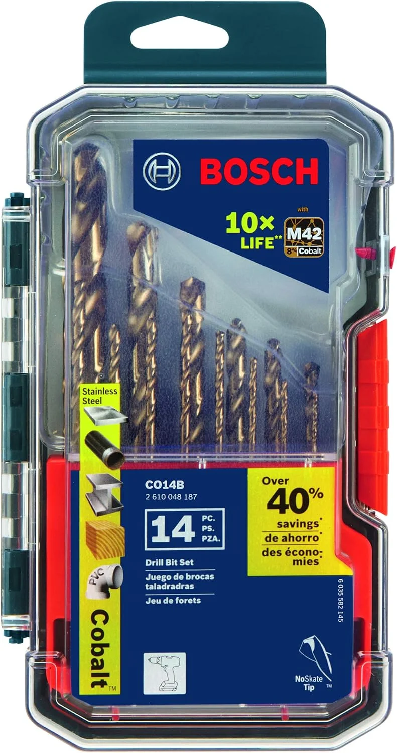
BOSCH CO14B 14-Piece Cobalt M42 Drill Bit Set
- Cobalt bits for tough alloys
- Center drill and hole prep
- Three-flat shanks reduce slip
- Wide fractional coverage
- Shop staple for metalwork

Tap Magic Cutting Fluid
- Apply at the cut zone on manual lathes
- Mandatory for stainless turning
- Reduces built-up edge on aluminum
- Extends carbide insert life
- Shop standard for machining
Neiko Transfer Punch Set
- Transfer hole and layout marks
- Align workpieces in the chuck
- Hardened punches for repeat use
- Essential for setup work
- Pairs with speed/feed planning
As an Amazon Associate, TestTalkHQ earns from qualifying purchases.
Carbide Insert Grades — What the Numbers Mean
Carbide inserts are classified by ISO grade (P, M, K, N, S, H) and ANSI designation. P grades are for steel, M for stainless and difficult materials, K for cast iron, N for non-ferrous (aluminum, copper), S for superalloys, H for hardened materials.
Within each grade, a number indicates toughness vs hardness — lower numbers are harder and more wear resistant, higher numbers are tougher and more chip resistant. For general steel turning use a P25 or P30 grade. For stainless use M20 or M25. Match the grade to the material and operation.
Tool Height in Turning — Why It Matters
The cutting tool must be exactly on center height — the centerline of the workpiece. Too high and the tool rubs on the clearance face before it cuts, generating heat and poor finish. Too low and the tool digs in, the chip geometry is wrong, and on facing operations the center won't clean up.
Check center height with a dead center in the tailstock or by facing a test piece and checking for a pip at the center. Adjust the tool post height until facing leaves no pip. This is the most common setup error on manual lathes.
Threading on the Lathe — Speed Settings
Threading requires dramatically reduced RPM compared to turning — typically 10–25% of normal turning speed for the material. The tool must engage and disengage precisely with the threading dial, and at high RPM there's no time to react.
For single-point threading in steel on a manual lathe, 50–100 RPM is typical. Use HSS threading tools or carbide threading inserts — the geometry is completely different from turning inserts. Always cut threads dry or with light oil — never use flood coolant that obscures visibility during the threading pass.
Parting Off — The Most Dangerous Lathe Operation
Parting (cutting off a finished piece) is where most lathe crashes happen. The parting blade is narrow, has minimal side support, and is highly susceptible to chatter and dig-in. Use the lowest practical RPM — typically 25–50% of turning speed.
Feed slowly and steadily — hesitation causes chatter, which causes dig-in. Keep the blade sharp. Minimize overhang from the tool post. Use cutting oil. Never part off with the tailstock engaged unless using a live center that can retract. For difficult materials, consider hacksaw parting as an alternative.