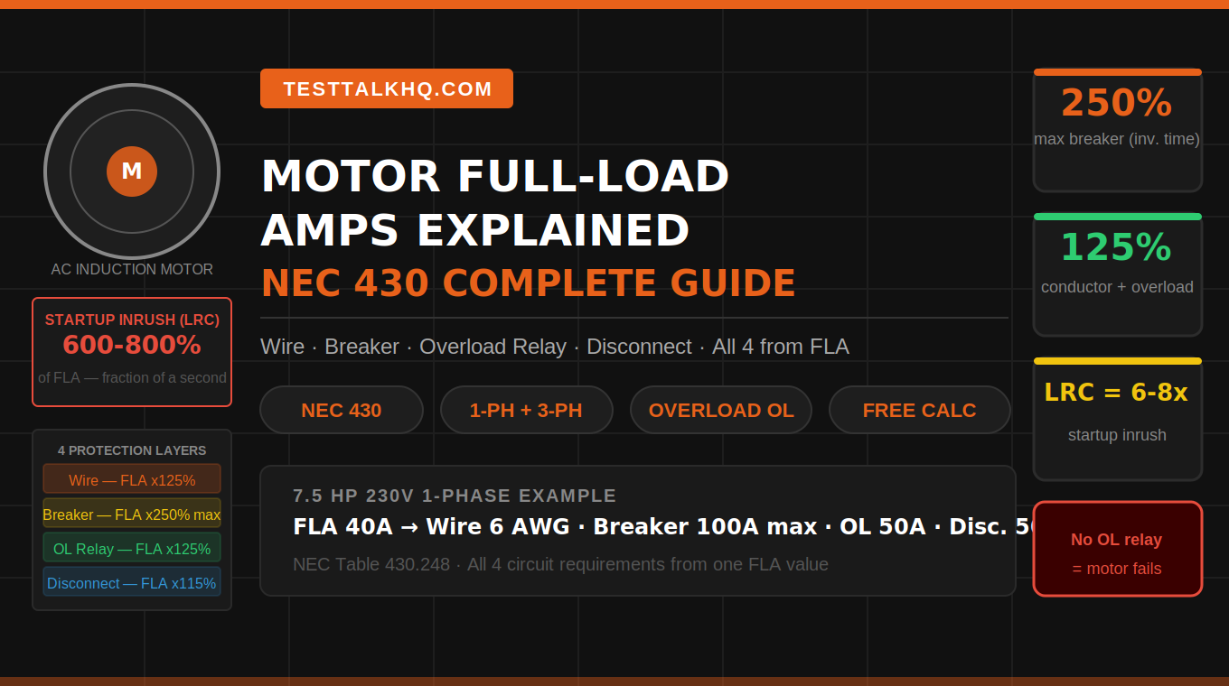
Motor Full-Load Amps Explained
How to Size Every Motor Circuit with NEC 430
Size every motor circuit from FLA per NEC 430: conductor at 125%, breaker up to 250%, overload at 125%, disconnect at 115%. Use the calculator, pre-calculated sizing chart, and FLA table below — full walkthrough follows.
Reading the NEC Motor FLA Tables
NEC Tables 430.248 (single-phase) and 430.250 (three-phase) list FLA values for standard AC induction motors at common voltages. These are used for circuit sizing calculations when the motor nameplate FLA is unavailable, and always for branch circuit protection sizing per NEC 430.6(A) — even when you have the nameplate.
📋 NEC Tables 430.248 & 430.250 — Motor FLA Quick Reference
| HP | 1φ 115V | 1φ 230V | 3φ 230V | 3φ 460V | Min Wire (460V 3φ) | Max Breaker (460V) |
|---|---|---|---|---|---|---|
| 1/2 HP | 9.8A | 4.9A | 2.2A | 1.1A | 14 AWG | 15A |
| 3/4 HP | 13.8A | 6.9A | 3.2A | 1.6A | 14 AWG | 15A |
| 1 HP | 16A | 8A | 4.2A | 2.1A | 14 AWG | 15A |
| 2 HP | 24A | 12A | 6.8A | 3.4A | 14 AWG | 15A |
| 3 HP | — | 17A | 9.6A | 4.8A | 14 AWG | 15A |
| 5 HP | — | 28A | 15.2A | 7.6A | 14 AWG | 20A |
| 7.5 HP | — | 40A | 22A | 11A | 14 AWG | 30A |
| 10 HP | — | 50A | 28A | 14A | 12 AWG | 35A |
| 15 HP | — | — | 42A | 21A | 12 AWG | 60A |
| 20 HP | — | — | 54A | 27A | 10 AWG | 70A |
| 25 HP | — | — | 68A | 34A | 8 AWG | 90A |
| 30 HP | — | — | 80A | 40A | 8 AWG | 100A |
| 50 HP | — | — | 130A | 65A | 4 AWG | 175A |
Per NEC 430.6(A): use the NEC table FLA for branch circuit protection sizing (the breaker), regardless of what the nameplate says. For conductor sizing and overload relay setting, use the higher of the table value or nameplate FLA. This means a premium efficiency motor with a lower nameplate FLA than the table value gets tighter overload protection — which is good for motor longevity — while still getting a breaker sized to handle the worst-case inrush.
All Four Calculations in One Shot
Our free motor FLA calculator gives you conductor size, maximum breaker, overload relay setting, and minimum disconnect — all from one HP and voltage entry. Covers single-phase and three-phase, all standard voltages.
The Four Components of Every Motor Circuit
NEC Article 430 treats motor circuit protection as four distinct elements, each with its own code section and sizing method. They all start from the same FLA value but use different multipliers for different reasons.
🔧 The Four Motor Circuit Protection Elements — All Sized from FLA
Need the numbers, not the lecture?
Our free motor FLA calculator gives you conductor size, maximum breaker, overload relay setting, and minimum disconnect — all from one HP and voltage entry. Covers single-phase and three-phase, all standard voltages.
You install a 5 HP compressor motor, size the breaker at 125% of FLA like you would a standard load, and it trips every time the motor starts. So you put in a bigger breaker. Now you have a code violation. Motor circuits look like standard branch circuits but they play by completely different rules — four separate protection elements all sized from the same FLA number, each with its own NEC section and multiplier. Here’s exactly how to get all four right.
What Full-Load Amps (FLA) Actually Is
Full-Load Amps (FLA) is the current a motor draws when operating at its nameplate rated horsepower under rated voltage conditions. It’s the baseline number that every motor circuit calculation starts from — conductor size, breaker size, overload relay setting, and disconnect rating all derive from FLA.
The NEC provides FLA values in two tables. NEC Table 430.248 covers single-phase AC motors. NEC Table 430.250 covers three-phase AC motors. These values are used when the motor nameplate is unavailable, and as the basis for branch circuit protection sizing per NEC 430.6(A).
Here’s what makes motor circuits different from everything else in the NEC: a motor doesn’t just draw its FLA. At the moment of startup, before the rotor is moving, the motor presents itself to the circuit as essentially a short circuit. That initial draw — called Locked Rotor Current (LRC) — is typically 600–800% of FLA and lasts for a fraction of a second until the rotor accelerates to running speed. Every piece of motor circuit design accounts for this inrush.
⚡ Motor Current Profile — Startup Inrush vs. Running FLA
Worked Example — 7.5 HP Single-Phase 230V Motor
A 7.5 HP single-phase 230V motor — the kind you see on large air compressors, woodworking machinery, and shop equipment. Let’s size the entire circuit step by step.
📒 Worked Example — 7.5 HP Single-Phase 230V Motor (NEC Table 430.248)
Notice something: the branch circuit wire (6 AWG, 65A ampacity) is protected by a 100A breaker. That seems backwards — a 100A breaker on 65A wire. This is intentional and explicitly permitted under NEC 240.4(G), which defers motor conductor protection to NEC Article 430. The oversized breaker handles inrush. The overload relay at 50A protects the motor. The wire is protected by the fact that the motor’s overload relay will trip before the wire reaches its thermal limit under sustained overload conditions.
Omitting the motor overload relay and relying on the branch circuit breaker for motor protection. Because the breaker is intentionally sized at 250% of FLA to survive inrush, it will allow a sustained overload at 150%, 200%, even 249% of FLA to flow continuously through the motor windings. The motor overheats, the insulation degrades, and eventually the motor fails. The breaker never trips. This is not a code technicality — it’s the mechanism behind most premature motor failures in the field.
Service Factor — What It Means for Overload Sizing
Service factor (SF) is a multiplier printed on the motor nameplate that indicates how much above rated horsepower the motor can operate continuously without damage. SF 1.15 means the motor can produce 115% of its rated output indefinitely. SF 1.0 means the motor is rated exactly at its nameplate horsepower with no thermal margin.
NEC 430.32(A)(1) uses SF to determine overload relay sizing:
- Motor with SF 1.15 or higher: Overload relay set at 125% of nameplate FLA
- Motor with SF less than 1.15 or no marked SF: Overload relay set at 115% of nameplate FLA
- Motor with temperature rise 40°C or less: Also qualifies for the 125% setting
In practice, most standard NEMA motors are SF 1.15 and use the 125% setting. Premium efficiency motors (NEMA Premium, IE3) often still carry SF 1.15 but may have lower nameplate FLA than NEC table values — use the nameplate FLA for overload relay setting to get tighter, more accurate thermal protection.
If the motor nameplate FLA is lower than the NEC table value — common on premium efficiency motors — set your overload relay using the nameplate FLA for more accurate motor protection. But use the NEC table FLA for the branch circuit breaker per NEC 430.6(A). Tighter overload protection extends motor life significantly on motors that run long hours, like HVAC, compressors, and conveyor drives.
Tools for Motor Circuit Work
🔧 What You Need for Motor Circuit Installation
Strip the conductors, make the connections, verify the voltage — in that order

Klein Tools 11047 Wire Stripper/Cutter 10–18 AWG
- Strips 10 AWG — covers most motor circuit conductors
- Precision stripping holes — no nicks in the wire
- Cuts and loops in the same tool
- Klein build quality — lasts on job sites
Connections
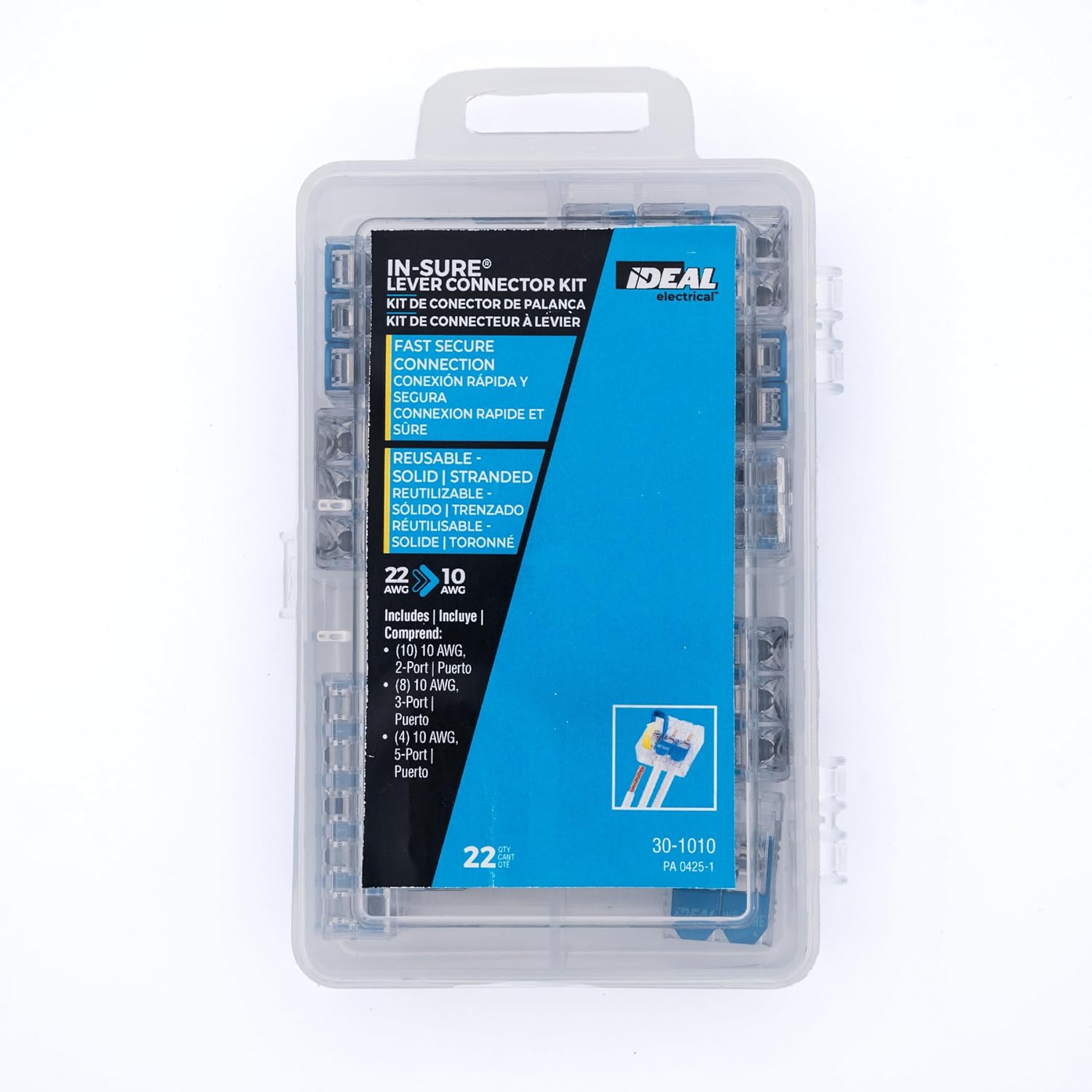
Ideal Industries 30-1010 Lever Connector Kit
- Tool-free lever connections for control wiring
- Handles solid and stranded wire
- Assortment kit — covers multiple wire sizes
- Reusable — open the lever, adjust if needed
Verify Voltage
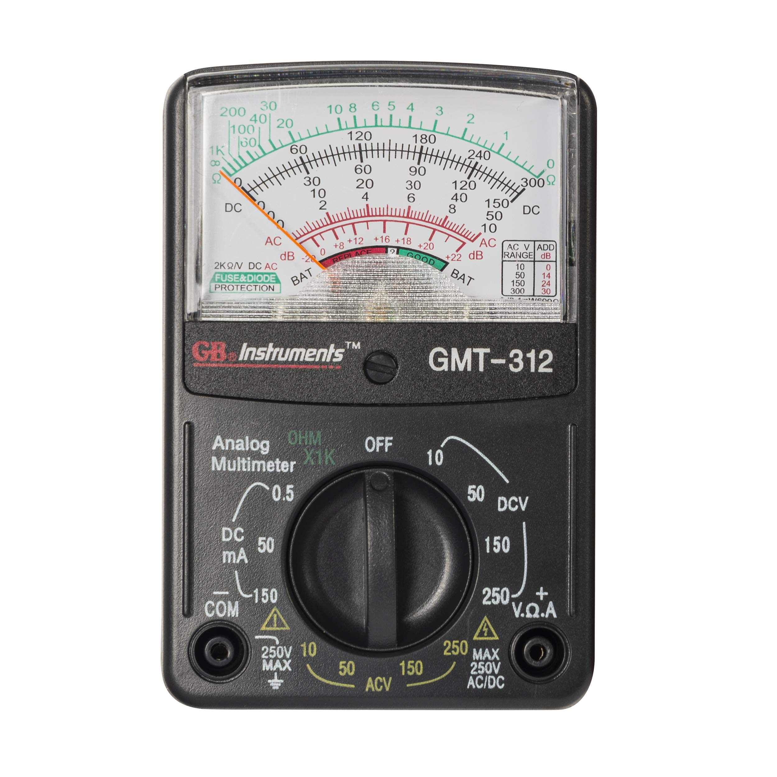
Gardner Bender GMT-312 Digital Multimeter
- Verify motor supply voltage before startup
- AC/DC voltage, resistance, continuity
- Budget-friendly — solid for field verification
- Good backup meter for the job site bag
As an Amazon Associate, TestTalkHQ earns from qualifying purchases.
Pre-Calculated Motor Circuit Sizing Chart (5–150 HP)
Need the answer without opening a calculator? These charts use NEC Table 430.250 full-load current for three-phase induction motors, size the branch conductor at 125% of table FLA (NEC 430.22), pick the smallest THWN-2 copper at 75°C that meets that ampacity (Table 310.16), and list the practical inverse-time breaker at the next standard size at or above 250% of table FLA (NEC 430.52). Dual-element fuse max is 175% of FLA — often one or two sizes smaller than the breaker column.
Wire sizes assume a single set of copper conductors, 75°C terminations, and no ambient/bundling derate. Long runs, aluminum, 90°C columns, and VFD output conductors change the answer — see the voltage-drop section below and verify against the nameplate for overloads.
📋 208 V three-phase — Table 430.250 FLA, 430.22 conductor (125%), THWN-2 Cu 75°C, inverse-time breaker (250% max)
| HP | FLA | Min Cond. Ampacity | Wire (THWN-2 75°C) | Max IT Breaker / Fuse* |
|---|---|---|---|---|
| 5 HP | 16.7A | 20.9A | 10 AWG | 50A |
| 7.5 HP | 24.2A | 30.2A | 8 AWG | 70A |
| 10 HP | 30.8A | 38.5A | 8 AWG | 80A |
| 15 HP | 46.2A | 57.8A | 6 AWG | 125A |
| 20 HP | 59.4A | 74.2A | 4 AWG | 150A |
| 25 HP | 74.8A | 93.5A | 3 AWG | 200A |
| 30 HP | 88A | 110.0A | 2 AWG | 225A |
| 40 HP | 114A | 142.5A | 1/0 AWG | 300A |
| 50 HP | 143A | 178.8A | 3/0 AWG | 400A |
| 60 HP | 169A | 211.2A | 4/0 AWG | 450A |
| 75 HP | 211A | 263.8A | 300 kcmil | 600A |
| 100 HP | 273A | 341.2A | 500 kcmil | 700A |
| 125 HP | 343A | 428.8A | 700 kcmil | 1000A |
| 150 HP | 396A | 495.0A | 900 kcmil | 1000A |
📋 230 V three-phase — Table 430.250 FLA, 430.22 conductor (125%), THWN-2 Cu 75°C, inverse-time breaker (250% max)
| HP | FLA | Min Cond. Ampacity | Wire (THWN-2 75°C) | Max IT Breaker / Fuse* |
|---|---|---|---|---|
| 5 HP | 15.2A | 19.0A | 12 AWG | 40A |
| 7.5 HP | 22A | 27.5A | 10 AWG | 60A |
| 10 HP | 28A | 35.0A | 8 AWG | 70A |
| 15 HP | 42A | 52.5A | 6 AWG | 110A |
| 20 HP | 54A | 67.5A | 4 AWG | 150A |
| 25 HP | 68A | 85.0A | 4 AWG | 175A |
| 30 HP | 80A | 100.0A | 3 AWG | 200A |
| 40 HP | 104A | 130.0A | 1 AWG | 300A |
| 50 HP | 130A | 162.5A | 2/0 AWG | 350A |
| 60 HP | 154A | 192.5A | 3/0 AWG | 400A |
| 75 HP | 192A | 240.0A | 250 kcmil | 500A |
| 100 HP | 248A | 310.0A | 350 kcmil | 700A |
| 125 HP | 312A | 390.0A | 600 kcmil | 800A |
| 150 HP | 360A | 450.0A | 700 kcmil | 1000A |
📋 460 V three-phase — Table 430.250 FLA, 430.22 conductor (125%), THWN-2 Cu 75°C, inverse-time breaker (250% max)
| HP | FLA | Min Cond. Ampacity | Wire (THWN-2 75°C) | Max IT Breaker / Fuse* |
|---|---|---|---|---|
| 5 HP | 7.6A | 9.5A | 14 AWG | 20A |
| 7.5 HP | 11A | 13.8A | 14 AWG | 30A |
| 10 HP | 14A | 17.5A | 12 AWG | 35A |
| 15 HP | 21A | 26.2A | 10 AWG | 60A |
| 20 HP | 27A | 33.8A | 8 AWG | 70A |
| 25 HP | 34A | 42.5A | 8 AWG | 90A |
| 30 HP | 40A | 50.0A | 8 AWG | 100A |
| 40 HP | 52A | 65.0A | 6 AWG | 150A |
| 50 HP | 65A | 81.2A | 4 AWG | 175A |
| 60 HP | 77A | 96.2A | 3 AWG | 200A |
| 75 HP | 96A | 120.0A | 1 AWG | 250A |
| 100 HP | 124A | 155.0A | 2/0 AWG | 350A |
| 125 HP | 156A | 195.0A | 3/0 AWG | 400A |
| 150 HP | 180A | 225.0A | 4/0 AWG | 450A |
* Breaker column = next standard rating ≥ FLA × 250%. Dual-element (time-delay) fuse max = FLA × 175% — select the next standard fuse ≤ that ceiling unless 430.52 exceptions apply. Overload relays still use nameplate FLA (430.32), not this chart.
This chart is the fastest path for a single motor at 208 / 230 / 460 V. For nameplate overload settings, odd voltages, MCP / fuse type swaps, or a full four-element printout, use the Motor Circuit Sizing Calculator. Several motors on one feeder or one branch circuit is a different calculation — see Grouped Motor Circuit Sizing Calculator (NEC 430.24 / 430.53).
Voltage Drop and Run Distance — When to Upsize the Wire
NEC Article 430 sizes motor conductors for ampacity and protection. It does not automatically fix voltage drop. A 460 V motor that is happy on 8 AWG for ampacity can still starve on a 300 ft feeder if you never check drop. Most shops target 3% or less on the branch (5% branch + feeder combined is the common design goal from NEC Informational Notes).
Three-phase voltage drop (copper):
VD = (1.732 × K × I × D) ÷ CM
- K ≈ 12.9 for copper (21.2 for aluminum) at DC resistance approximation used in field tables
- I = motor table FLA (A) — or the continuous current you expect
- D = one-way run length in feet
- CM = conductor circular mils (12 AWG = 6530, 10 AWG = 10380, 8 AWG = 16510, 6 AWG = 26240, 4 AWG = 41740, 2 AWG = 66360, 1/0 = 105600)
Percent drop = (VD ÷ system voltage) × 100. Example: 10 HP at 460 V (14 A table FLA), 200 ft of 12 AWG Cu: VD = (1.732 × 12.9 × 14 × 200) ÷ 6530 ≈ 9.6 V ≈ 2.1% — fine. Stretch that to 400 ft and you are past 4% on the same wire.
📏 Practical upsizing by run length (single motor, copper)
- Under 100 ft: Use the ampacity wire from the chart above. Voltage drop is rarely the driver at 208–460 V unless the motor is soft on voltage or the feeder is aluminum.
- 100–250 ft: Recalculate. Many 208 V and 230 V motors need one AWG size larger than the ampacity minimum to stay near 3%. Prefer checking the formula over guessing.
- Over 250 ft: Expect upsizing — often two sizes or a parallel run on larger HP. Do the math before you pull. Long 208 V runs are the worst offenders because FLA is highest at the lowest voltage.
Undervoltage raises current for the same shaft load. A motor already near service factor on a long feeder will run hot even when the breaker and overload “look” code-correct. If startup is sluggish or the overload trips only on hot days, measure voltage at the motor terminals under load before you blame the heater.
Size ampacity first (chart / calculator), then check drop at FLA for the actual route length. Keep the larger of the two wire sizes. For multi-motor feeders, use the grouped motor calculator for 430.24 ampacity, then run the voltage-drop formula on that feeder current.
Several Motors on One Circuit (NEC 430.24 / 430.53)
Everything above is one motor, one branch circuit. The moment you put two compressors, a conveyor pack, or a machine tool with multiple motors on a shared feeder or a shared branch breaker, Article 430 switches rules:
- NEC 430.24 — feeder conductors supplying several motors: ampacity ≥ sum of all motor table FLAs plus 25% of the highest-rated motor FLA.
- NEC 430.53 — more than one motor on a single branch circuit is only allowed under specific group-protection conditions (430.53(A)/(B)/(C)). The common shop case is 430.53(C): one OCPD for the group, each motor still has its own overload, and the OCPD is capped at Table 430.52 for the largest motor plus the FLA of the others.
Do not size a multi-motor feeder by pretending it is a single motor at the total HP. Use the dedicated tool and walkthrough:
Frequently Asked Questions
Why is the motor breaker allowed to be 250% of FLA?
Because motors draw locked rotor current (LRC) on startup — typically 600–800% of running FLA — for the fraction of a second it takes the rotor to accelerate to running speed. A breaker sized at the standard 125% continuous load rule would trip on every motor start. NEC 430.52 allows up to 250% of FLA for inverse time breakers specifically to ride through this inrush without nuisance tripping. The motor’s separate overload relay, set at 115–125% of FLA, provides the running protection the oversized breaker intentionally cannot.
What is the difference between FLA and LRA on a motor nameplate?
FLA (Full-Load Amps) is the steady-state running current at rated load — the number used for all circuit sizing calculations. LRA (Locked Rotor Amps) is the starting inrush current drawn when the rotor is stationary — typically 600–800% of FLA. LRA is listed on the motor nameplate and used for calculating motor starter and contactor ratings. For branch circuit breaker sizing, you use FLA times the NEC 430.52 multipliers, not LRA directly.
Does NEC Article 430 apply to HVAC compressor motors?
No. Hermetic refrigerant motor compressors — the sealed motors in air conditioners, heat pumps, and refrigeration equipment — fall under NEC Article 440, not 430. Article 440 uses the equipment nameplate MCA and MOP values instead of NEC table FLA values. Always use the HVAC nameplate data for those applications. Trying to apply Article 430 sizing to Article 440 equipment is a common and potentially dangerous mistake.
What size wire for a 5 HP 240V single-phase motor?
From NEC Table 430.248, a 5 HP 230V single-phase motor has an FLA of 28A. Minimum conductor ampacity = 28A times 1.25 = 35A. The minimum wire for 35A at 75°C copper is 8 AWG (rated 50A). Maximum breaker = 28A times 2.5 = 70A. Overload relay set at 28A times 1.25 = 35A. Minimum disconnect = 28A times 1.15 = 32.2A, so a 35A disconnect minimum.
Can the motor branch circuit breaker be smaller than 250% of FLA?
Yes — 250% is the maximum, not the required size. If the motor reliably starts on a smaller breaker, you can use it. Many installers use 200–225% in practice as a balance between fault protection and inrush clearance. If the motor nuisance-trips a breaker at or below the 250% maximum, NEC 430.52(C)(1) allows you to increase to the next standard size up to the table maximum.
Is a motor overload relay the same as a circuit breaker?
No — they’re fundamentally different devices that do different jobs. A circuit breaker protects the branch circuit conductors from short circuits and overcurrent, and is intentionally sized at 250% of FLA to survive motor inrush. A motor overload relay protects the motor windings from thermal damage due to sustained overloads, and is sized at 115–125% of FLA for precise thermal protection. Both are required in a compliant motor circuit. The breaker alone — without an overload relay — is not adequate motor protection because it’s too large to trip on most overload conditions.
Get All Four Motor Circuit Values Instantly
Our free motor FLA calculator covers single-phase and three-phase motors from 1/6 HP to 50 HP at all standard voltages. Enter HP and voltage — get conductor size, maximum breaker, overload relay setting, and minimum disconnect in one calculation.
See also: Motor Circuit Sizing Calculator — NEC 430 Conductors, Breaker, Overload & Disconnect and Motor Circuit Sizing Guide — Conductors, Breakers, Overloads & Disconnects per NEC 430.
Motor FLA Troubleshooting — wrong table, SFA, voltage mix-ups.
Motor OCPD: Breaker vs Fuse vs MCP — which branch device to use.
Motor Circuit Sizing Chart — shared FLA and 430.52 multipliers.
A compressor or machine tool on belts changes shaft RPM before FLA is a nameplate fact. Size the drive with the Pulley & Belt Ratio Calculator, the pulley ratio guide, and the sheave size chart.
Motor Circuit Sizing Troubleshooting — trips, hot conductors, overloads.
Electrical
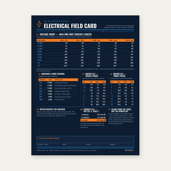
Electrical Reference Card
One page. Voltage drop lengths, breaker and wire pairing, motor FLC.
$3.99
Buy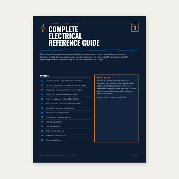
Complete Electrical Reference Guide
15 pages. Ampacity, corrections, voltage drop, motor circuits, conduit fill.
$12.99
Buy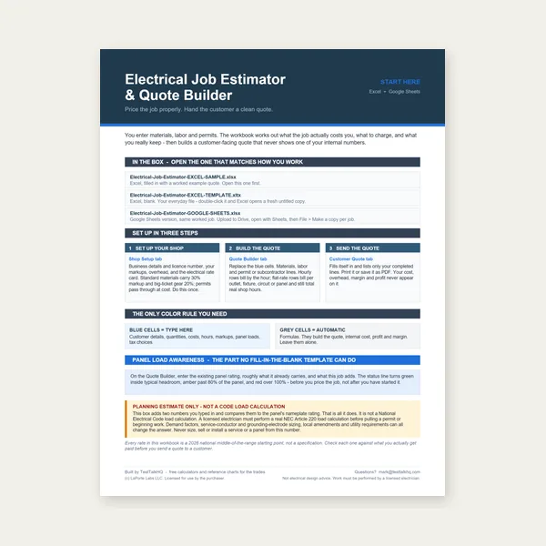
Electrical Job Estimator
Quote electrical work and flag panel headroom before you price it.
Excel or Google Sheets. Best on a computer.
$29.00
Buy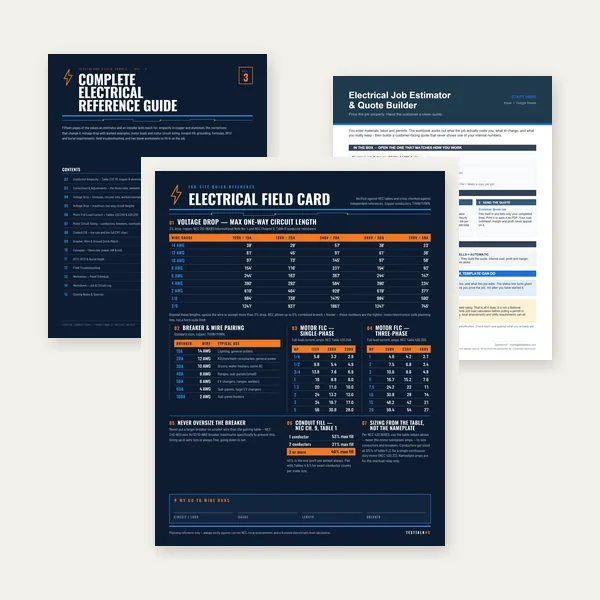
Electrical Complete Bundle
Card, 15-page guide and the estimator workbook. All six files.
Excel or Google Sheets. Best on a computer.
$34.99
$45.98 if bought separately — save $10.99
BuyCheckout opens in a new tab.