A measuring procedure you can finish in an afternoon, and a worked example done entirely by hand
You can calculate a brake system in about ten minutes. Measuring it honestly takes an afternoon, and that is the part that decides whether the answer is worth anything. Below is the order to do it in, what each measurement is actually of, the specific way each one gets taken wrong, and then the whole chain worked through by hand on one real set of numbers so you can see what every step does to the answer.
Six numbers per end, four for the car
Here is the full input list, and nothing else matters:
| Measurement | What it is | Where it comes from |
|---|---|---|
| Pedal ratio | Mechanical leverage of the pedal arm | Two tape or caliper measurements on the pedal box |
| Master cylinder bore | Area the pushrod load works on | Caliper on the bore, or the casting mark, or the data sheet |
| Caliper piston area, one side | Area the line pressure works on | Caliper on each piston bore, or the caliper data sheet |
| Effective rotor radius | Lever arm the pad friction acts through | Swept outside diameter and pad radial height |
| Pad coefficient of friction | How much of the clamp becomes drag | The pad manufacturer’s published friction data, nowhere else |
| Tyre loaded radius | Lever arm from brake torque to road force | Ground to axle centre, with the car’s weight on it |
Plus four numbers that describe the car rather than the brakes: total weight, the static front share, the wheelbase and the centre of gravity height. Those four decide the ideal split, and they are the reason a brake system that is right on one car is wrong on another with identical brakes.
Step 1 — pedal ratio, and the mistake everyone makes
Wilwood’s definition is the one to use, and it is simple: “Pedal ratio is calculated by measuring the straight line distance from the center point of the pedal pivot to the middle of the foot pad (measurement A) and then dividing that number by the distance from the center point of the pedal pivot to the center point of the pushrod attachment location (measurement B).”
So: A ÷ B. Two notes that save arguments. First, both are straight-line distances, not distances along the curve of the pedal arm — a bent pedal arm will give you a longer answer if you follow the metal. Second, Wilwood add this explicitly: “It does not matter if the pushrod attachment point is above or below the pedal pivot point. The calculation of the pedal ratio is still the same formula of A divided by B.”
What you get for it, in Wilwood’s own worked example: “If 100 pounds of force is applied to a pedal with a 5:1 ratio, 500 pounds of force would be applied to the master cylinder pushrod.” And the price, in the same breath: “For every 1.00 inch of stroke travel in the master cylinder piston, the pedal will move 5.00 inches.” Leverage multiplies travel exactly as much as it multiplies force. There is no version of this where you get one without the other.
If you are designing rather than measuring, Wilwood’s starting point is 6:1, which they call “an excellent starting point” when the right ratio is unknown. In practice manual-brake cars sit around 6:1 to 7:1 and boosted cars nearer 4:1, because the booster is supplying the rest of the multiplication.
Step 2 — master cylinder bore, the inverse-square lever
Pressure is pushrod force divided by bore area, and bore area is π/4 times the bore squared. That squared term is why this is the strongest single lever in the system. Going from a 1.000 in bore to a 7/8 in bore is (1.000 ÷ 0.875)² = 1.31, so 31 percent more pressure for exactly the same foot. Nothing else on the car is that cheap.
It is also the first thing Wilwood blame when a car will not stop: “Common contributors to ‘hard pedal, won’t stop’ issues are an oversized master cylinder bore and/or inadequate pedal lever ratio.”
Measure the bore if you can get a caliper into it; otherwise take it from the casting mark or the part number. What you must not do is assume it from the car’s model year, because master cylinders are the single most swapped part in a brake system and a “stock-looking” one off a heavier model is a very common find.
Step 3 — caliper piston area, counted on one side
This is the input that is wrong most often, and the rule is published and unambiguous. Wilwood: “A calipers piston area is calculated by finding the total piston area from one side of the caliper (this is true for a single piston caliper also). … Note that differential piston bore calipers will be the total piston area of the different size pistons.”
So on a four-piston fixed caliper you add the two pistons on one side. On a six-piston caliper, three. On a floating single-piston caliper, the one piston. The reason is mechanical: the caliper presses both pads with the same load, so one side’s area times line pressure is the clamp force acting on each face of the rotor — and that is also exactly why the torque step carries a factor of two for the disc’s two friction faces. Count both sides and you double your torque and will cheerfully convince yourself a front axle locks when it does not.
Note the differential-bore warning, because performance calipers are built that way deliberately. Wilwood explain why: “Wilwood calipers have bore sizes that increase in size from front to rear. This allows a pressure differential between the leading and trailing edge of the caliper, thus providing a more even wear pattern along the entire length of the brake pad, hence it controls pad taper.” If the two bores on one side are not equal, you cannot multiply one diameter by a count — add the actual areas.
| Caliper | Pistons to count | Why |
|---|---|---|
| Single-piston floating | 1 | The caliper body slides and reacts the load on the other pad |
| Two-piston floating (both on one side) | 2 | Both are on the same side; that is the side total |
| Four-piston fixed | 2 | Two per side, and you want one side |
| Six-piston fixed | 3 | Three per side |
| Six-piston differential bore | 3, by area not by count | The three diameters on that side are not equal |
Step 4 — effective radius from the swept band
The effective radius is where the pad’s friction effectively acts, and it is not the rotor radius. The pad covers a band, and the honest shorthand is the middle of that band:
Effective radius = (swept outside diameter ÷ 2) − (pad radial height ÷ 2)
Two things to be careful about. The swept outside diameter is the polished ring the pad actually touches, which is smaller than the rotor blank — look at any used rotor and the unswept lip at the outer edge is obvious. And pad radial height is measured across the pad from its inner edge to its outer edge, not along the rotor.
On a 12.19 in swept diameter with a 1.90 in pad, that is 6.095 − 0.95 = 5.145 in. Using the rotor radius of 6.095 instead would inflate every brake torque downstream by about 18 percent, which is the difference between a car that locks its front axle and one your spreadsheet says locks its rear.
Step 5 — pad friction, the one you cannot measure
Everything else on this list you can put a tool on. The pad’s coefficient of friction you cannot, and there is no honest substitute for the manufacturer’s published friction data at the temperature you care about.
Three things worth knowing before you reach for a number:
- It is not one number, it is a curve against temperature. That is literally what fade is — the coefficient dropping as the pad goes past its range. A figure taken at one temperature describes the car at one temperature.
- Different compounds front and rear move your bias when the brakes get hot. This is the quietest way to build a car that behaves cold and locks its rear axle on the fifth stop down a hill, because the two ends fade at different rates. If you change one end’s compound, you have changed your bias, and you have changed it in a way that only shows up when it matters.
- Wilwood list pad aggressiveness directly as a contributor to a car that will not stop, alongside the bore and the pedal ratio. A hard street compound in a system that cannot make much pressure is a bad pairing.
Any trade
Contractor Job Estimator
Price remodels and GC work, then send a quote with no internal numbers.
Excel or Google Sheets. Best on a computer.
$29.00
BuyCheckout opens in a new tab.
What you need to measure it
Every number in this procedure is a measurement. None of them is a lookup, and the two that people get wrong most often — piston bore and swept diameter — are the two that a caliper settles in thirty seconds. One tool we would list and cannot: Wilwood’s own advice when the pressure does not add up is to fit a gauge at the caliper and read it, and we have no verified affiliate link for a brake line pressure gauge, so there is no guess in that slot.
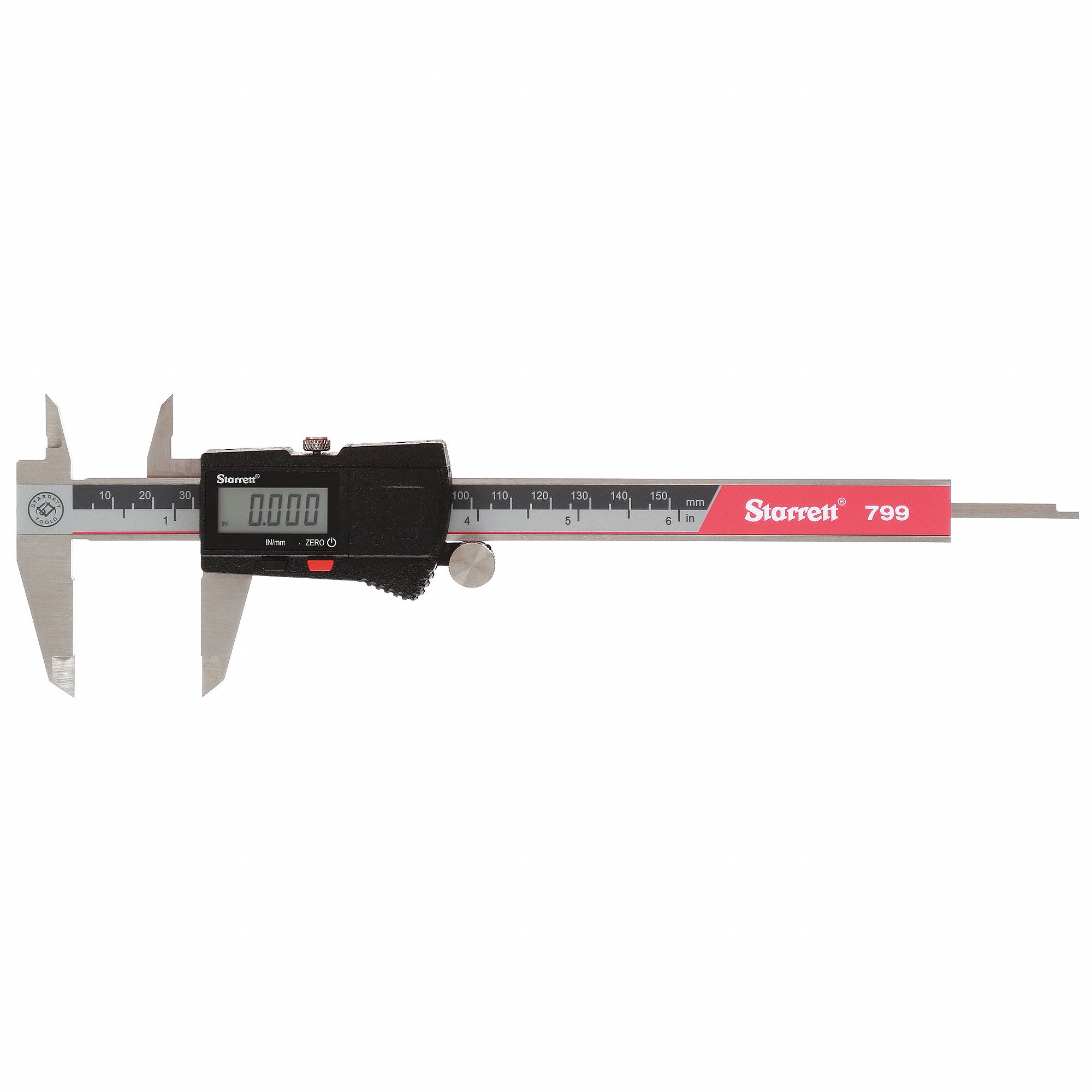
Starrett EC799A Electronic Caliper 0‑6"
- Piston bores, swept diameter and pad radial height in one pass
- Clamp load goes as the square of bore, so this is the sensitive one
- Also measures pedal arms A and B honestly, which a tape does not
Lisle 81850 Brake Lining Thickness Gauge Set
- Uneven wear front to rear is a bias change nobody chose
- Checks the lining without stripping the caliper off the car
- Tells you whether the friction figure you looked up still applies
8MILELAKE 24‑Piece Caliper Compressor Set
- You cannot count pistons on one side without opening the caliper
- Pushes the piston back without destroying the dust boot
- Performance calipers often run unequal bores on the same side
OMT One‑Man Brake Bleeding Kit
- Air is compressible; this whole calculation assumes the fluid is not
- Wilwood’s first answer to a spongy pedal is air in the system
- A vacuum bleeder also makes the gauge port easy to reach
EPAuto 1/2" Drive Click Torque Wrench
- Caliper brackets carry every pound of the torque you just calculated
- A front axle making 3,000 lb-ft wants its mounts done to spec
- 10 to 150 lb-ft covers caliper, bracket and lug torque on most cars
As an Amazon Associate, TestTalkHQ earns from qualifying purchases. Prices and availability can change.
Step 6 — the four numbers that describe the car
These do not touch your line pressure at all. They decide what the ideal split is, and therefore whether the split you have is safe.
- Total weight and the static front share. Scales, with the driver in and the fuel it normally carries. Front-engine front-drive cars run 60 to 65 percent front, a front-engine rear-drive sedan 52 to 56, a mid-engine car can be under 45. Guessing this five points wrong moves everything.
- Wheelbase. Front wheel centre to rear wheel centre. Easy, and it only ever appears as the ratio of centre of gravity height to wheelbase.
- Centre of gravity height. The one nobody measures. There is a proper method — weigh one axle level, then weigh it again with that axle raised a known height and work back — and for most people a careful estimate is what actually happens. A low sports car is 16 to 18 in, a sedan 20 to 22, a crossover 24 to 27, a lifted truck past 30.
- Tyre loaded radius. Ground to axle centre line with the weight on it, which is roughly three percent less than half the free diameter. If you only have a sidewall marking, the tyre size calculator converts it.
The whole thing worked by hand
One set of numbers, start to finish, so you can check your own arithmetic against something.
The car: 3,400 lb, 55 percent front (so 1,870 lb front and 1,530 lb rear), 108 in wheelbase, 20 in centre of gravity, 12.5 in tyre loaded radius.
The pedal: 100 lb of foot, 6:1 ratio, no booster.
The hydraulics: one 0.875 in bore tandem master cylinder, no proportioning valve.
The front brakes: two calipers, two 1.75 in pistons per side, 12.19 in swept diameter, 1.90 in pad, μ = 0.40.
The rear brakes: two calipers, one 1.12 in piston per side, 11.75 in swept diameter, 1.60 in pad, μ = 0.38.
| Step | Arithmetic | Result |
|---|---|---|
| Pushrod force | 100 × 6 × 1.00 | 600 lb |
| Master cylinder area | π/4 × 0.875² | 0.6013 sq in |
| Line pressure | 600 ÷ 0.6013 | 998 psi |
| Front piston area, one side | 2 × π/4 × 1.75² | 4.811 sq in |
| Front clamp per caliper | 998 × 4.811 | 4,800 lb |
| Front effective radius | 12.19/2 − 1.90/2 | 5.145 in |
| Front torque per rotor | 2 × 0.40 × 4,800 × 5.145 ÷ 12 | 1,646 lb-ft |
| Front axle torque | × 2 calipers | 3,293 lb-ft |
| T₁, front road force | 3,293 × 12 ÷ 12.5 | 3,161 lb |
| Rear piston area, one side | 1 × π/4 × 1.12² | 0.985 sq in |
| Rear clamp per caliper | 998 × 0.985 | 983 lb |
| Rear effective radius | 11.75/2 − 1.60/2 | 5.075 in |
| T₂, rear road force | 2 × 0.38 × 983 × 5.075 × 2 ÷ 12.5 | 607 lb |
| Braking ratio z | (3,161 + 607) ÷ 3,400 | 1.108 g asked for |
| Hydraulic front share | 3,161 ÷ 3,768 | 83.9 percent |
Pause on two of those. The 998 psi sits right inside the band Wilwood say a disc brake needs — “Disc brakes require approximately 900-1200 psi at the caliper for effective functioning” — so the leverage side of this car is correctly specified. And the hydraulics are asking for 1.108 g, which is more than any tyre on a dry road will give you. That is normal and it is not the answer. The answer is which axle runs out first.
And then the part that actually matters
FMVSS 135 S7.4.4(g) gives the adhesion each axle is being asked for. The weight that moves forward is z h P / E, so at a braking ratio of 1.108 on this car that is 1.108 × 20 × 3,400 ÷ 108 = 698 lb. The front is therefore carrying 1,870 + 698 = 2,568 lb and the rear has 1,530 − 698 = 832 lb left. Then:
- f₁ = 3,161 ÷ 2,568 = 1.23 — the front is being asked for 1.23 times its own weight in grip, and the dry test surface in FMVSS 135 S6.2.1 offers a peak friction coefficient of 1.02. The front axle locked a while ago.
- f₂ = 607 ÷ 832 = 0.73 — the rear is nowhere near.
Scale back until f₁ equals 1.02 and you get the real answer: the front axle locks at a braking ratio of 0.863, on 78 lb of pedal. The rear would not lock until 1.31, which is unreachable. So 0.863 g is what this car does, 78 lb is what it costs, and from 60 mph that is about 139 ft of braking distance.
Front first, which is the sequence FMVSS 135 S7.2.1 requires: “lockup of both front wheels occurs either simultaneously with, or at a lower deceleration rate than, the lockup of both rear wheels” for first-axle lockup anywhere from 0.15 to 0.80. This car passes.
Where to put the crossover
Your hydraulic front share is flat. The ideal front share is P₁/P + z h / E, a straight line rising with deceleration. On the worked car that is 0.55 + z × 0.1852, so 55 percent at a standstill, 64 percent at 0.5 g, 70 percent at 0.8 g, 74 percent at 1.0 g.
A flat line and a rising line cross exactly once. At 83.9 percent, this car’s crossover is at z = (0.839 − 0.55) ÷ 0.1852 = 1.56 g, which is well above anything the tyres can deliver. In other words it is front-biased everywhere in the usable range, which is exactly where you want to be.
That is the design target, and it is deliberately not “balanced”: put the crossover at or above the hardest stop the car will ever make, so you spend the whole usable range on the safe side of it. It costs you a little distance on gentle stops, because the rear tyres are under-used. It buys you a car that never locks a rear axle.
And note what you cannot do with a fixed split: you cannot follow a rising curve with a flat line. The only adjustment that bends the line rather than tilting it is a proportioning valve, which is the whole argument in valve vs bore vs balance bar.
Check it loaded as well as empty
Everything above was one load case. FMVSS 135 runs every braking test at both gross vehicle weight rating and lightly loaded vehicle weight, and the lock-sequence requirement has to be met in both. The reason is in the equations: loading changes P₁, P₂, P and usually h too.
Put 1,000 lb in the back of a pickup and the rear axle gains static weight, so it takes far more rear brake torque to lock it — the rear is now badly under-used. Take it out and the same hydraulics can lock the rear easily. This is not a subtlety; it is the single biggest reason factory proportioning valves exist and why load-sensing versions exist on vans and trucks. Work your real axle loads out with the payload capacity calculator and run the brake maths twice.
Frequently asked questions
What order should I measure a brake system in? Pedal ratio first, because it costs nothing and is often not what the catalogue says. Then the master cylinder bore, because line pressure varies as one over the bore squared and nothing downstream is meaningful with the wrong one. Then the caliper piston area and the swept rotor dimensions at both ends, which is wheels-off work. Pad friction coefficient last, because it is the only input you cannot measure yourself and you want to know early whether the manufacturer publishes it.
How exact does the centre of gravity height need to be? It appears only as the ratio of centre of gravity height to wheelbase, so on a 108 in wheelbase a two-inch error changes the weight-transfer term by about ten percent, which moves the ideal front share by roughly two points. That is enough to matter when you are close to the crossover and not enough to change a clearly front-biased answer. If you are estimating, estimate low: a high value makes the maths flatter a rear-biased system.
Can I use the rotor diameter instead of the effective radius? No. The pad acts across a band, not at the rotor’s outer edge, so using the rotor’s outside radius overstates brake torque by roughly fifteen to twenty percent on a typical disc. Use the swept outside radius minus half the pad’s radial height, or better, the effective radius the caliper or kit manufacturer publishes.
Why does the lock-up order not depend on the master cylinder bore? Because the bore changes the pressure in both circuits by the same factor, so it changes how much pedal force you need but not the ratio of front to rear brake torque. The lock-up order is set by that ratio against the dynamic axle loads. A bore change moves the pedal effort; a caliper, pad or valve change moves the bias. They are separate problems.
What line pressure should I be seeing? Wilwood’s published figure is that disc brakes require approximately 900 to 1200 psi at the caliper for effective functioning, and their recommendation when the maths and the pedal disagree is to fit a gauge and read the actual pressure rather than trusting the calculation. If you are short, the fixes in order of effectiveness are a smaller master cylinder bore and then a higher pedal ratio.
How do I know the pedal ratio I measured is right? Cross-check it against travel. Wilwood’s relationship works both ways: at a five to one ratio, one inch of master cylinder stroke is five inches of pedal movement. Measure how far the pedal moves and how far the pushrod moves over the same stroke and the ratio of those two distances must match the ratio of your two arm lengths. If it does not, one of your measurements is wrong, usually measurement A taken to the top of the pad rather than the middle.
Do I need to redo this after a brake pad change? If you fit the same compound, no. If you fit a different compound at one end only, yes, and it matters more than people expect: the pad coefficient of friction is a direct multiplier on that axle’s torque, so changing it at one end shifts the bias at once, and because the two compounds then fade at different rates it also shifts the bias as the brakes get hot.
What about rear drum brakes? They cannot be done this way. A drum’s leading shoe is dragged into the drum by its own friction, which multiplies the torque by a self-energising brake factor somewhere between roughly two and four depending on geometry and lining. That figure is measured on a dynamometer and cannot be derived from a wheel cylinder bore and a lining friction coefficient, so the only honest route is to get it from the drum’s published data.