
The four arrangements the Copper Tube Handbook points at, compared on the things that actually decide it — space, joint count, maintenance and who carries the design responsibility
The handbook lists the options and leaves the choice to you
Once you know how far a run moves, the remaining question is what to put in its way. The Copper Tube Handbook names the candidates in a single sentence and then says nothing about choosing between them: stresses, buckles and bends “are prevented by the use of expansion joints or by installing offsets, ‘U’ bends, coil loops or similar arrangements in the tube assembly. These specially shaped tube segments take up expansion and contraction without excessive stress.”
That gives four practical arrangements. Three of them are made out of copper tube and are sized by the handbook’s own formula and Table 14.8. The fourth is a manufactured component and is sized by whoever makes it. Keeping that distinction clear is most of the decision.
1. The coiled loop
A full circle of tube in the line. The handbook tabulates it as a radius, and because a complete coil’s circumference is its developed length, the radius is simply that length divided by 2π. For 1 in tube absorbing an inch of movement the developed length is about 8 ft, which rolls to a coil roughly 15 in in radius — two and a half feet across.
Where it wins. It is the lowest-joint option there is: formed from annealed coil, a loop can be a single continuous piece of tube with no fittings in it at all. The handbook notes that “annealed temper tube in coils permits long runs without intermediate joints”, and since every joint inside a flexing element is a stress riser, zero joints is a real advantage. It is also symmetrical, so it behaves the same in expansion and contraction.
Where it loses. It needs a clear cylindrical volume, often in a plane the building does not offer. A 2 in main needing 13 ft of developed length wants a coil over four feet across, and there is rarely a ceiling void that shape. It also traps air at the top and, in a horizontal orientation, water at the bottom — which matters on a system that has to be drainable or vented.
2. The expansion offset, U-bend or dogleg
The same developed length, folded into a rectangle instead of a circle: two 90s out, a leg across, two 90s back. Table 14.8 gives the developed length directly for this case and you distribute it over the geometry.
Where it wins. It fits buildings. Offsets go along joists, up into a ceiling void, around a beam, and they can be stretched in whichever direction there is room. On retrofit work this is nearly always the practical answer. It can also often be arranged to double as a drainable high or low point rather than fighting one.
Where it loses. Four elbows. That is four joints inside the element that is deliberately being flexed, plus the pressure drop of four changes of direction. It also matters a great deal how you distribute the length: a tall thin U with most of the length in the crossing leg behaves quite differently from a squat wide one, and the handbook’s figure shows a specific proportioning rather than leaving it free. If the shape you can fit is very different from the figure, you are outside the published case and should get it looked at properly.
3. Natural flexibility and swing arms — the option you may already have
A run that changes direction already contains an offset; it just was not drawn as one. A branch that leaves a main, turns, and runs a few feet to a riser is a swing arm, and the torsional and bending flexibility of those legs absorbs movement at the connection without any added component.
Where it wins. It costs nothing and adds no joints, because it is the layout you were building anyway. On branch connections off a long main it is the standard approach: you take the branch off at a point where the main’s movement can be swallowed by the branch’s flexibility, rather than teeing straight into a rigid drop.
Where it loses. It is the hardest to prove. The handbook’s formula sizes a loop or an offset of a known shape; it does not tell you how much movement an arbitrary set of bends in your layout will absorb. If you are relying on natural flexibility on anything long, hot or large, that is an engineering judgement rather than a table lookup — and the honest answer is sometimes to add a deliberate offset so the number is defensible.
The failure mode to watch: relying on a change of direction that someone later anchors. A swing arm only works if the leg is free to flex, so a strap on the short leg kills it.
The two inputs people guess, and the tools that stop them guessing
Of the four things that set the movement, two are temperatures, and on most jobs both are assumed rather than measured. An assumed 140°F against an actual 180°F is a third more movement, which is a third more loop. These are the instruments that replace the assumption, and the tools for the physical half of the work.
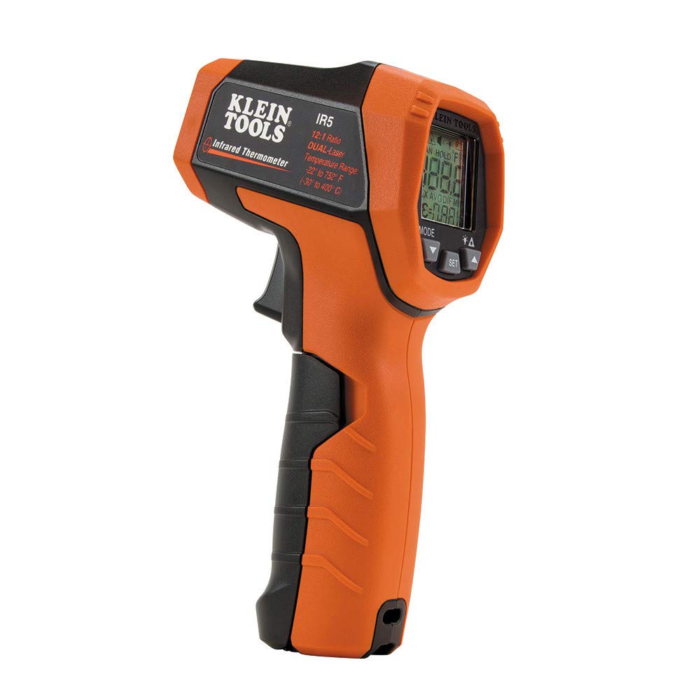
Klein Tools IR5 Dual‑Laser Infrared Thermometer
- Reads the tube surface, which is the number the calculation wants
- Dual laser frames the spot, so you measure pipe and not insulation
- Catches the case people miss: a recirculation return near supply temperature all day

Fieldpiece ST4 Dual Temperature Meter
- Two clamp probes give the real swing across a run, not one snapshot
- Log the cold start and the hot running condition on the same line
- The honest way to replace an assumed 70°F installation temperature
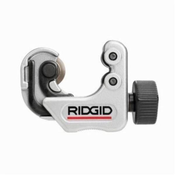
RIDGID 32573 Model 118 Close‑Quarters Tubing Cutter
- Square cuts on the legs of an offset, in the joist bay where it has to go
- Built-in reamer, because a burr inside a bend is a velocity problem later
- Close-quarters body for the tight retrofit a loop always turns into

Fluke 62 Max Industrial Infrared Thermometer
- Range and accuracy for the 180°F+ mains where movement gets serious
- Drop rated for the plant room rather than the job box
- Narrow spot ratio, so you read the tube and not the lagging beside it
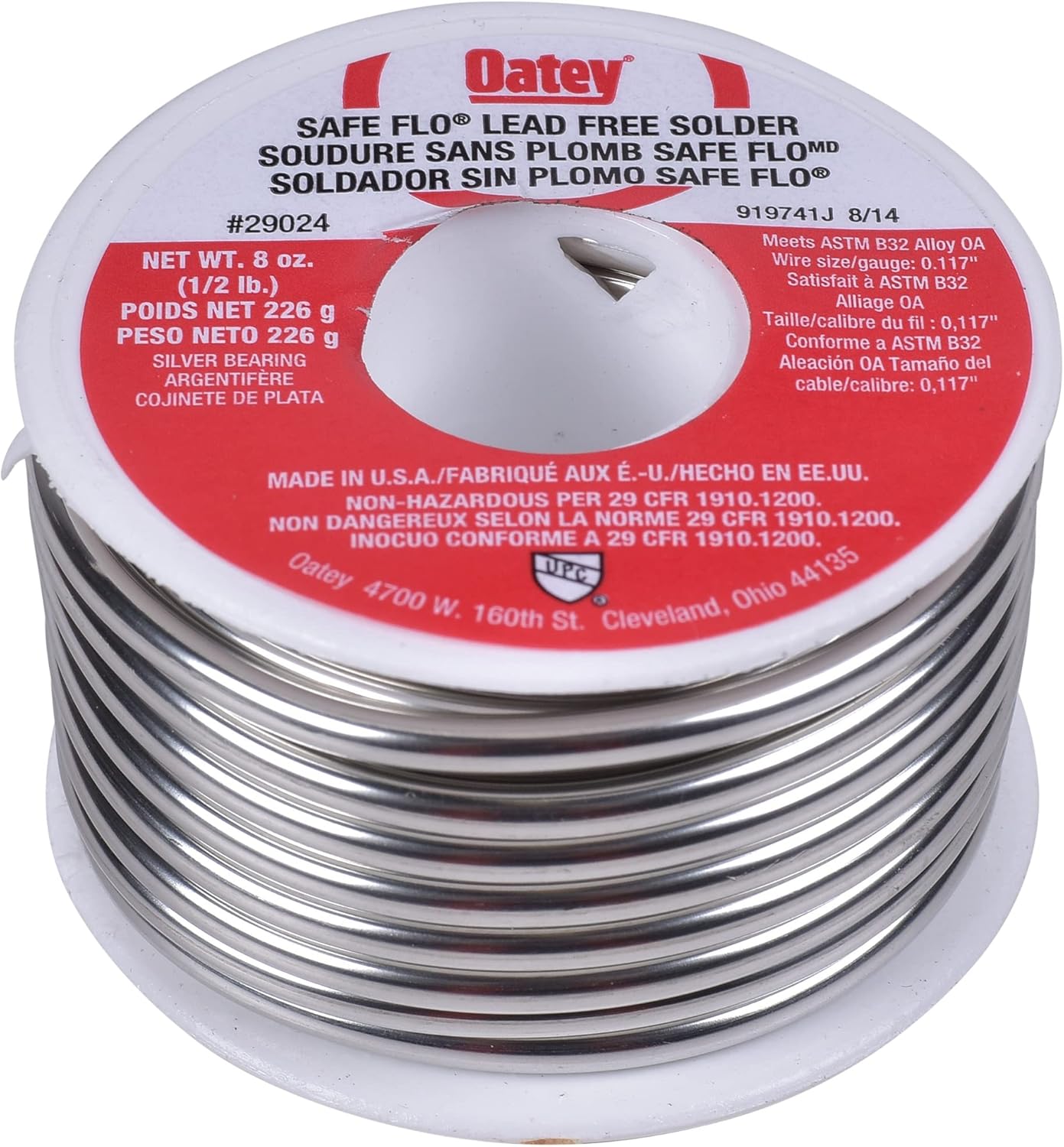
Oatey 29024 Safe‑Flo Lead‑Free Solder
- Lead-free, for the elbows an offset adds to a potable line
- Fewer and better joints inside a loop: every one is a stress riser
- The alloy the published potable joint ratings assume
As an Amazon Associate, TestTalkHQ earns from qualifying purchases. Prices and availability can change.
4. Mechanical expansion joints, bellows and flexible connectors
A manufactured component: a bellows, a slip or packed joint, or a braided flexible connector, rated for a stated amount of travel. The handbook lists expansion joints first among the options but publishes no sizing data for them, and that is the key fact about this route.
Where it wins. Travel in almost no space. Where a 2 in run needs thirteen feet of developed copper and there is nowhere to put it, a bellows rated for an inch and a half of axial travel occupies a few inches of pipe length. On tight plant rooms, risers and anywhere a loop simply will not fit, this is often the only answer. Manufactured joints also come with a published travel rating you can put in a submittal, which is sometimes worth more than the hardware.
Where it loses. It is a component with a service life in a system that may outlast it, and it only works if it is installed exactly as the maker specifies — which always means a real anchor at one end and correct guides at a stated spacing, because a bellows that is allowed to buckle sideways instead of compressing axially fails fast. It costs materially more than tube and elbows. And crucially: the sizing and the installation rules come from the manufacturer, not from the Copper Tube Handbook and not from this site. If you choose this route, the published travel rating and the guide spacing in the manufacturer’s instructions govern.
Side by side
| Coiled loop | Offset / U-bend | Natural flex / swing arm | Mechanical joint | |
|---|---|---|---|---|
| Sized from | CDA formula and Table 14.8 radius | CDA formula and Table 14.8 developed length | Engineering judgement — no published table | Manufacturer travel rating |
| Joints added | None if formed from coil | Four elbows typically | None | Two, plus the component |
| Space needed | A clear circle, often large | Flexible shape, fits buildings | None extra | Very little |
| Material cost | Low — tube only | Low — tube and elbows | Nil | Highest |
| Labour | Forming the coil | Four joints to make well | Nil | Low, but fussy to get the guides right |
| Service life concern | None beyond the tube | None beyond the joints | Someone anchoring the flexible leg later | A wearing component to inspect and eventually replace |
| Air and drainage | Traps air or water depending on orientation | Can be arranged to help | Neutral | Neutral |
| Easy to prove on paper | Yes | Yes | No | Yes, via the data sheet |
Run your own numbers. The copper pipe expansion loop calculator takes the size, the run between anchors and the two temperatures, and returns the movement, the developed length the CDA formula requires, the coil radius to roll it to, the published Table 14.8 figure beside it and the support spacing for the run.
The option that is not on the list: move the anchors
Before choosing any of the four, consider changing the question. Movement goes with the length between anchors, and the loop goes with the square root of the movement. Split a run in half with a mid-point anchor and each half moves half as far, so each loop is about 70 percent of the original size — two loops at 70 percent against one at 100 percent is more total tube, but each individual element is small enough to fit, which is usually the binding constraint rather than material cost.
Worked on a real case: a 2 in main, 100 ft, 70 to 200°F, moves 1.466 in and needs 13.6 ft of developed length — a coil over four feet across that will not fit anywhere. Anchor it in the middle and each 50 ft half moves 0.733 in and needs 9.6 ft, a coil about three feet across. Still big, but now it is an offset along a joist line instead of an impossibility.
Six steps, in this order
- Get the real temperatures. Surface-measure the tube cold and hot rather than assuming 70°F and the thermostat setting. This is where the biggest errors live.
- Decide where the anchors go, deliberately. Then recheck the run for accidental anchors that would override your decision.
- Work out the movement per section — ΔT × run in feet × 12 × 0.0000094 — and ask whether splitting any section makes the rest of the job easier.
- Look at the layout before adding anything. If the run already changes direction between the anchors, you may have the flexibility you need; on short, small, moderate-temperature branches this is often the real answer.
- If you need a deliberate element, get the developed length from the formula and the Table 14.8 cell, and build to the longer of the two. Then choose coil or offset purely on what fits and how many joints you want.
- Only reach for a mechanical joint when geometry forces it, and then follow the manufacturer’s anchor and guide instructions exactly, because that is what the rating depends on.
Steps three and five are what the expansion loop calculator is for. The full method behind them is in the copper expansion loops guide, and if you are working on a system that is already failing, start instead with when a copper line ticks, bows or splits a joint.