
A dry-bulb split sees only sensible heat. Adding a wet bulb at the return and the supply turns four temperatures and an airflow into total, sensible and latent capacity in BTU per hour. Where to put the probes, how to get a defensible CFM, why site elevation is not a rounding error, what the psychrometrics actually do with your readings, how to read the result, and a worked three-ton example from measurement to conclusion.
What the air-side method actually measures
There are two honest ways to find out how much cooling a piece of equipment is producing. You can measure the refrigerant — mass flow and the enthalpy change across the evaporator — which is accurate and needs instrumentation most vans do not carry. Or you can measure the air: how much of it is moving, and how much energy it lost crossing the coil. That second one needs a thermometer, a humidity reading and an anemometer, and it is the method this guide is about.
It is not a shortcut or an approximation of the refrigerant method. It is a straight energy balance on the airstream, and if the six inputs are good the answer is good. Ed Janowiak, who runs HVAC design education for ACCA, describes it plainly on the association’s blog:
The “little bit of math” is what the calculator does. What this guide covers is everything that happens before it: what to measure, where, with what, and in what order.
The six numbers, and how much each one matters
| Input | What it does to the answer | How careful to be |
|---|---|---|
| Airflow (CFM) | Multiplies every BTU figure, linearly | Very. 10% out means every BTU figure is 10% out |
| Supply wet bulb | Sets the latent half almost single-handedly | Very. Half a degree moves latent by roughly a fifth |
| Return wet bulb | Sets the entering moisture and the air density | Careful, but the coil gives you more margin here |
| Return dry bulb | Sensible split, plus specific volume | Normal care; a degree is a degree |
| Supply dry bulb | Sensible split | Normal care |
| Site elevation | Sets barometric pressure, and therefore air density | Look it up once. It is not a small correction |
Sensitivities computed from the ASHRAE psychrometric relations in chapter 1 of the Handbook—Fundamentals; the supply wet-bulb figure is reproduced case by case in the table under the calculator’s results.
Step 1 — get the airflow right first
Do this before anything else, because if you cannot get a defensible airflow number the rest of the exercise produces a defensible-looking wrong answer. There are three routes, in descending order of trust:
- A duct traverse. A hot-wire anemometer on a telescoping probe, taken on a grid across a straight section of duct, averaged, times the duct area. This is the reference method and it is what the others are trying to approximate.
- A flow hood on every supply register. Add them up. Honest, slow, and it misses duct leakage between the coil and the boots — which, depending on the house, is either nothing or a great deal.
- Total external static pressure against the blower table. Measure the static, look up the CFM the manufacturer publishes for that blower speed at that static. Fast, and only as good as the table and the assumption that the blower is behaving.
Step 2 — the four temperatures, and where to stand
You need dry bulb and wet bulb at two places: entering the coil and leaving it. Simple to say; there are four ways to get it wrong.
Return side
Take it in the return plenum, as close to the coil as you can get a probe, and not at the thermostat. A return drop running through an unconditioned attic or crawl space arrives warmer and often wetter than the air that left the room, and that difference is real load the equipment is carrying. Measuring at the thermostat tells you about the room. Measuring at the coil tells you about the equipment, which is what a capacity measurement is for.
Supply side
Downstream of the coil, and deliberately out of line of sight of it. A cold coil is a radiant surface, and an infrared thermometer or an exposed thermocouple looking straight down the barrel at it reads several degrees low. A few feet downstream, or around a bend, removes that.
Wet bulb, specifically
A sling psychrometer wants a full minute of steady swinging, and you take the lowest reading it settles on, not the first one that looks plausible. A dry or dirty wick reads high — toward the dry-bulb value — which understates moisture, understates latent capacity, and overstates the sensible heat ratio. A digital instrument that computes wet bulb from a capacitive humidity sensor has no wick to go wrong, at the cost of being least accurate exactly where you need it most: above 90% relative humidity, which is where supply air lives.
HVAC
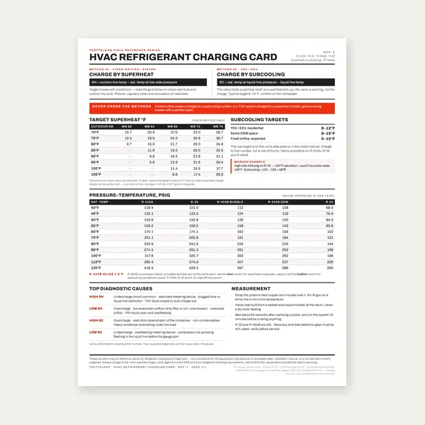
HVAC Refrigerant Charging Card
$3.99
Buy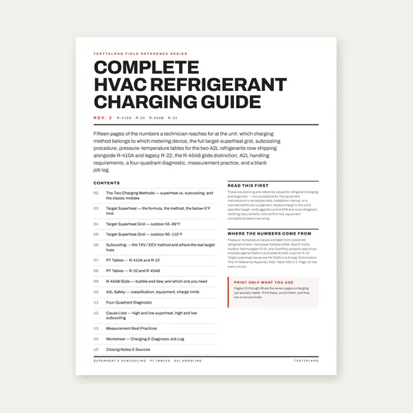
Complete HVAC Charging Guide
$12.99
Buy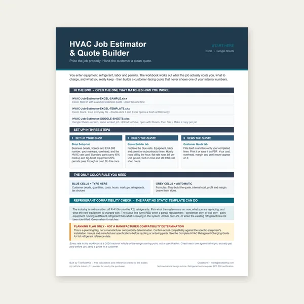
HVAC Job Estimator
$29.00
Buy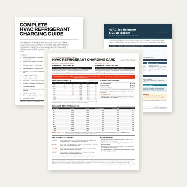
HVAC Complete Bundle
$39.00
BuyCheckout opens here — you stay on this page.
The instruments that decide whether the number is real
Six measurements go in and everything else is arithmetic. Airflow scales the whole answer; the supply wet bulb sets the latent half of it, and it is a small difference between two nearly equal numbers. No amount of care with the equations rescues a bad reading, which is why the instruments matter more here than the maths does.
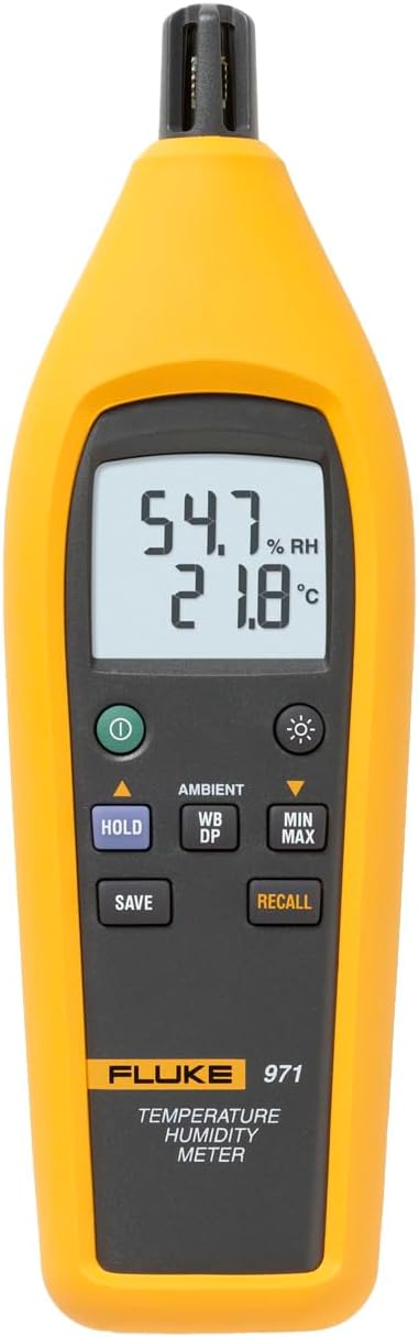
Fluke 971 Temperature Humidity Meter
- Dry bulb and relative humidity, with wet bulb and dew point computed
- Covers both humidity input modes with one instrument
- No wick to dry out, which removes the commonest wet-bulb fault
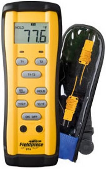
Fieldpiece ST4 Dual Temperature Meter
- Two probes so return and supply are read at the same moment
- Removes the drift you get walking one probe between two places
- Displays the difference directly
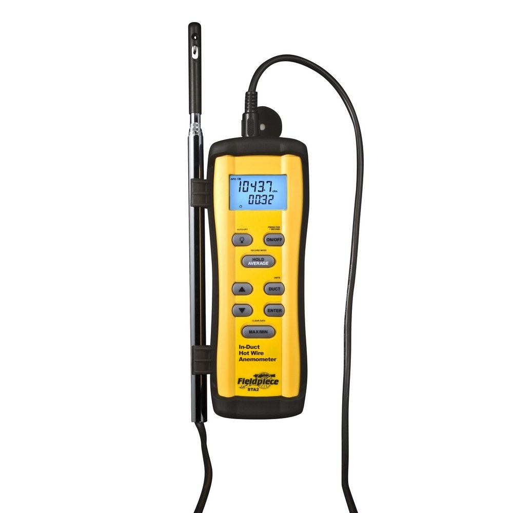
Fieldpiece STA2 In‑Duct Hot Wire Anemometer
- Telescoping hot wire for a proper in-duct traverse
- Airflow multiplies every BTU figure, in the same direction
- A measured traverse beats a nameplate CFM by a wide margin
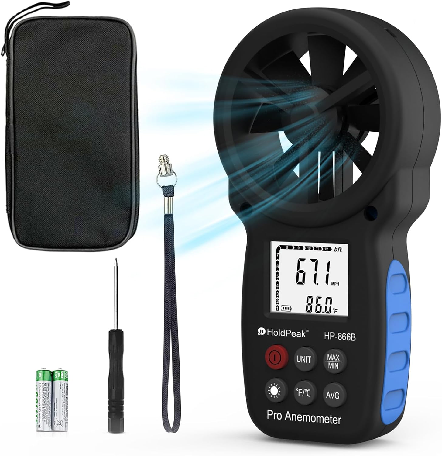
HoldPeak 866B Digital Thermo‑Anemometer
- Vane anemometer for register and grille face velocities
- Reads air temperature too, so one tool covers two inputs
- A useful cross-check when a duct traverse will not fit
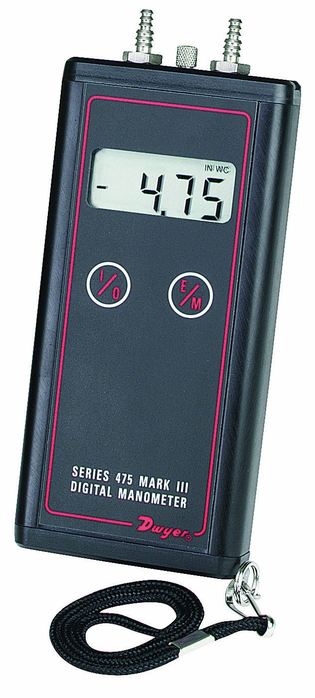
Dwyer Series 475 Mark III Digital Manometer
- Total external static pressure to 0.01 in w.c.
- Gets CFM off the manufacturer’s blower table
- High static is itself a common reason capacity comes up short
As an Amazon Associate, TestTalkHQ earns from qualifying purchases. Prices and availability can change.
Step 3 — what the arithmetic does with them
You do not have to do this by hand, but it is worth knowing what is happening, because it tells you which readings are load-bearing.
First, pressure. Your elevation sets the barometric pressure through the standard-atmosphere equation, and pressure sets density. This is the step most field calculations skip entirely by assuming sea level.
Second, humidity ratio. Each dry-bulb / wet-bulb pair becomes a humidity ratio — pounds of water per pound of dry air. This is the moisture measure that stays put when you heat or cool air, which is why everything downstream is built on it rather than on relative humidity.
Third, enthalpy. Temperature and humidity ratio together give the total energy content of a pound of dry air and the water riding along with it:
Fourth, mass flow. Your CFM divided by the specific volume of the air where you measured it, times sixty, gives pounds of dry air per hour. Note where you measured it: return air and supply air have different specific volumes, typically about 4% apart, and using the wrong one biases everything by that much.
Fifth, the capacity. Mass flow times the enthalpy drop, less a small credit for the enthalpy that leaves in the condensate. Then that total is split into the part that lowered temperature and the part that removed water, and the sensible heat ratio is the first divided by the sum.
Step 4 — reading the answer
You get back four numbers that matter, and they are not equally trustworthy.
Total capacity
The headline. Compare it to the nameplate only as a sanity check, because a nameplate is a rating taken at one specific condition. ANSI/AHRI Standard 210/240’s cooling test table specifies 80.0 °F dry bulb and 67.0 °F wet bulb entering the indoor unit with 95.0 °F dry bulb entering the outdoor unit for the A test. If your return air is cooler or drier than that — and on most service calls it is — the coil has less to work with and less capacity is the correct outcome, not a fault.
Sensible heat ratio
The most robust number on the page, and the one people ignore. Because SHR is the ratio of two figures that both scale with airflow, an airflow error cancels out of it completely. If you took a 10% optimistic CFM, every BTU figure is 10% optimistic and the SHR is exactly right. That makes it the number to trust when you are least sure of your traverse.
Latent capacity and moisture removal
Weakest, because it rests on a small difference between two nearly equal wet-bulb readings. Treat it as an order of magnitude unless your instruments are good and your technique was careful.
Airflow per ton, as an output
The calculator divides your measured CFM by the tons it measured. That is a genuinely informative number because neither half was assumed. A system running well above 400 CFM per ton is moving too much air across the coil for good dehumidification — you will see it in a high SHR as well. Well below, and the coil runs colder, condenses more, and is heading toward icing.
What changes the sensible heat ratio, and which lever you hold
Two things set SHR, and only one of them is yours.
How wet the entering air is. More moisture in the return air means more condensation on a given coil surface, a bigger latent share and a lower SHR. This is the weather and the building, and it is not adjustable on a service call.
How fast the air crosses the coil. This one is yours. More airflow means less contact time and a warmer coil surface, so less water condenses and SHR rises. Less airflow means a colder surface, more condensation and a lower SHR — until it is low enough to freeze the coil, which is the limit on that adjustment.
That is why blower speed is a dehumidification control and not merely an airflow control, and it is the practical reason to measure SHR at all: it is the feedback signal that tells you whether a speed-tap change did what you intended.
A worked example, start to finish
A three-ton split system, nameplate 36,000 BTU/h, in a house at 1,000 feet. A duct traverse gives 1,200 CFM. The return plenum reads 78 °F dry bulb and 64 °F wet bulb; the supply plenum, downstream of the blower, reads 57 °F dry bulb and 55.5 °F wet bulb.
| Quantity | Return air | Supply air |
|---|---|---|
| Dry bulb / wet bulb | 78.0 / 64.0 °F | 57.0 / 55.5 °F |
| Humidity ratio | 70.0 gr/lb | 65.6 gr/lb |
| Enthalpy | 29.67 BTU/lb | 23.86 BTU/lb |
| Specific volume | 14.28 ft³/lb | 13.71 ft³/lb |
| Result | Value |
|---|---|
| Barometric pressure at 1,000 ft | 14.173 psia |
| Dry air mass flow | 5,042 lb/h |
| Total capacity | 29,213 BTU/h (2.43 tons) |
| Sensible capacity | 25,880 BTU/h |
| Latent capacity | 3,333 BTU/h |
| Sensible heat ratio | 0.886 |
| Moisture removal | 3.14 lb/h — about 3 pints an hour |
| Airflow per ton delivered | 493 CFM/ton |
| Against the nameplate | 81% |
Computed from ASHRAE Handbook—Fundamentals chapter 1 and reproduced independently in build verification (CHECK 11) before publication.
What does that tell you? Three things, and one non-thing.
- 81% of nameplate is not automatically a fault. The return air is 78 °F rather than AHRI’s 80, and drier than AHRI’s 67 °F wet bulb. Less to work with, less capacity.
- 493 CFM per ton is on the high side. Nearly a hundred over the usual 400 design target, which fits with the high SHR — the air is crossing the coil quickly and not giving up much water.
- SHR 0.886 says this machine is doing very little dehumidification. If the homeowner’s complaint is “it’s cold but clammy,” you have just found the mechanism, and the blower speed tap is where to look.
- What it does not tell you is why. High airflow is one explanation. So is a low charge, a dirty coil, or a metering device not doing its job. This measurement narrows the field and orders the next checks; it does not close the case.
The shortcut constants, and when to stop using them
Everybody learns 1.08 and 4.5 before they learn a psychrometric equation, and there is nothing wrong with them as long as you know what they assume. CED Engineering’s psychrometrics course derives the whole family in three lines:
sensible = 4.5 × 0.24 = 1.08
latent = 4.5 × 1054 ÷ 7000 = 0.68 per grain
All three rest on 0.075 pounds per cubic foot — which is 13.333 cubic feet per pound, the specific volume of dry air at sea level near 70 °F. Three assumptions. On a load estimate, where the inputs are assumptions anyway, they cost you nothing. On a measurement, they are a systematic bias in a known direction: they always overstate, because real air is always less dense than that.
| Where you are | How far the 4.5 constant overstates mass flow |
|---|---|
| Sea level, AHRI 80/67 return air | 3.7% |
| 2,500 ft, 78/65 return air | 11.8% |
| 5,280 ft (Denver), 80/67 return air | 21.1% |
Specific volumes from ASHRAE eq (26) at the barometric pressure eq (3) gives for each elevation.
The bottom row is the one that should change behaviour. In Denver, standard-air constants report a fifth more capacity than the equipment is delivering. That is the difference between “within tolerance” and “call the manufacturer.”
Frequently asked questions
How do you measure delivered cooling capacity in the field?
Measure the airflow across the coil in CFM, then the dry-bulb and wet-bulb temperatures entering and leaving it. Convert each pair to an enthalpy using the ASHRAE psychrometric equations at your local barometric pressure, work out the dry-air mass flow from the airflow and the specific volume of the air where you measured it, and multiply the mass flow by the enthalpy drop. That is the total capacity; splitting it by temperature and by moisture gives the sensible and latent parts.
Where exactly should the temperature probes go?
The return reading belongs in the return plenum close to the coil, not at the thermostat, so it includes any heat the return duct picks up. The supply reading belongs downstream of the coil and out of line of sight of it, because a cold coil radiates and makes an exposed probe read low. Note whether the blower is upstream or downstream of your supply probe, because that determines whether fan heat is in the measurement.
How accurate does the airflow measurement need to be?
Very, if you care about the BTU figures, because airflow multiplies all of them linearly. A 10% error in CFM makes total, sensible and latent all 10% wrong in the same direction. It does not affect the sensible heat ratio at all, though, because that is a ratio of two numbers that both scale with airflow.
Why does a dry or dirty wick matter so much?
A dry wick reads toward the dry-bulb temperature, which makes the air look drier than it is. On the supply side that understates the moisture removed, understates latent capacity, and pushes the sensible heat ratio up. Since supply air off a wet coil is within a couple of degrees of saturation anyway, a small wet-bulb error there is a large proportional error in the latent result.
Should I use a sling psychrometer or a digital hygrometer?
Either, as long as you use the same one for both readings so any bias partly cancels. A sling has no electronics to drift but does have a wick that can dry out or foul. A digital instrument removes the wick but is least accurate above 90% relative humidity, which is exactly where supply air sits. The calculator accepts wet bulb or relative humidity and runs both through the same equations.
Does the condensate drain really check the calculation?
Yes, and it is free. The latent result comes out as pints per hour of water. Catch the drain for ten minutes and multiply by six. Rough agreement means your humidity readings are sound; a dry drain against a large calculated latent figure means either the readings are wrong or the condensate is going somewhere it should not be.
Do I need to correct for elevation?
Yes, above a few hundred feet it stops being negligible. Capacity depends on the mass of air moved, and lower barometric pressure means less mass per cubic foot. At 2,500 feet the same CFM carries about 12% less air by weight than at sea level, and at 5,280 feet about 21% less.
What airflow per ton should the system be running?
The common design target is around 400 CFM per ton, higher for sensible-heavy dry climates and lower where dehumidification matters more. Treat it as a design target, not a measurement input: the calculator reports CFM per ton as an output computed from the capacity it measured, so the comparison is meaningful rather than circular.