Where each input genuinely comes from, how to read the rating points on an AHRI certificate, the load line and capacity equations from the federal test procedure, a worked example end to end, and the two thermostat settings the answer exists to inform.
Four numbers, and where each one really comes from
A balance point calculation takes four inputs and gives one answer. The arithmetic is trivial — two straight lines and the point where they cross. Everything that makes the answer right or wrong happens before the arithmetic, in where you got the four numbers.
Two of them describe the house: the design heat loss and the outdoor temperature it was calculated at. Two describe the machine: its heating capacity at 47 °F and at 17 °F. Get all four from their proper sources and the answer is solid. Substitute a plausible-looking number for any one of them and the answer moves by several degrees, which moves the backup heat by kilowatts.
The design heat loss
This is the whole-house heating load from a Manual J calculation, at your winter outdoor design temperature. There is no honest substitute. A furnace’s input rating tells you what a previous contractor guessed. Output rating tells you the same thing multiplied by an efficiency. Square-footage rules produce numbers that can be off by half in either direction depending on the vintage, the envelope and the windows — we have laid that case out in detail in rule of thumb versus Manual J heat loss and there is no point repeating it here.
What matters for this page is the leverage. In the worked example below, a 25% error in the load figure moves the balance point by roughly eight degrees and the backup heat requirement by more than two kilowatts. There is no way to be right about a balance point while being wrong about the load.
The winter outdoor design temperature
The 99% or 99.6% winter design dry bulb for the location, and critically, the same one the Manual J was run at. Pairing a load calculated at 10 °F with a design temperature of 0 °F does not make the calculation conservative; it makes the load line the wrong slope, which pushes the balance point in a direction that depends on which way the mismatch went.
For orientation, the federal test procedure divides the country into six climate regions with outdoor design temperatures of 37, 27, 17, 5, −10 and 30 °F. Those are not a substitute for your local design condition, but they bracket it.
The two AHRI heating capacities
These come off the AHRI certificate for the exact outdoor unit and indoor coil combination being installed — not the outdoor unit alone, and not the nominal tonnage multiplied by 12,000. A 3-ton heat pump does not produce 36,000 Btu/h of heat at 47 °F, and what it produces at 17 °F is a different number again.
If the certificate gives you the 35 °F and 5 °F figures as well, use them. The 35 °F figure pulls the middle of the capacity curve down where frost and defrost live. The 5 °F figure replaces an extrapolation with measurement at exactly the temperatures where the extrapolation is least trustworthy.
The two lines
Picture outdoor temperature along the bottom of a graph and Btu per hour up the side.
The building load line slopes down to the right. At the winter design temperature it equals your Manual J number. As it gets milder the house wants less heat, and at some temperature — the zero-load temperature — internal gains and sunlight cover the losses entirely and the load reaches zero.
The capacity line slopes up to the right. At 17 °F the machine makes its H3 rating; at 47 °F it makes its H1 rating; in between it runs roughly straight.
Qh(T) = Qh(17) + [Qh(47) − Qh(17)] × (T − 17) ÷ 30
Balance point: the T where Qh(T) = BL(T)
Backup heat, kW = [ BL(Tdesign) − Qh(Tdesign) ] ÷ 3,412
Neither line is folklore. The straight load line with a zero-load intercept is the form the federal test procedure uses in Equation 4.2-2 of 10 CFR 430 subpart B appendix M1, which names Tzl the zero-load temperature. The capacity interpolation is Equation 4.2.1-4 from the same appendix, which is written in terms of exactly the H1, H2, H3 and H4 rating points above. And the balance point itself is defined in section 4.2 in words: resistive elements run “when operating below the balance point”, a condition that “occurs when the building load exceeds the space heating capacity of the heat pump condenser”.
The zero-load temperature is a choice you are making
65 °F is the traditional answer and the base heating degree days have always been counted from. The current federal procedure does not use it: Table 20 of appendix M1 assigns a zero-load temperature by climate region, running from 55 to 58 °F.
Region IV 55 °F Region V 55 °F Region VI 57 °F
In practice the difference is a couple of degrees, and the calculator reports the answer both ways so you can see it rather than take it on trust. The honest reading is that a house does not stop needing heat at one crisp temperature at all. Sun on the south elevation, an oven, four people in a room and a windless afternoon move the real no-load point around by several degrees within a single day. A balance point is the middle of a band, not a threshold.
HVAC
HVAC Refrigerant Charging Card
$3.99
Buy
Complete HVAC Charging Guide
$12.99
Buy
HVAC Job Estimator
$29.00
Buy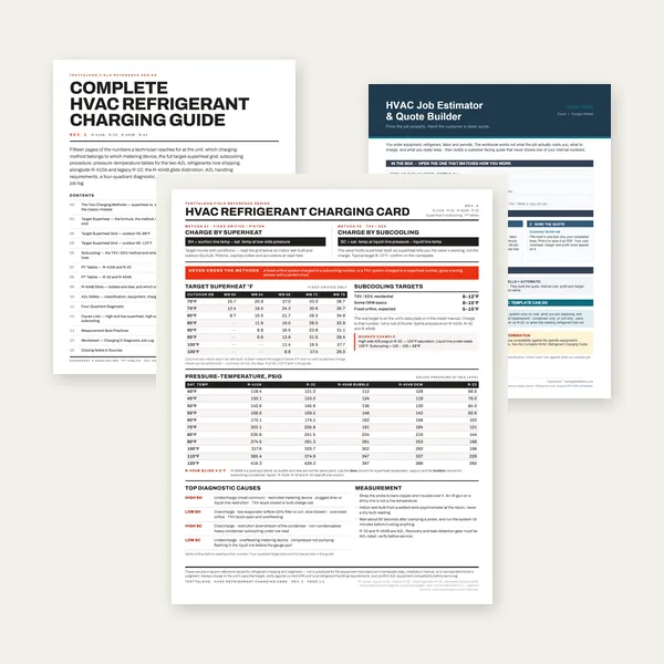
HVAC Complete Bundle
$39.00
BuyCheckout opens here — you stay on this page.
Where the answer actually gets applied
A balance point that lives only in a spreadsheet changes nothing. Two settings in the thermostat decide how much of the winter runs on the compressor and how much runs on resistance heat, and a clamp on the heater kit is the only way to find out which of them is winning. These are the parts of the job that turn the calculation into a lower bill.

ecobee Smart Thermostat Premium
- Runtime history separates compressor hours from aux hours
- Remote sensors show whether the house really drifts at design
- Heat pump settings include compressor and aux temperature limits
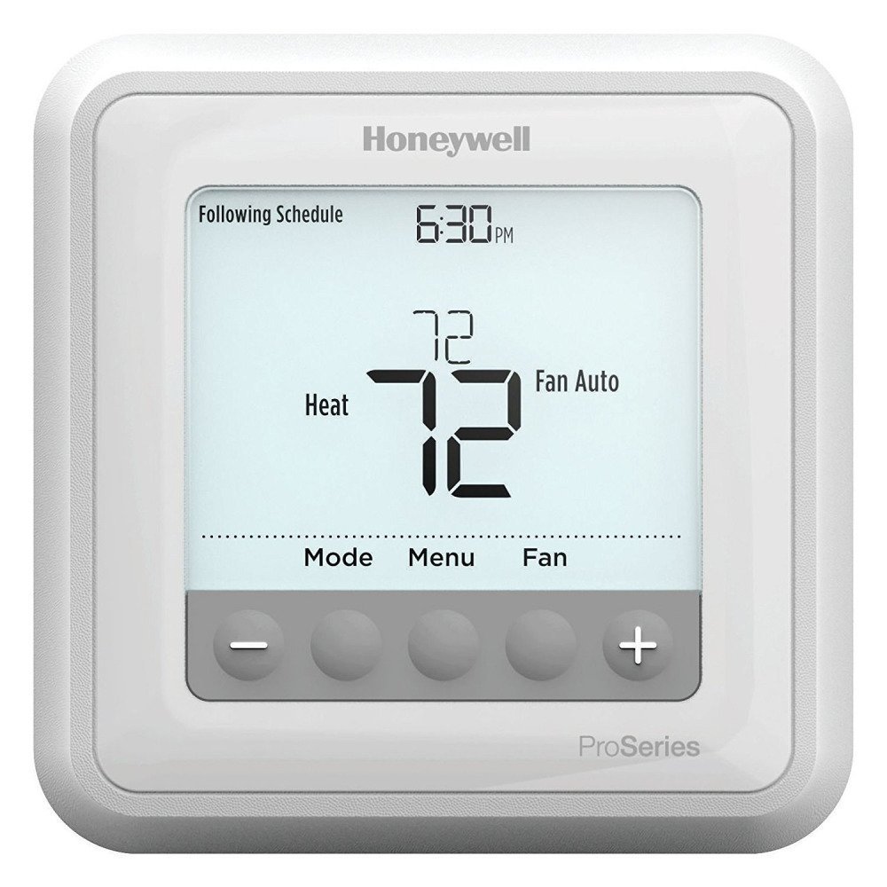
Honeywell T6 Pro Thermostat
- Installer setup exposes the heat pump staging parameters
- A stable setpoint is what makes a balance point observable
- The common replacement when a factory default was never changed

Sensi Touch 2 Smart Thermostat
- Usage reporting makes an always-on aux stage obvious
- C-wire required, which most heat pump air handlers already have
- Cheap way to catch a winter of unnecessary resistance heat
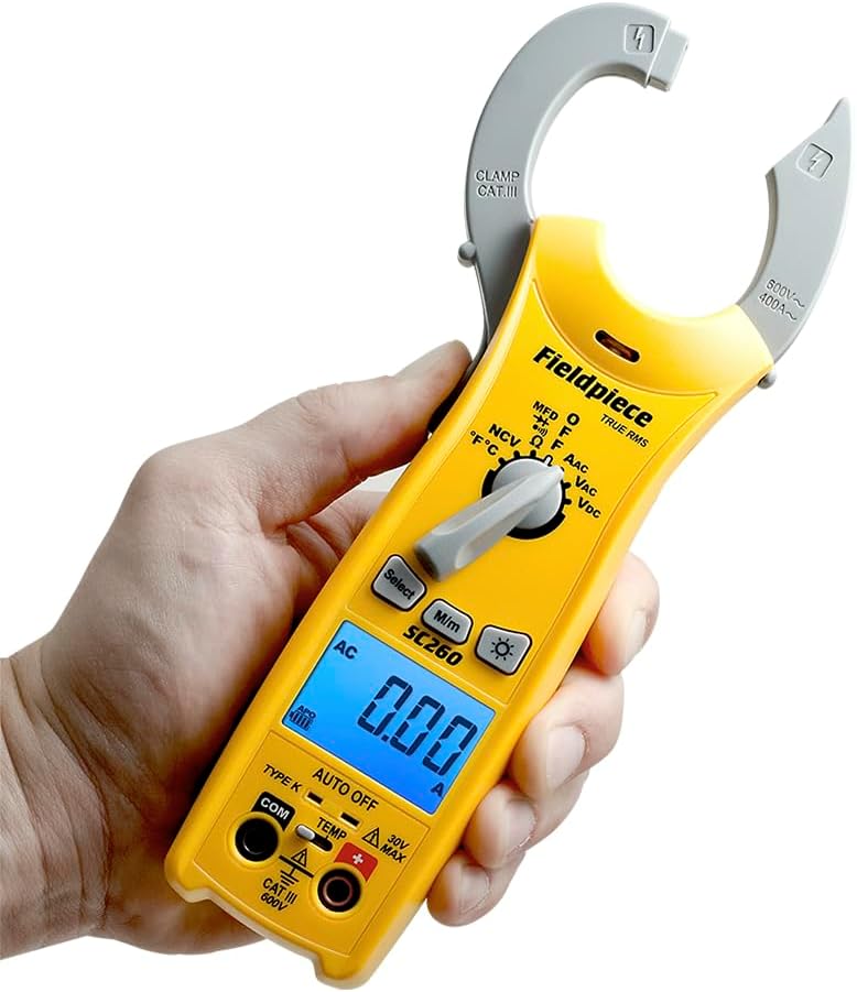
Fieldpiece SC260 Clamp Multimeter
- Clamp the heater kit legs and see which stages energise
- True RMS, compact enough for an air handler cabinet
- Turns “the strips come on a lot” into an amp reading

Klein Tools CL800 Digital Clamp Meter
- 1000V rating covers commercial air handler backup heat
- Amps times volts is how kW of strip heat gets confirmed
- True RMS matters on anything fed from a drive or inverter
As an Amazon Associate, TestTalkHQ earns from qualifying purchases. Prices and availability can change.
A worked example, start to finish
Load line. 36,000 ÷ (65 − 5) = 600 Btu/h per degree. At 25 °F the house wants 600 × (65 − 25) = 24,000 Btu/h.
Capacity line. (34,000 − 21,000) ÷ 30 = 433 Btu/h per degree. At 25 °F the machine makes 21,000 + 433.3 × 8 = 24,467 Btu/h.
They cross at 24.5 °F. That is the balance point.
At the design condition. At 5 °F the compressor makes 21,000 − 433.3 × 12 = 15,800 Btu/h against a 36,000 Btu/h load. The shortfall is 20,200 Btu/h, which at 3,412 Btu/h per kW is 5.92 kW of backup heat. The compressor still carries 43.9% of the coldest day on its own.
What that 5.92 kW is and is not
It is the thermal requirement at the design condition. It is not automatically the heater kit you fit. Four things push the real selection around, and all of them are outside this calculation:
- Kits come in the sizes they come in. You will be choosing from the ratings the manufacturer publishes for that air handler, not from a continuous scale.
- The air handler has a minimum airflow for each kit. A larger kit than the blower can handle is not an option regardless of what the arithmetic wants.
- Recovery from setback and defrost. Both call for backup heat at temperatures well above the balance point, and neither is a design-day condition.
- The electrical side. Backup heat is a continuous load with real consequences for the branch circuit, the panel and sometimes the service, and it is sized and installed to the NEC and the manufacturer’s instructions, not to a web page.
What the number does do is stop the habit of fitting 10 or 15 kW because that is what was in the van. The gap between 5.92 kW calculated and 15 kW fitted is not free — it is paid for in conductor, breaker and occasionally service capacity, and a control that stages badly will happily energise all of it.
The two settings the answer is for
Having a balance point matters because two thermostat parameters should be set from it, and in the field they very often are not.
Auxiliary heat lockout — sometimes “aux maximum outdoor temperature” — prevents the resistance heat energising above a set outdoor temperature. Set a few degrees above the calculated balance point it does exactly what you want: the compressor gets room to recover from a setback on a mild morning without the strips joining in, and the strips are still available on the nights they are genuinely needed.
Compressor lockout — “compressor minimum outdoor temperature” — does the opposite and is the more expensive of the two to get wrong. It switches the compressor off below a set temperature and hands the whole load to resistance heat. In the worked example, a 30 °F compressor lockout would shut down a machine that was still producing over 26,000 Btu/h and put the entire 21,000 Btu/h load onto the strips, at roughly three times the running cost.
There is a third number that gets confused with these constantly, and it is genuinely different: the dual-fuel economic switchover temperature. That one is arithmetic on utility rates rather than on capacity, and it is covered separately in balance point versus switchover temperature.
What moves a real balance point away from the calculated one
The calculation uses published ratings at standard test conditions. A house is not a test chamber. The gap between the two shows up in predictable places:
- Airflow. Rated capacity assumes rated airflow. A restricted filter, a crushed flex run or a blower set to the wrong tap takes real capacity below the certificate, which raises the balance point. Check it with total external static pressure before blaming the machine, and confirm the air side is delivering with a delta-T check.
- Refrigerant charge. An undercharged system loses heating capacity where it hurts most, at low outdoor temperatures. Verify with superheat and subcooling rather than by weight of guesswork.
- Line set length and lift. Long runs and significant vertical separation carry capacity penalties the manufacturer publishes and the AHRI rating does not include.
- Defrost. Time spent in defrost is time not heating the house, plus it pulls heat back out of the indoor air. Frequent defrost cycles near freezing are exactly where the 35 °F rating comes from and exactly why a straight 47-to-17 line overestimates output there.
- Wind and infiltration. The design load was calculated at a design wind speed. A windy site or a leaky envelope steepens the real load line.
- Variable-capacity equipment. An inverter-driven machine modulates and, in many cases, holds capacity better at low temperature than a straight line between two rating points predicts. Here the straight-line answer is pessimistic rather than optimistic, and the 5 °F rating is worth chasing down.
None of these is a reason to skip the calculation. They are the reason to treat the answer as a well-founded starting point and then verify the installation rather than assume it.