Weld Shrinkage & Distortion Guide
What causes weld metal to pull, how transverse and longitudinal shrinkage differ, and how to compensate in layout
Use this with the free Weld Shrinkage & Distortion Allowance Calculator. For diagnosing warp after the fact, see Distortion Troubleshooting. For sequence recipes, see Weld Sequencing.

What Causes Weld Shrinkage
When you deposit weld metal, a narrow strip of base metal reaches melting or near-melting temperature. That hot metal expands. As the puddle solidifies and cools, the weld and heat-affected zone contract. Because the solidified weld is already fused to colder plate, the contraction does not happen freely — it pulls the surrounding parts toward the weld.
Think of the weld as a short, strong cable that shortens as it cools. The plates have to move or the assembly has to store residual stress. In lightly restrained work, you see movement (distortion). In heavily restrained work, you see stress — and sometimes cracking — instead of obvious warp.
Transverse vs Longitudinal Shrinkage
Transverse shrinkage acts across the joint — plates pull together, gaps close, and overall width shrinks. This is the allowance most layout people care about when cutting blanks or setting root openings.
Longitudinal shrinkage shortens the assembly along the weld length. Long seams on frames, beams, and tanks can pull hole patterns out of position even when the transverse gap looks fine.
| Direction | What you see | Typical planning response |
|---|---|---|
| Transverse | Gap closes; width undersize | Add layout allowance / root opening budget |
| Longitudinal | Length foreshortens; bowing | Leave extra length; balance seams; check hole datums |
| Angular | Joint rotates out of plane | Preset, clamp, alternate sides (see troubleshooting) |
How to Estimate and Compensate in Layout
Shop estimates start from thickness, joint type, material, and pass count — exactly the inputs in the shrinkage calculator. Mild steel is the baseline. Stainless typically moves more for the same joint because of higher thermal expansion. Aluminum moves still more and conducts heat farther, so thin aluminum can buckle even when the calculated transverse number looks small.
- Identify which print dimension closes on the weld.
- Estimate transverse allowance for that joint (calculator or coupon).
- Add the allowance to blanks or root opening — not to every unrelated dimension.
- For long seams, budget longitudinal foreshortening on overall length and critical hole centers.
- After the first article, measure actual shrink and update the shop standard.
Why Multi-Pass Welds Compound Shrinkage
Each pass reheats metal near the joint and adds another contraction cycle. Pass two does not simply double pass one — the first pass already ties the plates together, so later passes work against a stiffer joint. Shrinkage still rises with pass count, but with diminishing returns. That is why thick-plate multi-pass grooves need both allowance planning and sequence control.
Heat stacking makes it worse: if you weld pass after pass without letting the joint cool, the thermal field widens and more base metal participates in shrinkage. Interpass temperature control (see the Interpass Temperature Calculator) is therefore a distortion control tool, not only a metallurgy tool.
Real-World Fabrication Implications
Parts end up out of tolerance when drawings assume “cut to size, weld, done.” Common failure modes:
- Door frames and boxes that will not square because continuous fillet corners pulled in.
- Beam flanges that camber after one-sided flange-to-web welds.
- Tank shells that go out-of-round after longitudinal seams without balanced sequencing.
- Hole patterns that miss mating parts because longitudinal shrink was ignored.
Joint selection also matters. Double-sided grooves and balanced fillets reduce angular pull compared with single-sided heavy welds — covered in the Weld Joint Design Guide distortion section. Heat input bands that drive how much metal you heat are covered in the Heat Input Guide. This guide stays focused on shrinkage mechanics and layout compensation.
Recommended Welding Gear
Gear that supports clean fit-up and controlled heat while you fight distortion
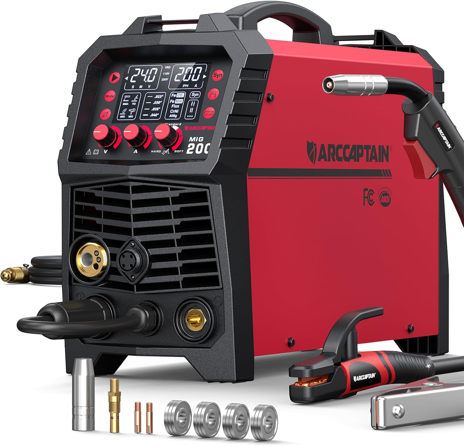
ARCCAPTAIN 6-in-1 Multi-Process
- Stable settings for sequenced fab
- MIG / TIG / stick flexibility
- Dual voltage
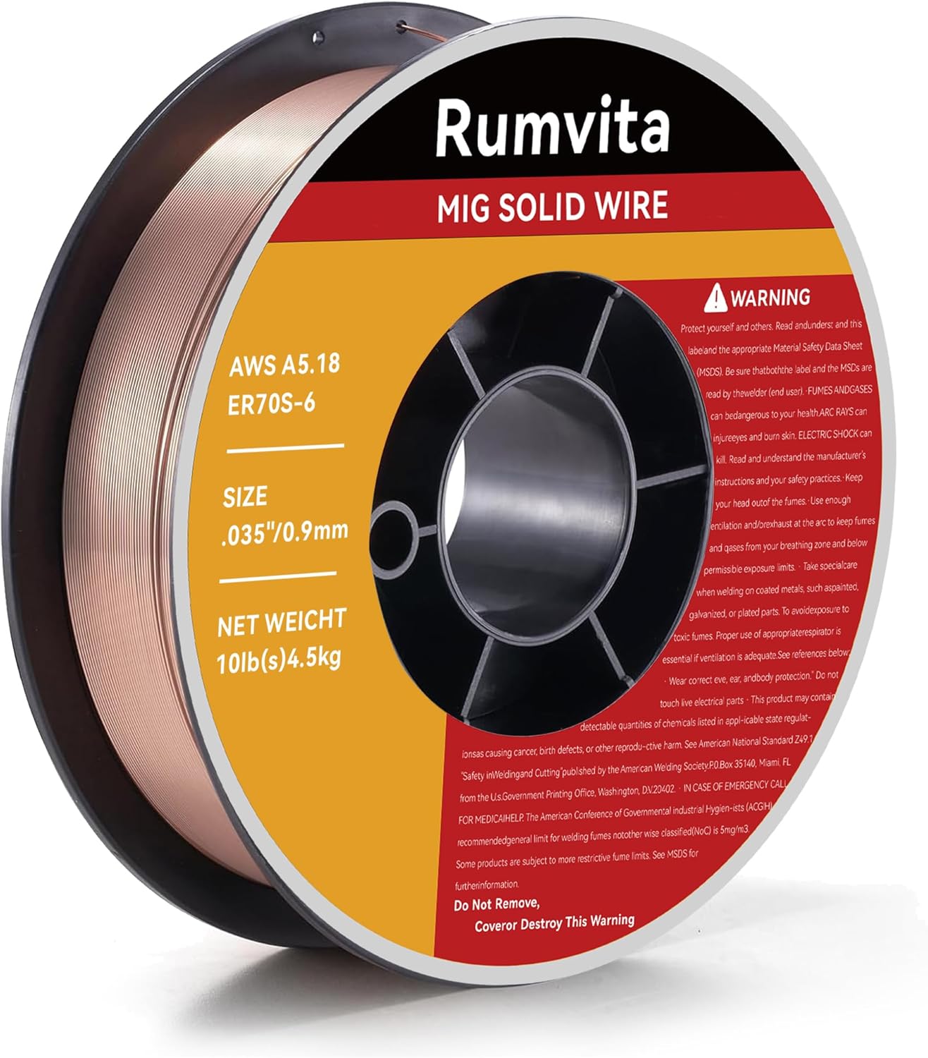
ER70S-6 MIG Wire (.035")
- Consistent feed for stable amps
- Common fab diameters
- Low-spatter copper coating
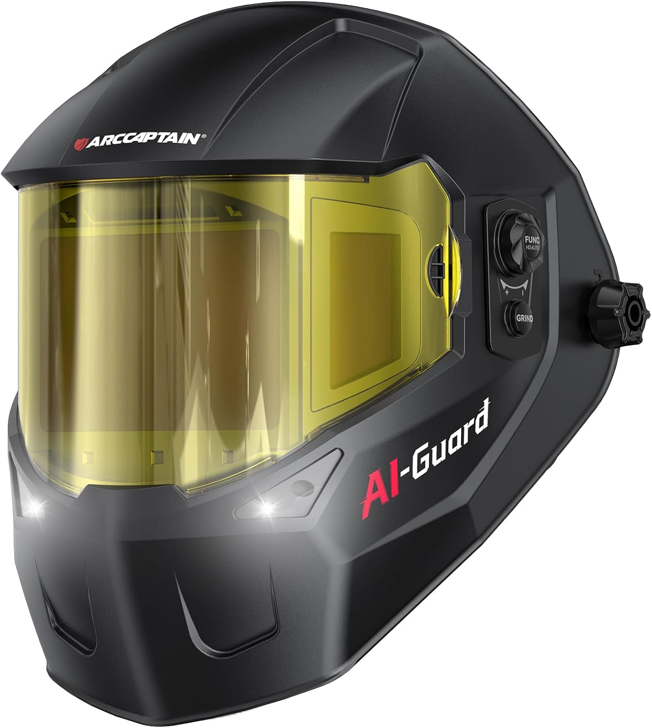
ARCCAPTAIN Halo Helmet
- Wide true-color view
- Spot heat tint and warp early
- Comfortable for long sequences
As an Amazon Associate, TestTalkHQ earns from qualifying purchases.
Material Coefficients in Plain Language
Mild steel is the reference. Stainless often needs roughly 40–50% more transverse allowance for similar joints. Aluminum can approach roughly double mild-steel movement and is far more buckling-prone on sheet. Always confirm on your alloy and temper.
Restraint Changes Everything
A free plate on sawhorses shrinks differently than a frame locked in a fixture. Heavy restraint reduces visible movement but stores residual stress. If you fixture hard, reduce allowance and watch for cracking on hardenable steels.
When to Trust a Coupon Over a Formula
Any online estimate — including ours — assumes average technique and light-to-moderate restraint. Aerospace fit-ups, code-critical bridges, and precision machine bases deserve coupon data under the real WPS.
Next Steps
Run your joint in the calculator, then plan the weld order with sequencing technique. If the part already warped, jump to troubleshooting.