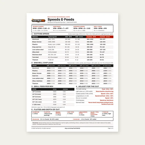
Machining Speeds & Feeds Card
One page. Speeds, chip load and drill feed, imperial and metric.
$3.99
BuyFeed per tooth, IPT, and feed rate — how chip load differs from SFM and how to get it right
Chip load is the thickness each flute removes per revolution. It sets table feed rate once RPM is known. Too low causes rubbing and heat; too high causes chatter and broken tools. This guide explains how to read chip-load charts, diagnose bad feeds, and avoid common CNC mistakes.
Use the Chip Load Calculator for instant IPM or IPT from RPM and flute count, or start with the Milling Speed and Feed Calculator for full SFM-to-RPM recommendations.

Chip load — also called feed per tooth (FPT) or inches per tooth (IPT) — is the thickness of material each cutting flute removes in one revolution. It answers a different question than surface feet per minute (SFM). SFM describes how fast the cutting edge travels relative to the workpiece; that value converts to spindle RPM based on cutter diameter. Chip load describes how aggressively each tooth bites into the material at that RPM; that value converts to table feed rate based on flute count.
You can have the correct RPM for your material and still destroy a tool if feed rate is wrong. A 4-flute end mill at 3,000 RPM with 0.004 in/tooth chip load needs 48 IPM. The same RPM at 10 IPM produces only 0.00083 in/tooth — the tool rubs, heats up, and dulls within minutes. Conversely, 120 IPM at the same setup yields 0.01 in/tooth — likely chatter and a broken corner on carbide. Use the Chip Load Calculator to solve either direction instantly.
Feed Rate (IPM) = Chip Load (in/tooth) × Number of Flutes × RPM
Rearranged to find chip load from a known feed: Chip Load = Feed Rate ÷ (Flutes × RPM)
4-flute end mill, 3,000 RPM, target 0.004 in/tooth in aluminum.
Feed Rate = 0.004 × 4 × 3,000 = 48.0 IPM
Programmed 30 IPM, 4 flutes, 2,500 RPM in mild steel.
Chip Load = 30 ÷ (4 × 2,500) = 0.003 in/tooth
The Milling Speed and Feed Calculator recommends SFM, RPM, chip load, and feed together from material and cutter inputs. This guide and the chip load calculator focus on the feed-per-tooth side when you already know your RPM.
Manufacturer charts and shop reference tables list chip load ranges by tool diameter and material. Carbide in aluminum might show 0.004–0.008 in/tooth for a 1/2-inch end mill; the same diameter in stainless might show 0.001–0.002 in/tooth. Read the range as a starting window, not a single number. Start near the low end on an unfamiliar setup, then increase feed until chips and sound confirm you are cutting — not rubbing.
Diameter columns matter because chip load scales with tool size. A 1/8-inch end mill might top out at 0.001 in/tooth in steel while a 1-inch cutter can handle 0.005–0.010 in/tooth. Material columns reflect how aggressively each alloy can be cut: aluminum and brass allow higher IPT; stainless and hardened steel demand lower IPT to avoid work hardening and heat buildup.
Flute count changes feed rate at the same chip load — more flutes mean higher IPM for identical IPT. A 2-flute aluminum cutter at 0.006 in/tooth and 4,000 RPM needs 48 IPM; a 4-flute at the same chip load and RPM needs 96 IPM. Always include flute count in the math.
Rubbing is the core failure mode. The cutting edge slides instead of shearing, generating friction heat without efficient chip formation. Audible signs include squealing, especially in steel and stainless. Visual signs include powder or dust instead of chips, discolored workpiece surface, and rapid edge rounding. In stainless and titanium, rubbing work-hardens the surface immediately, making the next pass even harder.
Operators and programmers often cause low chip load by reducing feed to improve surface finish or out of caution on a new part. Finish passes do use lower IPT — but roughing passes below minimum chip load wear tools faster than aggressive cuts. If chips are wispy and the tool sounds wrong, increase feed before you reduce RPM.
Excessive chip load overloads the flute cross-section and deflects the tool. Chatter — rhythmic vibration in the cut — is the most common sign. Surface finish becomes rough with visible tool marks. Carbide corners chip or the entire tool snaps, especially in full-width slotting. Chips may be thick, blue, or purple in steel, indicating extreme heat from mechanical overload rather than rubbing.
High chip load failures are often immediate and dramatic. They are more common when someone copies feed values from a rigid CNC production setup onto a manual mill with backlash, or when radial engagement is 100% of cutter diameter without reducing IPT.
Published chip loads assume a stiff spindle, tight workholding, short tool stick-out, and moderate radial engagement. Violate any of those and the achievable chip load drops — sometimes by half or more. Long end mills sticking out of the collet act like springs; heavy chip loads deflect them, changing the effective IPT and causing chatter.
Manual mills with worn leadscrews and backlash cannot climb mill safely at high feed. Even conventional milling on a loose Bridgeport may need 30–40% lower IPT than a Haas VF-2. Fix workholding and minimize stick-out before you chase higher feed rates. A shorter, stubbier tool at lower stick-out often allows higher chip load than a longer tool at chart values.
Flute cross-section area shrinks with diameter. The same IPT on a 1/4-inch end mill and a 1-inch end mill imposes vastly different stress per unit of tool strength. Small tools also have less core diameter and are more brittle in carbide grades. That is why reference tables step down IPT as diameter decreases — a 1/8-inch carbide end mill might run 0.0005–0.001 in/tooth in steel while a 3/4-inch tool runs 0.004–0.007 in/tooth.
Small tools also run at higher RPM for the same SFM, which multiplies feed rate for a given IPT. Always verify the machine can execute the calculated IPM and that the control resolution (minimum feed increment) does not round your feed so low that actual chip load falls below the rubbing threshold.
Using linear feed for rotary motion without flute count: Some CAM posts output surface feed or plunge feed without correctly applying IPT × flutes × RPM on engagement moves. Verify the posted G-code feed against the formula.
Copying feed from a different tool: Feed rate is not portable between cutters. A 6-flute finishing end mill and a 3-flute rougher at the same RPM need different IPM for the same IPT.
Ignoring chip thinning in adaptive toolpaths: High-efficiency toolpaths use low radial engagement; the CAM may calculate higher IPT because the average chip thickness differs from conventional full-slot formulas. Trust the CAM for HEM, but verify on first run.
Rounding feed to zero on small tools: On tiny cutters at moderate RPM, the correct IPM can be under 5. If your control rounds to whole numbers, you may end up rubbing. Use decimal feed where the control allows.
Forgetting to scale for material: Feed that works in 6061 aluminum will break a tool in 304 stainless. Always recalculate chip load when material changes, even if tool and RPM stay the same.
Starting range: 0.004–0.008 in/tooth with a 4-flute carbide end mill in a rigid setup. At 3,000 RPM that translates to roughly 48–96 IPM. Increase until chips are large and shiny; reduce if you hear chatter or see built-up edge.
The Milling Speed and Feed Calculator computes SFM, RPM, recommended chip load, feed rate, and MRR from material, cutter type, diameter, and cut dimensions. The Chip Load Calculator is for when you already have RPM and need to set or verify feed from chip load — or audit a program by back-calculating IPT from programmed feed.
Carbide can typically run similar or slightly higher IPT than HSS when RPM is correct, but HSS is more forgiving of low chip load and interrupted cuts. In practice, HSS setups on manual mills often run at the low end of reference ranges because achievable RPM is lower. Do not copy carbide IPT from a high-speed CNC onto HSS in a drill press mill.
One page. Speeds, chip load and drill feed, imperial and metric.
$3.99
Buy
27 pages. Milling, drilling, tapping, turning and CNC routing.
$12.99
Buy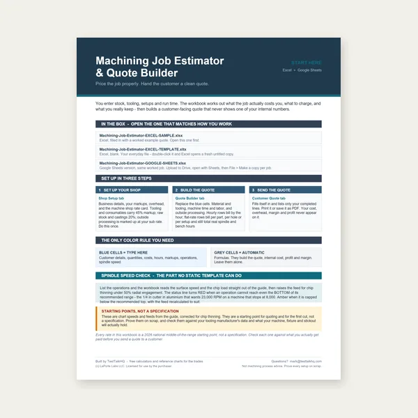
Quote shop work and check operations against your spindle's top speed.
Excel or Google Sheets. Best on a computer.
$29.00
Buy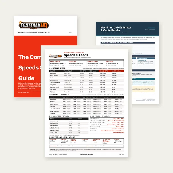
Card, 27-page guide and the estimator workbook. All six files.
Excel or Google Sheets. Best on a computer.
$34.99
$45.98 if bought separately — save $10.99
BuyCheckout opens in a new tab.
Accurate measurement and proper lubrication keep chip-load calculations honest in the shop

Nominal cutter diameter and actual diameter differ enough to shift RPM and chip-load math. Measuring the tool before calculating feed eliminates a common source of rubbing and breakage. The Starrett EC799A reads to 0.0005 inch — the resolution you want when verifying end mill diameter before a precision pass.
Check Price
Correct chip load still produces heat. Lubrication at the cut zone reduces built-up edge in aluminum and helps stainless and steel cuts evacuate chips cleanly. Dry lube is easy to apply on manual mills where flood coolant is not available and pairs well with aggressive aluminum IPT.
Check Price
Collet nuts and toolholder threads see high torque every tool change. Anti-seize prevents galling, keeps runout consistent, and makes accurate chip-load performance repeatable. Inconsistent holder torque shows up as vibration long before you notice it in the numbers.
Check PriceAs an Amazon Associate, TestTalkHQ earns from qualifying purchases.
Every experienced machinist has dulled a tool by feeding too slowly. Chip load is the variable that separates shearing from rubbing. When IPT is below the minimum for your tool and material, the edge skids, work hardens the surface, and heat stays in the tool. When IPT is in range, chips carry heat away and the edge cuts cleanly. Learning to read chips and sound beats memorizing a single feed number for every job.
The calculation order matters. Pick SFM for the material and tool type, convert to RPM with cutter diameter, then pick chip load for the material and diameter, then multiply by flutes and RPM for IPM. Skipping straight to a feed number you used last week ignores whether RPM changed for a different diameter or material. The Cutting Speed & Feed Rate Calculator and Milling Speeds and Feeds Guide cover the SFM and RPM side; this guide owns the IPT and feed side.
Reference chip loads assume peripheral milling with moderate radial engagement. Full-width slotting — 100% radial engagement — doubles the effective tool load at the same IPT. Most shops reduce chip load 25–50% for slotting passes, especially in steel and stainless. Depth of cut matters too: axial DOC beyond half the cutter diameter increases deflection and heat. If you must slot full width, start at the low end of the chart and climb mill on CNC where backlash allows.
Charts, calculators, and CAM posts give starting points. The proof is in the chip. Run a short test pass on scrap or the part's excess stock. Correct steel chips are blue-gray curls; correct aluminum chips are bright and evacuate cleanly; correct stainless chips are short and tight. Adjust feed in 10% steps until sound and chips confirm you are in the cutting window — then lock the value for production.
Chip Load Troubleshooting for symptom diagnosis when IPT looks correct. Climb vs Conventional Milling for direction strategy on CNC vs manual mills.